


INSTALLATION MANUAL
MANUEL D’INSTALLATION INSTALLATIONS-HANDBUCH MANUALE DI INSTALLAZIONE
MANUAL DE INSTALACIÓN
ΕΓΧΕΙΡΙ∆ΙΟ ΕΓΚΑΤΑΣΤΑΣΗΣ
MANUAL DE INSTALAÇÃO
ИНСТРУКЦИЯ ПО УСТАНОВКЕ INSTALLATIONSANVSNING
AIR CONDITIONER
CLIMATISEUR (TYPE SEPARE) KLIMAGERÄT (SPLIT-TYP) CONDIZIONATORE D’ARIA (TIPO SPLIT)
AIRE ACONDICIONADO (TIPO SPLIT)
ΚΛΙΜΑΤΙΣΤΙΚΟ (∆ΙΑΙΡΟΥΜΕΝΟΥ ΤΥΠΟΥ)
AR CONDICIONADO (TIPO SPLIT)
КОНДИЦИОНЕР (РАЗДЕЛИТЕЛЬНЫЙ ТИП)
LUFTKONDITIONERINGSAPPARAT (SPLITTYP)
(SPLIT TYPE)
Not accessible to the general public Vente interdite au grand public Kein öffentlicher Zugang
Non accessibile a clienti generici
No destinado al público en general
Μη προσβάσιµο από το γενικό κοινό
Não acessível ao público em geral
Ограничено для доступа широкой общественности
Inte tillgänglig för allmänheten
4-Way Air Discharge Cassette Type Type cassette à 4 voies de soufflage 4-Wege-Belüftungskassette
Tipo a cassetta con scarico d'aria a 4 vie Modelo de casete de distribución de aire de
4 vías
Εκροή αέρα 4-∆ιευθύνσεων Τύπου Κασέτας
Descarga de ar tipo cassete de 4 vias
4-направленная кассета выписка воздуха
Apparat med 4-vägars luftutsläpp
Indoor Unit/Unité intérieure/Raumeinheit/Unità interna/Unidad interior
Εσωτερική µονάδα/Unidade interior/Внутренний блок/Inomhusenhet
Heat Pump Model |
Cooling Only Model |
Modèle à thermopompe |
Modèle à froid seul |
Geräte mit Heizung |
Geräte nur zur Kühlung |
Modello con pompa di riscaldamento |
Modello solo per raffreddamento |
Modelo con bomba de calor |
Modelo de refrigeración únicamente |
Μοντέλο µε Αντλία Θερµότητας |
Μοντέλο Ψύξης αποκλειστικά |
Modelo de bomba térmica |
Modelo Apenas para Refrigeração |
Модель теплового насоса |
Модель только c охлаждением |
Värmepumpsmodell |
Modell endast för avkylning |
|
|
RAS-M10SMUV-E |
RAS-M10SMUCV-E |
RAS-M13SMUV-E |
RAS-M13SMUCV-E |
RAS-M16SMUV-E |
RAS-M16SMUCV-E |
|
|
Ceiling panel/Panneau pour plafond/Deckenrahmen/Pannello al soffitto/ Panel de techo/Φάτνωµα ρ φής/Painel de tecto/Потолочная панель/ Takpanel
RB-B11MC(W)E
ENGLISH
DEUTSCH FRANÇAIS
ITALIANO
SVENSKA РУССКИЙ ЯЗЫК PORTUGUÊS ΕΛΛΗΝΙΚΑ ESPAÑOL

CONTENTS/SOMMAIRE/INHALT/INDICE
ENGLISH
1 |
SAFETY PRECAUTIONS.......................................................... |
1 |
2 |
ACCESSORY PARTS AND PARTS TO BE PROCURED |
|
|
LOCALLY .................................................................................. |
3 |
3 |
SELECTION OF INSTALLATION PLACE................................. |
4 |
4 |
INSTALLATION OF INDOOR UNIT .......................................... |
6 |
5 |
DRAIN PIPING WORK ............................................................ |
11 |
6 |
REFRIGERANT PIPING AND EVACUATING......................... |
15 |
7 |
EVACUATING ......................................................................... |
17 |
8 |
ELECTRICAL WORK .............................................................. |
18 |
9 |
APPLICABLE CONTROLS...................................................... |
21 |
10 TEST OPERATION ................................................................. |
23 |
|
11 INSTALLATION/SERVICING TOOLS ..................................... |
23 |
|
12 MAINTENANCE ...................................................................... |
24 |
|
Please read this Installation Manual carefully before installing the Air Conditioner.
•This Manual describes the installation method of the indoor unit.
•For installation of the outdoor unit, follow the Installation Manual attached to the outdoor unit.
ADOPTION OF NEW REFRIGERANT
This Air Conditioner is a new type which adopts the new refrigerant HFC (R410A) instead of the conventional refrigerant R22. R410A is an ozone friendly refrigerant.
FRANÇAIS
1 |
MESURES DE SECURITE........................................................ |
1 |
2 |
PIÈCES ACCESSOIRES ET PIÈCES NON FOURNIES .......... |
3 |
3 |
SELECTION DU LIEU D’INSTALLATION ................................. |
4 |
4 |
INSTALLATION DE L’UNITE INTERIEURE.............................. |
6 |
5 |
INSTALLATION DES TUYAUX D’EVACUATION ................... |
11 |
6 |
TUYAUTERIE DE FRIGORIGÈNE ET ÉVACUATION............ |
15 |
7 |
EVACUATION DE L’AIR ......................................................... |
17 |
8 |
INSTALLATION ELECTRIQUE ............................................... |
18 |
9 |
COMMANDES APPLICABLES ............................................... |
21 |
10 ESSAI DE FONCTIONNEMENT ............................................. |
23 |
|
11 |
OUTILS D’INSTALLATION/D’ENTRETIEN............................. |
23 |
12 ENTRETIEN ............................................................................ |
24 |
|
Veuillez lire attentivement ce Manuel d'installation avant d'installer le climatiseur.
•Ce manuel décrit la procédure d'installation de l'unité intérieure.
•Pour installer l'unité extérieure, reportez-vous au Manuel d'installation fourni avec l'unité extérieure.
UTILISATION DU NOUVEAU REFRIGERANT
Ce nouveau type de climatiseur utilise le nouveau réfrigérant HFC (R410A) au lieu du traditionnel R22. Le R410A est un réfrigérant qui respecte la couche d'ozone.
DEUTSCH
1 |
SICHERHEITSVORKEHRUNGEN............................................ |
1 |
2 |
ZUBEHÖR UND BAUSEITS BEREITZUSTELLENDE TEILE... |
3 |
3 |
AUSWAHL DES AUFSTELLUNGSORTES .............................. |
4 |
4 |
INSTALLATION DER RAUMEINHEIT....................................... |
6 |
5 |
INSTALLATION DES KONDENSWASSER-ABLAUFS........... |
11 |
6 |
KÜHLMITTELLEITUNGSSYSTEM UND ENTLÜFTUNG ....... |
15 |
7 |
ENTLÜFTEN DER ROHRLEITUNGEN................................... |
17 |
8 |
ELEKTROINSTALLATION ...................................................... |
18 |
9 |
STEUERUNGSMÖGLICHKEITEN.......................................... |
21 |
10 TESTLAUF .............................................................................. |
23 |
|
11 INSTALLATIONS / WARTUNGSWERKZEUGE ..................... |
23 |
|
12 WARTUNG .............................................................................. |
24 |
|
Bitte lesen Sie dieses Handbuch sorgfältig, bevor Sie mit der Installation des Klimagerätes beginnen.
•In diesem Handbuch wird die Installation der Inneneinheit beschrieben.
•Um die Außeneinheit zu installieren, folgen Sie den Anweisungen des Handbuchs, das der Außeneinheit beiliegt.
EINFÜHRUNG EINES NEUEN KÜHLMITTELS
Dies ist ein neuartiges Klimagerät. Anstatt des herkömmlichen Kältemittels R22 verwendet es das neue HFC Kältemittel R410A. R410A schont die Ozonschicht.
ITALIANO
1 |
PRECAUZIONI PER LA SICUREZZA....................................... |
1 |
2 |
ACCESSORI E PARTI DA ACQUISTARE SUL POSTO .......... |
3 |
3 |
SCELTA DEL POSTO D’INSTALLAZIONE............................... |
4 |
4 |
INSTALLAZIONE DELL’UNITÀ INTERNA ................................ |
6 |
5 |
LAVORO PER TUBAZIONE DI SCARICO.............................. |
11 |
6 |
TUBAZIONI DEL REFRIGERANTE E SCARICO ................... |
15 |
7 |
SPURGO ................................................................................. |
17 |
8 |
ESECUZIONE DEI COLLEGAMENTI ELETTRICI.................. |
18 |
9 |
COMANDI UTILIZZABILI......................................................... |
21 |
10 FUNZIONAMENTO DI PROVA ............................................... |
23 |
|
11 |
ATTREZZI PER L’INSTALLAZIONE/PER LA |
|
|
MANUTENZIONE.................................................................... |
23 |
12 MANUTENZIONE.................................................................... |
24 |
|
Prima di eseguire l'installazione del condizionatore d'aria, leggere attentamente il Manuale d'installazione.
•Questo manaule il metodo d'installazione dell'unità interna.
•Per l'installazione dell'unità esterna, fare riferimento al Manuale d'installazione fornito con l'unità esterna.
ADOZIONE DI UN NUOVO REFRIGERANTE
Questo condizionatore d'aria è di dipo nuovo e impiega il nuovo refrigerante HFC (R410A) invece del R22, tradizionalmente usato. R410A è un refrigerante ecologicamente rispettoso dello strato d'ozono.
i

ÍNDICE/ΠΕΡΙΕΧΟΜΕΝΑ/ÍNDICE/СОДЕРЖАНИЕ
ESPAÑOL
1 |
PRECAUCIONES SOBRE SEGURIDAD.................................. |
1 |
Lea atentamente este Manual de instalación antes de proceder a la |
2 |
COMPONENTES ACCESORIOS Y COMPONENTES DE |
|
instalación del aparato de aire acondicionado. |
|
SUMINISTRO LOCAL ............................................................... |
3 |
• Este manual describe el método de instalación de la unidad interior. |
3 |
SELECCIÓN DEL LUGAR DE INSTALACIÓN ......................... |
4 |
• Para la instalación de la unidad exterior, consulte el Manual de |
4 |
INSTALACIÓN DE LA UNIDAD INTERIOR .............................. |
6 |
instalación que acompaña a la unidad exterior. |
5 |
CANALIZACIÓN DE DRENAJE .............................................. |
11 |
|
6 |
.....................TUBOS DE REFRIGERANTE Y EVACUACIÓN |
15 |
ADOPCIÓN DE NUEVO REFRIGERANTE |
7 |
EVACUACIÓN......................................................................... |
17 |
|
|
|||
8 |
TRABAJOS EN EL SISTEMA ELÉCTRICO............................ |
18 |
Este acondicionador de aire es un tipo Nuevo que adopta el |
9 |
CONTROLES APLICABLES ................................................... |
21 |
refrigerante nuevo HFC (R410A) en vez del refrigerante convencional |
10 |
FUNCIONAMIENTO DE PRUEBA .......................................... |
23 |
R22. El R410A es un refrigerante que no daña la capa de ozono. |
11 HERRAMIENTAS DE INSTALACIÓN/REPARACIÓN ............ |
23 |
|
|
12 MANTENIMIENTO .................................................................. |
24 |
|
|
ΕΛΛΗΝΙΚA
1 |
ΠΡΟΦΥΛΑΞΕΙΣ ΑΣΦΑΛΕΙΑΣ ................................................... |
1 |
2 |
ΠΑΡΕΛΚΌΜΕΝΑ ΑΝΤΑΛΛΑΚΤΙΚΆ ΚΑΙ ΕΞΑΡΤΉΜΑΤΑ ΑΠΌ |
|
|
ΤΗΝ ΤΟΠΙΚΉ ΑΓΟΡΆ ............................................................... |
3 |
3 |
ΕΠΙΛΟΓΗ ΤΟΥ ΧΩΡΟΥ ΕΓΚΑΤΑΣΤΑΣΗΣ ................................ |
4 |
4 |
ΕΓΚΑΤΑΣΤΑΣΗ ΤΗΣ ΕΣΩΤΕΡΙΚΗΣ ΜΟΝΑ∆ΑΣ....................... |
6 |
5 |
ΕΓΚΑΤΑΣΤΑΣΗ ΣΩΛΗΝΩΣΕΩΝ ΑΠΟΣΤΡΑΓΓΙΣΗΣ ............... |
11 |
6 |
ΣΩΛΗΝΩΣΕΙΣ ΨΥΞΗΣ ΚΑΙ ΑΠΟΣΤΡΑΓΓΙΣΗΣ ....................... |
15 |
7 |
ΕΚΚΕΝΩΣΗ............................................................................. |
17 |
8 |
ΗΛΕΚΤΡΟΛΟΓΙΚΑ .................................................................. |
18 |
9 |
ΕΦΑΡΜΟΣΙΜΟΙ ΕΛΕΓΧΟΙ ...................................................... |
21 |
10 |
∆ΟΚΙΜΑΣΤΙΚΗ ΛΕΙΤΟΥΡΓΙΑ .................................................. |
23 |
11 |
ΕΡΓΑΛΕΙΑ ΕΓΚΑΤΑΣΤΑΣΗΣ/ ΕΠΙΣΚΕΥΗΣ ............................ |
23 |
12 |
ΣΥΝΤΗΡΗΣΗ........................................................................... |
24 |
Παρακαλώ διαβάστε προσεχτικά το Εγχειρίδιο Εγκατάστασης πριν από την εγκατάσταση του Κλιµατιστικού.
•Το παρόν Εγχειρίδιο περιγράφει τη µέθοδο εγκατάστασης της εσωτερικής µονάδας.
•Για την εγκατάσταση της εξωτερικής µονάδας, συµβουλευτείτε το Εγχειρίδιο Εγκατάστασης που συνοδεύει την εξωτερική µονάδα.
ΥΙΟΘΕΤΗΣΗ ΝΕΟΥ ΨΥΚΤΙΚΟΥ
Το παρόν Κλιµατιστικό είναι νέου τύπου και υιοθετεί το νέο ψυκτικό HFC (R410A) αντί για το συµβατικό ψυκτικό R22. Το R410A είναι ένα ψυκτικό φιλικό ως προς το όζον.
PORTUGUÊS
1 |
PRECAUÇÕES DE SEGURANÇA............................................ |
1 |
Leia atentamente o presente Manual de Instalação antes de instalar |
2 |
ACESSÓRIOS E PEÇAS ADQU IRIDAS LOCALMENTE ......... |
3 |
o Ar Condicionado. |
3 |
SELECÇÃO DO LOCAL DE INSTALAÇÃO .............................. |
4 |
• O presente manual descreve o método de instalar a unidade |
4 |
INSTALAÇÃO DA UNIDADE INTERIOR .................................. |
6 |
interior. |
5 |
INSTALAÇÃO DA TUBAGEM DE DRENAGEM ..................... |
11 |
• Para a instalação de uma unidade exterior, siga o Manual de |
6 |
TUBAGEM DE REFRIGERANTE E EVACUAÇÃO................. |
15 |
Instalação que acompanha a unidade exterior. |
7 |
EXPURGO............................................................................... |
17 |
|
8 |
.......................................................LIGAÇÕES ELÉCTRICAS |
18 |
ADOPCIÓN DE NUEVO REFRIGERANTE |
9 |
CONTROLOS APLICÁVEIS.................................................... |
21 |
|
|
|||
10 |
OPERAÇÃO DE TESTE.......................................................... |
23 |
O presente aparelho de ar condicionado é um novo tipo que adopta o |
11 |
FERRAMENTAS DE INSTALAÇÃO/REPARO ....................... |
23 |
novo refrigerante HFC (R410A) em vez do refrigerante convencional |
12 |
MANUTENÇÃO ....................................................................... |
24 |
R22. O R410A é um refrigerante que não prejudica o ozono. |
РУССКИЙ ЯЗЫК
1 |
МЕРЫ ПРЕДОСТОРОЖНОСТИ............................................. |
1 |
2 |
ДОПОЛНИТЕЛЬНЫЕ ПРИНАДЛЕЖНОСТИ И |
|
|
КОМПОНЕНТЫ, ПРИОБРЕТАЕМЫЕ НА МЕСТЕ ................. |
3 |
3 |
ВЫБОР МЕСТА УСТАНОВКИ ................................................ |
4 |
4 |
УСТАНОВКА ВНУТРЕННЕГО БЛОКА ................................... |
6 |
5 |
РАБОТЫ HA ДРЕНАЖНОМ ТРУБОПРОВОДЕ ................... |
11 |
6 |
ПОДАЧА И ОТКАЧКА XЛAДAГEHTA.................................... |
15 |
7 |
ОТКАЧКА................................................................................ |
17 |
8 |
ЭЛЕКТРОМОНТАЖНЫЕ РАБОТЫ ...................................... |
18 |
9 |
ПРИМЕНИМЫЕ СРЕДСТВА УПРАВЛЕНИЯ........................ |
21 |
10 |
ТЕСТОВАЯ РАБОТА ............................................................. |
23 |
11 |
УСТАНОВКА/ИНСТРУМЕНТЫ ДЛЯ ОБСЛУЖИВАНИЯ..... |
23 |
12 |
ТЕХНИЧЕСКОЕ ОБСЛУЖИВАНИЕ ..................................... |
24 |
Внимательно прочитайте данное Руководство перед установкой кондиционера.
•B данном Руководстве описывается метод установки внутреннего блока.
•Для установки наружного блока следуйте инструкциям Руководства по установке, прилагаемого к наружному блоку.
ВНЕДРЕНИЕ НОВОГО ХЛАДАГЕНТА
Данный кондиционер является кондиционером нового типа. в котором предусмотрено использование нового хладагента НЕС (R410A) вместо традиционного R22. R410A - хладагент, не разрушающий озоновый слой.
ii
ENGLISH
DEUTSCH FRANÇAIS
ITALIANO
SVENSKA РУССКИЙ ЯЗЫК PORTUGUÊS ΕΛΛΗΝΙΚΑ ESPAÑOL

INNEHÅLL
SVENSKA
1 |
SÄKERHETSFÖRESKRIFTER ................................................. |
1 |
2 |
TILLBEHÖR OCH DELAR SOM ANFÖRSKAFFAS LOKALT... |
3 |
3 |
VAL AV INSTALLATIONSPLATS.............................................. |
4 |
4 |
INOMHUSENHETENS INSTALLATION ................................... |
6 |
5 |
ARBETE MED TÖMNINGSRÖREN........................................ |
11 |
6 |
KYLVÄTSKANS RÖRLEDNING OCH TÖMNING................... |
15 |
7 |
TÖMNING................................................................................ |
17 |
8 |
ELEKTRISKT ARBETE ........................................................... |
18 |
9 |
TILLÄMPBARA KONTROLLER .............................................. |
21 |
10 TESTFUNKTION ..................................................................... |
23 |
|
11 INSTALLATION / SERVICEVERKTYG ................................... |
23 |
|
12 UNDERHÅLL........................................................................... |
24 |
|
Vänligen läs denna Installationshandbok noga innan du installerar luftkonditioneringsapparaten.
•Denna handbok beskriver hur inomhusenheten ska installeras.
•För installation av utomhusenheten, följ Installationshandboken som är ansluten till utomhusenheten.
ANVÄNDANDE AV NY KYLVÄTSKA
Denna luftkonditioneringsapparat är en ny typ som använder den nya kylvätskan HFC (R410A) i stället för den vanliga kylvätskan R22. R410A är en kylvätska som inte är skadlig för ozonskiktet.
iii

1 SAFETY PRECAUTIONS |
|
ENGLISH |
||
• |
Ensure that all Local, National and International regulations are satisfied. |
|||
|
||||
• |
Read this “SAFETY PRECAUTIONS” carefully before Installation. |
|
||
• |
The precautions described below include the important items regarding safety. Observe them without fail. |
|
||
• |
After the installation work, perform a trial operation to check for any problem. Follow the Owner’s Manual to explain how to use and |
|
||
|
maintain the unit to the customer. |
|
||
|
|
|||
• |
Turn off the main power supply switch (or breaker) before the unit maintenance. |
|
||
• |
Ask the customer to keep the Installation Manual together with the Owner’s Manual. |
|
||
CAUTION
New Refrigerant Air Conditioner Installation
• THIS AIR CONDITIONER ADOPTS THE NEW HFC REFRIGERANT (R410A) WHICH DOES NOT DESTROY OZONE LAYER.
R410A refrigerant is apt to be affected by impurities such as water, oxidizing membrane, and oils because the working pressure of R410A refrigerant is approx. 1.6 times as that of refrigerant R22. Accompanied with the adoption of the new refrigerant, the refrigeration machine oil has also been changed. Therefore, during installation work, be sure that water, dust, former refrigerant, or refrigeration machine oil does not enter the new type refrigerant R410A air conditioner circuit.
To prevent mixing of refrigerant or refrigerating machine oil, the sizes of connecting sections of charging port on main unit and installation tools are different from those of the conventional refrigerant units. Accordingly, special tools are required for the new refrigerant (R410A) units as shown on page 23. For connecting pipes, use new and clean piping materials with high pressure fittings made for R410A only, so that water and/or dust does not enter. Moreover, do not use the existing piping because there are some problems with pressure fittings and possible impurities in existing piping.
CAUTION
TO DISCONNECT THE APPLIANCE FROM THE MAIN POWER SUPPLY
Disconnection from the supply mains:
The means for disconnection must be incorporated in the fixed wiring in accordance with the wiring rules.
WARNING
•Ask an authorized dealer or qualified installation professional to install/maintain the air conditioner. Inappropriate installation may result in water leakage, electric shock or fire.
•Turn off the main power supply switch or breaker before attempting any electrical work. Make sure all power switches are off. Failure to do so may cause an electric shock.
•Connect all of the installation wiring correctly.
If the installation wiring is incorrect, electrical parts may be damaged.
•When moving the air-conditioner for installation to another place, be very careful not to allow the specified refrigerant (R410A) to become mixed with any other gaseous body into the refrigeration circuit. If air or any other gas mixes with the refrigerant, the gas pressure in the refrigeration circuit will become abnormally high and it may result in the pipe bursting or personnel injuries.
•Do not modify this unit by removing any of the safety guards or by overriding any of the safety interlock switches.
•Exposure of the unit to water or other forms of moisture before installation may cause a short circuit of the electrical parts. Do not store it in a wet basement or expose to rain or water.
•The electrical work should be performed by a qualified electrician in accordance with the technical standards for electrical equipment, internal wiring regulations, and installation manual for the electrical equipment. A dedicated circuit should be used, and the voltage should match the rated voltage of the product. If the power supply circuit does not have enough capacity or the work is performed improperly, an electric shock or fire can result.
•Be sure to connect the indoor and outdoor unit wires at their tips. Do not connect the wires below the tips. If the connections and fixtures are not made properly, overheating or a fire can result.
•Connect the wiring between the indoor and outdoor units so that the cord clamp does not stick out, and attach the covers properly. If the clamp is not attached properly, the terminal sections can overheat, and a fire or electric shock can result.
•Always use the supplied parts or specified parts for the installation work parts. Usage of different parts can cause the unit to fall, a water leak, fire, or electric shock.
•After unpacking the unit, examine for possible damage.
•Do not install in a place that might increase the vibration of the unit.
•To avoid personal injury (with sharp edges), be careful when handling parts.
•Perform installation work properly according to the Installation Manual. Incorrect installation may result in water leakage, electric shock or a fire.
1 |
EN |

•When the air conditioner is installed in a small room, provide appropriate measures to ensure that in the event of a refrigerant leak the rooms does not exceed the critical level.
•Install the air conditioner securely in a location where the base can sustain the weight of the unit adequately.
•Perform the specified installation work to guard against an earthquake.
If the air conditioner is not installed appropriately, accidents may occur due to the unit falling.
•If refrigerant gas has leaked during the installation work, ventilate the room immediately. If the leaked refrigerant gas comes in contact with fire, noxious gases may be generated.
•After the installation work, confirm that refrigerant gas does not leak.
If refrigerant gas leaks into the room and flows near a fire source, such as a cooking range, noxious gases maybe generated.
•Use only the specified wiring during the unit installation. Ensure that all terminals are securely fixed, so preventing any external forces having a negative effect on the terminals.
•Be sure to provide grounding.
Do not connect ground wires to gas pipes, water pipes, lightning rods or ground wires for telephone cables.
•Do not install the air conditioner in a location that maybe subjected to a risk of exposure to a combustible gas. If a combustible gas leaks and becomes concentrated around the unit, a fire may occur.
•Do not install in locations where the unit will get splashed by water or with high humidity such as bathrooms. This can cause deterioration of the insulation, resulting in an electric shock or fire.
•Check the following points before starting operation in the installation work.
-The pipes are securely connected and do not leak.
-The service valve is opened.
Operating the compressor while the service valve is closed will result in an abnormally high pressure, and can possibly damage the compressor and other parts. Also, any leaks in the connections can cause air to be sucked in, resulting in an even higher abnormally pressure, and can cause a pipe rupture or injury.
•When carrying out the pump-down work, shut down the compressor before disconnecting the refrigerant pipe. Disconnecting the refrigerant pipe with the service valve left open and with the compressor still operating will cause air, etc. to be sucked in, raising the pressure inside the refrigeration cycle to an abnormally high level, and possibly resulting in rupturing, injury, etc.
CAUTION
•Wear work gloves when carrying out the installation work or repairs. Contact with parts, etc. may cause injury if the work or repairs are conducted without wearing gloves.
•Earth leakage breakers are required in certain installation locations. Failure to install the earth leakage breakers can result in an electric shock.
•The pipes for the drain work should be installed properly in accordance with the installation manual to ensure proper draining. Failure to install the pipes properly can cause a leak indoors and wet the furniture and other objects in the home.
•Tighten the flare nut with a torque wrench using the specified method. If the flare nut is over-tightened, it can crack over a long period of time, resulting in a refrigerant leak.
•Do not touch the inlets or aluminum fins of the indoor and outdoor unit. An injury could result.
•Do not install the outdoor unit where small animals typically live. If small animals get inside the unit and touch the electrical parts, a failure or fire can result. Also, please keep the area around the outdoor unit clear of fallen leaves and other objects.
•After the installation work is completed, perform test operation to check that there is nothing abnormal, and explain to the customer the operating and cleaning procedures based on the owner's manual. Also, ask the customer to store this installation manual together with the owner's manual.
EN |
2 |

2ACCESSORY PARTS AND PARTS TO BE PROCURED LOCALLY
Accessory parts
Part name |
Q'ty |
Shape |
Usage |
Installation Manual |
1 |
This manual |
(Be sure to hand over to customers) |
Wireless remote controller |
1 |
|
— |
Remote controller holder |
1 |
|
— |
Mounting screws for remote |
|
|
|
controller holder |
1 |
|
— |
3.1 mm (diam.) × 16 mm |
|
|
|
Batteries (Manganese) |
2 |
|
— |
Heat insulating pipe |
2 |
|
For heat insulation of pipe connecting section |
Installation pattern |
1 |
— |
For confirmation of ceiling opening and main unit position |
Installation gauge |
2 |
|
For positioning of ceiling position (united with installation |
|
pattern) |
||
|
|
|
|
Pattern fixing screw |
4 |
M5 × 16L |
For attach the installation pattern |
Heat insulator |
1 |
|
For heat insulation of drain connecting section |
Washer |
8 |
|
For hanging-down unit |
Hose band |
1 |
|
For connecting drain pipe |
Flexible hose |
1 |
|
For adjusting core-out of drain pipe |
Heat insulator A |
1 |
|
For sealing of wire connecting port |
Heat insulator B |
1 |
|
For sealing of wire connecting port |
Owner’s Manual |
1 |
|
(Be sure to hand over to customers) |
Separate sold parts |
|
|
|
Part name |
Q'ty |
Shape |
Usage |
Ceiling panel |
1 |
|
Model: RB-B11MC(W)E |
Parts to be procured locally
•Connecting pipe (Liquid side)
(6.4 mm (diam.), Nominal (diam.) 1/4" thick 0.8 mm)
•Connecting pipe (Gas side)
(9.5 mm (diam.), Nominal (diam.) 3/8" thick 0.8 mm)
RAS-M10SMUV-E, RAS-M10SMUCV-E, RAS-M13SMUV-E, RAS-M13SMUCV-E (12.7 mm (diam.), Nominal (diam.) 1/2" thick 0.8 mm)
RAS-M16SMUV-E, RAS-M16SMUCV-E
•Power supply cord
2.5mm2 (H07RN-F or 60245IEC66)
•Connecting wire
1.0mm2 (H07RN-F or 60245IEC66)
•Thermal insulation for refrigerant pipe (10 mm or more, thermal insulating foam polyethylene)
•Thermal insulation for drain pipe (10 mm or more, foam polyethylene)
•Drain pipe (Outer 26 mm (diam.))
•Tapes
•Grounding wire (1.6 mm (diam.) or more)
ENGLISH
3 |
EN |

3 SELECTION OF INSTALLATION PLACE
WARNING
•The air conditioner must be installed in a location that can support the weight of the unit effectively.
If the unit is not installed on a foundation that can support its weight effectively, the unit may fall down, resulting in possible human injury.
•Where required ensure that the units installation is sufficient enough to withstand against an earthquake.
An insufficient installation could result in the unit falling, causing possible human injury.
•Install the air conditioner at a minimum height of 2.5 m from the floor.
Do not insert your hands or others into the unit while the air conditioner is operating.
CAUTION
Do not install the air conditioner in a location subject to a risk of exposure to a combustible gas.
• If a combustible gas leaks and stays around the unit, a fire may occur.
Upon approval of the customer, install the air conditioner in a place that satisfies the following conditions.
•Place where the unit can be installed horizontally.
•Place where a sufficient servicing space can be ensured for safety maintenance and check.
•Place where drained water will not cause any problem.
Avoid installing in the following places.
•Place exposed to air with high salt content (seaside area), or place exposed to large quantities of sulfide gas (hot spring). (Should the unit be used in these places, special protective measures are needed.)
•Place exposed to oil, vapor, oil smoke or corrosive gas.
•Place where organic solvent is used nearby.
•Place close to a machine generating high frequency.
•Place where the discharged air blows directly into the window of the neighboring house. (For outdoor unit)
•Place where noise of the outdoor unit is easily transmitted. (When installing the air conditioner on the boundary with the neighbor, pay due attention to the level of noise.)
•Place with poor ventilation.
(Before air ducting work, check whether value of air volume, static pressure and duct resistance are correct.)
Installation space
Secure the specified space in the figure for installation and servicing.
Ensure there is sufficient space to install the unit and to perform maintenance work as and when required. Keep 15 mm or more for clearance between top plate of the indoor unit and the ceiling surface.
Installation space
15 or more
283 or more
1000 or more
1000 or more
Obstacle
15 or more
283 or more
1000 or more
EN |
4 |
Selection of installation place
In case of continued operation of the indoor unit under high-humidity conditions as described below, dew may condense and water may drop.
Especially, high-humidity atmosphere (dew point temperature: 23°C or more) may generate dew inside the ceiling.
1.Unit is installed inside the ceiling with slated roof.
2.Unit is installed at a location using inside of the ceiling as fresh air intake path.
3.Kitchen
When installing a unit at such place, put insulating material (glass wool, etc.) additionally on all the positions of the indoor unit, which contact with high-humidity atmosphere.
ADVICE
Set a service check opening panel at right side of the unit (size: 450 × 450 mm or more) for piping, maintenance, and servicing .
Ceiling height
Model RAS- |
Possible installed ceiling height |
|
|
M10SMUV-E, M10SMUCV-E, M13SMUV-E, M13SMUCV-E |
Up to 2.7 m |
|
|
M16SMUV-E, M16SMUCV-E |
Up to 3.5 m |
|
|
When the height of the ceiling exceeds the distance of the item Standard in Table above, the hot air is difficult to reach the floor. Therefore, it is necessary to change the setup value of the high ceiling switch. (RAS-M16SMUV-E and M16SMUCV-E only)
When changing the setting of the ceiling height in the models, RAS-M10SMUV-E, M10SMUCV-E, M13SMUV-E and M13SMUCV-E, if it is set over 2.7 m, the hot air is difficult to reach the floor.
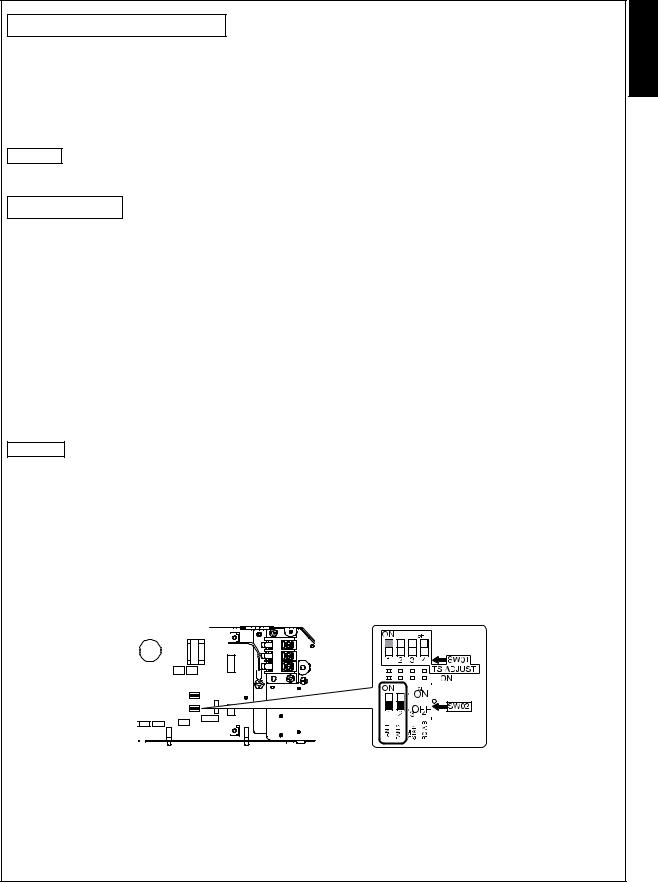
How to set the High ceiling switch
•Remove the cover of the electric parts box by taking off the mounting screws (3 positions) and pushing the hooking section. (The cover of the electric parts box remains hanged to the hinge.)
•There are the selector switches (SW02) on the P.C. board of the electric parts box.
No.1 and No.2 of the selector switches (SW02) are provided to select the height of the ceiling. According to the ceiling height in the following table, select No.1 or No.2 of the selector switches (SW02).
REMARK
• When using the high ceiling (1) or (2), cold air may be felt due to the temperature drop of discharge air.
Height list of ceiling possible to be installed
Model RAS- |
|
M10SMUV-E |
M13SMUV-E |
|
|
|
M16SMUV-E |
|
SW02 |
||||||||||||||||||
|
M10SMUCV-E |
M13SMUCV-E |
|
|
|
M16SMUCV-E |
No.1 |
|
No.2 |
||||||||||||||||||
|
|
|
|
|
|
|
|
|
|
||||||||||||||||||
|
|
|
|
|
|
|
|
|
|
|
|
|
|
|
|
|
|
|
|
|
|
|
|
|
|
|
|
Standard (Factory setting) |
|
2.5 to 2.7 m |
2.5 to 2.7 m |
|
|
|
2.5 to 2.9 m |
OFF |
|
OFF |
|||||||||||||||||
|
|
|
|
|
|
|
|
|
|
|
|
|
|
|
|
|
|
|
|
|
|
|
|
|
|
|
|
High ceiling (1) |
|
|
|
|
— |
— |
|
|
|
2.9 to 3.2 m |
ON |
|
OFF |
||||||||||||||
|
|
|
|
|
|
|
|
|
|
|
|
|
|
|
|
|
|
|
|
|
|
|
|
|
|
|
|
High ceiling (2) |
|
|
|
|
— |
— |
|
|
|
3.2 to 3.5 m |
ON |
|
ON |
||||||||||||||
|
|
|
|
|
|
|
|
|
|
|
|
|
|
|
|
|
|
|
|
|
|
|
|
|
|
|
|
|
|
|
|
|
|
|
|
|
|
|
|
|
|
|
|
|
|
|
|
|
|
|
|
|
|
|
|
|
|
|
|
|
|
|
|
|
|
|
|
|
|
|
|
|
|
|
|
|
|
|
|
|
|
|
|
|
|
|
|
|
|
|
|
|
|
|
|
|
|
|
|
|
|
|
|
|
|
|
|
|
|
|
|
|
|
|
|
|
|
|
|
|
|
|
|
|
|
|
|
|
|
|
|
|
|
|
|
|
|
|
|
|
|
|
|
|
|
|
|
|
|
|
|
|
|
|
|
|
|
|
|
|
|
|
|
|
|
|
|
|
|
|
|
|
|
|
|
|
|
|
|
|
|
|
|
|
|
|
|
|
|
|
|
|
|
|
|
|
|
|
|
|
|
|
|
|
|
|
|
|
|
|
|
|
|
|
|
|
|
|
|
|
|
|
|
|
|
|
|
|
|
|
|
|
|
|
|
|
|
|
|
|
|
|
|
|
|
|
|
|
|
|
|
|
|
|
|
|
|
|
|
|
|
|
|
|
|
|
|
|
|
|
|
|
|
|
|
|
|
|
|
|
|
|
|
|
|
|
|
|
|
|
|
|
|
|
|
|
|
|
|
|
|
|
|
|
|
|
|
|
|
|
|
|
|
|
|
|
|
|
|
|
|
|
|
|
|
|
|
|
|
|
|
|
|
|
|
|
|
|
|
|
|
|
|
|
|
|
|
|
|
|
|
|
|
|
|
|
|
|
|
|
|
|
|
|
|
|
|
|
|
|
|
|
|
|
|
|
|
|
|
|
|
|
|
|
|
|
|
|
|
|
|
|
|
|
|
|
|
|
|
|
|
|
|
|
|
|
|
|
|
|
|
|
|
|
|
|
|
|
|
|
|
|
|
|
|
|
|
|
|
|
|
|
|
|
|
|
|
|
|
|
|
|
|
|
|
|
|
|
|
|
|
|
|
|
|
|
|
|
|
|
|
|
|
|
|
|
|
|
|
|
|
|
|
|
|
ENGLISH
5 |
EN |
 Loading...