


Toshiba RAV-105KH-E, RAV-164AH-PE, RAV-134AH-PE, RAV-135KH-E, RAV-165KH-E INSTALLATION MANUAL
...AIR CONDITIONER |
SPLIT TYPE SYSTEM |
|
|
||
CONDITIONNEUR D’AIR |
TYPE SPLIT SYSTEM |
|
KLIMAANLAGE |
SPLIT SYSTEM |
|
ACONDICIONADOR DE AIRE |
TIPO SPLIT |
|
CONDIZIONATORE D’ARIA |
TIPO SPLIT |
|
AIRCONDITIONER |
SPLIT MODEL |
|
SISTEMA DE AR CONDICIONADO |
TIPO SPLIT |
|
AIR CONDITIONER |
SPLIT TYPE SYSTEM |
|
INSTALLATION INSTRUCTIONS |
GB |
INSTRUCTIONS D’INSTALLATION |
F |
INSTALLATIONSANLEITUNG |
D |
INSTRUCCIONES DE INSTALACIÓN |
E |
ISTRUZIONI PER L’INSTALLAZIONE |
I |
INSTALLATIEVOORSCHRIFTEN |
NL |
INSTRUÇÕES PARA INSTALAÇÃO |
P |
INSTALLATION INSTRUCTIONS |
GR |
HEAT PUMP TYPE |
INDOOR UNITS |
OUTDOOR UNITS |
TYPE POMPE A CHALEUR |
UNITES INTERIEURES |
UNITES EXTERIEURES |
WÄRMEPUMPENMODELL |
INNENGERÄTE |
AUSSENGERÄTE |
TIPO A POMPA DI CALORE |
UNITÀ INTERNE |
UNITÀ ESTERNE |
MODELO BOMBA DE CALOR |
UNIDADES INTERIORES |
UNIDADES EXTERIORES |
WARMTEPOMP MODEL |
BINNENDELEN |
BUITENDELEN |
BOMBA DE CALOR |
UNIDADE INTERIOR |
UNIDADE EXTERIOR |
HEAT PUMP TYPE |
INDOOR UNITS |
OUTDOOR UNITS |
H F C
RAV-105KH-E |
SUPER MULTI |
RAV-135KH-E |
RAV-134AH-PE |
RAV-165KH-E |
RAV-164AH-PE |
RAV-265KH-E |
RAV-264AH/AH8-PE |
1074007802

INSTALLATION INSTRUCTIONS
Please read these instructions carefully before starting the installation.
This equipment should only be installed by suitably trained operatives.
In all cases ensure safe working practice: Observe precautions for persons in the vicinity of the works.
Ensure that all local, national and international regulations are satisfied.
Check that the electrical specifications of the unit meet the requirements of the site.
Carefully unpack the equipment, check for damage or shortages. Please report any damage immediately.
These units comply with EU Directives:
73/23/EEC (Low Voltage Directive) and 89/336/EEC (Electromagnetic Compatibility). Accordingly, they are designated for use in commercial and industrial environments.
Operating conditions
OUTDOOR TEMPERATURE |
-2 ~ 43° C |
COOLING |
|
|
|
-10 ~ 21° C |
HEATING |
ROOM TEMPERATURE |
18 ~ 32° C |
COOLING |
|
|
|
15 ~ 29° C |
HEATING |
ROOM HUMIDITY |
<80% |
COOLING |
|
|
|
|
|
Key to model names
Throughout this booklet, various types of indoor units will be referred to by model codes. Details are shown in the table below:
UNIT DESCRIPTION |
HEAT PUMP CODE |
WALL MOUNTED TYPE |
KH (dual remote controller option) |
|
|
2
CONTENTS |
|
Installation Instructions, Operating Conditions & Key to Model Names ........................................... |
2 |
Accessories Included ............................................................................................................................. |
3 |
Outdoor Unit Location, Precautions, Service Space, Mounting ......................................................... |
4–6 |
Indoor Unit Location, Precautions, Service and Installation Space .................................................... |
7–9 |
Drain Piping, Piping and Drain Hose Location, Drainage ................................................................. |
10-11 |
Drainage Check, Trial Run, Wired Remote Controller, Infra-Red Remote Controller ........................ |
12 |
Refrigerant Piping, Precautions, Material and Sizes ............................................................................ |
13 |
Permissible Piping Length and Head, Pipework Installation, System Purging .................................. |
13 |
Additional Refrigerant, Heat Insulation, Pressure Measurement ....................................................... |
14 |
Electrical Wiring, Precautions, Power Supply Specifications and Wiring ............................................. |
15 |
Wiring Between Units, Connecting the Remote Controller and Group Control ............................. |
16-17 |
Remote Controller, Installation of Remote Controllers, Heat Pump AI Models ..................................... |
18 |
Wiring of two Remote Controllers, Installation of AI Room Remote Controllers ........................... |
19-20 |
Installation of Infra-Red Remote Controllers, Infra-Red Remote Controller Mounting ....................... |
21 |
Improving System Efficiency, Air Flow Direction Adjustment, Increasing Heating Effect .................... |
22 |
Heat Pump Twin Set-up ................................................................................................................... |
23-24 |
Final Installation Checks, Environment .............................................................................................. |
25 |
Passer à la page 26 pour lire le manuel d’installation en français. Die deutsche Installationsanleitung finden Sie auf Seite 50.
Por favor, vaya a la página 74 para seguir las instrucciones del manual de instalacíon en lengua española. Il manuale d’installazione italiano è a pagina 98.
Zie bladzijde 122 voor de Nederlandse Installatievoorschriften. See page 146 for the Portuguese Installation Instructions.
See page 170 for the Greek Installation Instructions.
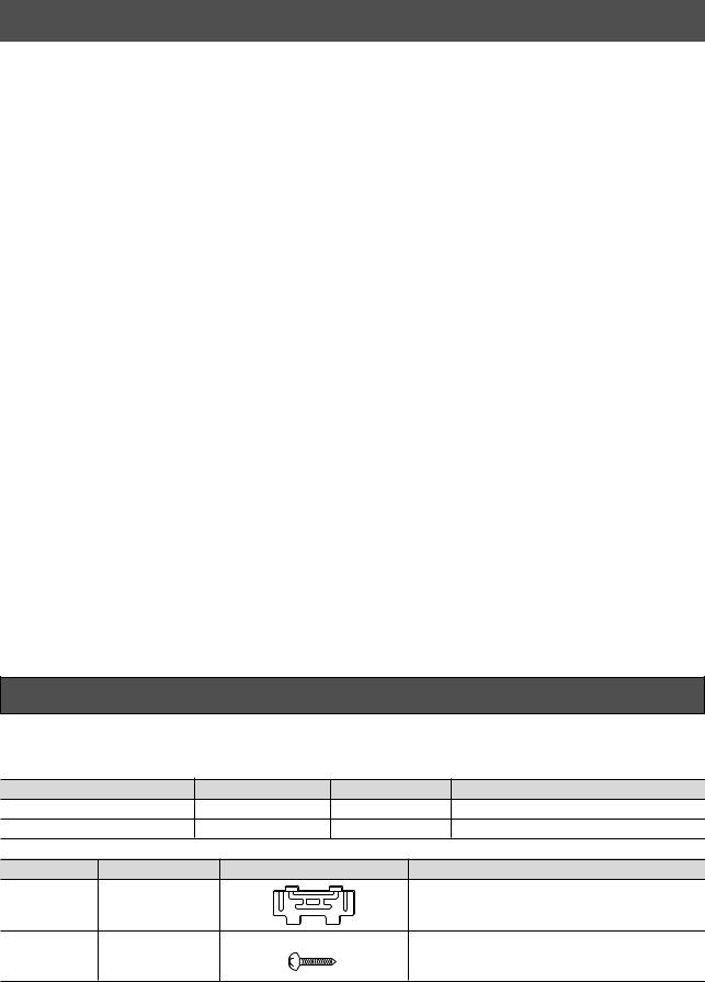
ACCESSORIES INCLUDED
KH units
DESCRIPTION |
|
QUANTITY |
DIAGRAM |
APPLICATION |
Owner’s Manual |
|
1 |
- |
For use by customers |
Installation instructions |
1 |
This book |
- |
|
PART NO. |
QUANTITY |
DIAGRAM |
PART NAME |
|
1 |
1 |
|
Installation plate |
|
2 |
8 |
|
Mounting screw ø 4 mm x 25 mm long |
|
3
OUTDOOR UNIT LOCATION
Precautions
Avoid installing the outdoor unit in the following locations:
Where there is danger of flammable gas leakages.
Where there are high concentrations of oil.
Where the atmosphere contains an excess of salt (as in coastal areas). The air conditioner is prone to failure when used under this condition unless special maintenance is provided.
Where the airflow from the outdoor unit may cause annoyance.
Where the operating noise of the outdoor unit may cause annoyance.
Where the foundation is not strong enough to fully withstand the weight of the outdoor unit.
Where the water drainage may cause a nuisance or a hazard when frozen.
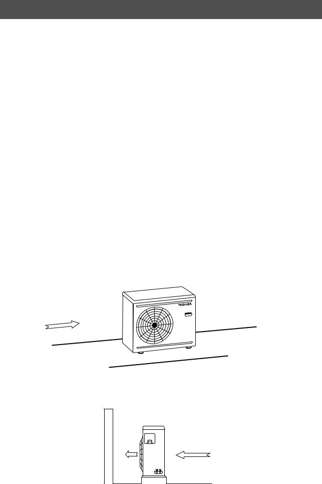
Where strong winds may blow against the air outlet of the outdoor unit.
(The high pressure switch could be tripped if a strong wind should blow against the air outlet during cooling operation). Where this condition is likely to be present, protect the outdoor unit against winds, for example by:
Installing the outdoor unit in parallel with the building so that it can be protected by other buildings:
 Building
Strong wind
Installing the outdoor unit with the air outlet facing the wall, such as on an exposed rooftop:
Wall Airflow
Strong wind
Rooftop
4
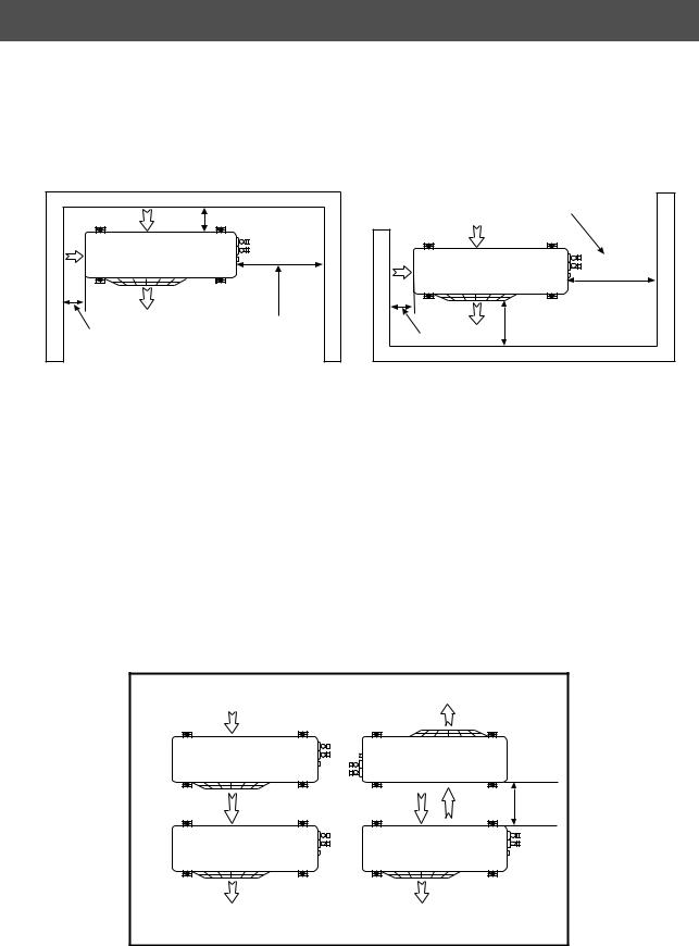
OUTDOOR UNIT LOCATION
Service Space
Ensure that there is sufficient space around the outdoor unit for operation, installation and servicing;
Any obstructions of the airflow must be at least 300 mm from the front of the unit;
All dimensions are minimum.
150 mm |
|
|
or more |
|
|
|
500 mm or more |
|
A: mm or more |
(Wiring and |
|
piping space) |
||
(see table below) |
||
|
Air inlet facing the wall
(Wiring and piping space) |
500 mm or more |
300 mm or more |
A: mm or more |
(see table below) |
Air outlet facing the wall
Model |
A (mm) |
RAV-134AH-PE |
100 |
|
|
RAV-164AH-PE |
100 |
|
|
RAV-264AH/AH8-PE |
100 |
|
|
Mounting
Do not allow units to be situated so that outlet air from one unit is discharged directly into the intake of another unit as indicated below:
300 mm |
minimum |
|
Airflow Path |
|
5
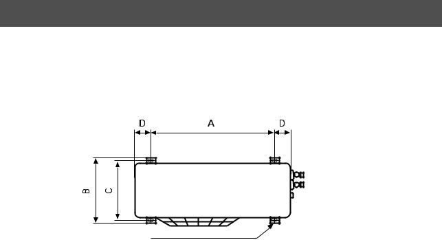
OUTDOOR UNIT LOCATION
Mounting (continued)
Secure the outdoor unit to a sturdy and flat foundation using four anchor bolts. The anchor bolt pitch is shown in the diagram below:
4 x (12 mm x 18 mm) Slots
Model |
A |
B |
C |
D |
|
mm |
mm |
mm |
mm |
RAV-134AH-PE |
790 |
364 |
340 |
45 |
|
|
|
|
|
RAV-164AH-PE |
790 |
364 |
340 |
45 |
|
|
|
|
|
RAV-264AH/AH8-PE |
790 |
364 |
340 |
45 |
|
|
|
|
|
In areas subject to heavy snowfalls, protect the outdoor unit from snow as follows:
(i)Install the unit on a stand which will keep the unit above the level of the standing snow.
(ii)The stand must facilitate water drainage.
(iii)Install snow protection hoods over the air intake and outlet. Ensure that the airflow is not affected.
Failure to take adequate measures in this respect may result in the unit malfunctioning.
6

INDOOR UNIT LOCATION
Location Precautions
Avoid installing the indoor unit in the following locations:
Where there is danger of flammable gas leakages.
Where there are high concentrations of oil.
Where the atmosphere contains an excess of salt (as in coastal areas). The air conditioner is prone to failure when used under this condition unless special maintenance is provided.
Where high concentrations of organic solvent are present.
Where a machine that generates a high frequency is operated.
Where the unit will not be horizontal.
Where the ceiling height is more than 3 m.
Where the floor/wall/ceiling structure is unable to support the weight of the unit.
Where it is not possible to fix the unit hangers, e.g. window glass.
Locate the unit so as to provide uniform circulation of chilled air.
Avoid locating the unit as shown in the -marked figures below:
|
|
|
|
|
|||
Good location |
|
Bad location |
|
Bad location |
|||
Evenly cooled |
Shaded area not well cooled |
Shaded area not well cooled |
|||||
|
|
|
|
|
|
|
|
|
|
|
|
|
|
|
|
|
|
|
|
|
|
|
|
|
|
|
|
|
|
|
|
If a good location is not possible, use a fan to circulate the air evenly throughout the room.
7

INDOOR UNIT LOCATION
For rear left and side pipe exit
Wall
Insert the cushion between the indoor unit and wall, and lift indoor unit to make work easier.
170 |
mm |
|
or |
|
|
|
more |
|
mmormore |
Hook |
|
||
65 |
|
Installation |
||
|
|
plate |
|
|
|
|
|
|
|
|
|
|
|
|
|
|
170 |
|
|
Hook |
|
or |
|
mm |
|
|
|
more |
|
Insulate the refrigerant pipes separately with insulation, not together.
Min. 6 mm thick heat resisting polyethylene foam
Do not allow the drain hose to sag.
Cut the piping hole sloped slightly
Make sure to run the drain hose sloped downward.
Air |
filter |
|
Pipe insulation
Mounting the Installation Plate
For installation of the indoor unit, use the paper template included.
The auxiliary piping can be connected the left, rear left, rear, right or bottom.
Right
Rear
Bottom |
Left |
|
Rear left |
||
|
|
|
55 |
65 |
|
Hook |
|
|
170 |
|
|
|
|
|
|
|
120 |
|
|
Installation plate |
Hook |
|
Hook |
|
Thread |
|
|
|
Pipe hole |
Pipe hole |
|
|
Indoor unit |
Weight |
|
Mounting screw
When the installation plate is directly mounted on the wall
1.Securely fix the installation plate to the wall by screwing it through the upper and lower fixing holes.
2.To mount the installation plate on a concrete wall with anchor bolts, utilize the anchor bolt holes as illustrated in the above figure.
3.Install the installation plate horizontally in the wall.
CAUTION:
When installing the installation plate with mounting screw, do not use the anchor bolt hole. Otherwise the unit may fall down and result in personal injury and property damage.
Anchor bolt
5 mm ø hole
Projection 15 mm or less 
Mounting screw ø4 x 25 mm
 Clip anchor (local parts)
8
 Loading...