


FILE NO. A05-012
OWNER’S MANUAL/INSTALLATION MANUAL
R410A
System air conditioner
The indoor unit in Super Heat Recovery Multi System is common to one in Super Modular Multi System air conditioner. Therefore refer to the service manuals for A03-009, A03-010, and A03-011 separately issued.
Heat Recovery Type
Indoor Unit
<4-way Air Discharge Cassette Type>
MMU-AP0091H, AP0121H, AP0151H, MMU-AP0181H, AP0241H, AP0271H, MMU-AP0301H, AP0361H, AP0481H MMU-AP0561H
Outdoor Unit
<Inverter Unit>
MMY-MAP0802FT8 MMY-MAP1002FT8 MMY-MAP1202FT8
<2-way Air Discharge Cassette Type>
MMU-AP0071WH, AP0091WH, AP0121WH, MMU-AP0151WH, AP0181WH, AP0241WH, MMU-AP0271WH, AP0301WH, AP0481WH*
* CHINA market only
<1-way Air Discharge Cassette Type>
MMU-AP0071YH, AP0091YH, AP0121YH, MMU-AP0151SH, AP0181SH, AP0241SH, MMU-AP0152SH, AP0182SH, AP0242SH
Flow Selector Unit (FS unit)
RBM-Y1122FE
RBM-Y1802FE
RBM-Y2802FE
<Concealed Duct Standard Type>
MMD-AP0071BH, AP0091BH, AP0121BH, AP0151BH, MMD-AP0181BH, AP0241BH, AP0271BH, AP0301BH, MMD-AP0361BH, AP0481BH, AP0561BH
<Concealed Duct High Static Pressure Type>
MMD-AP0181H, AP0241H, AP0271H,
MMD-AP0361H, AP0481H
<Slim Duct Type>
MMD-AP0071SPH, AP0091SPH, AP0121SPH, MMD-AP0151SPH, AP0181SPH
<Under Ceiling Type>
MMC-AP0151H, AP0181H, AP0241H,
MMC-AP0271H, AP0361H, AP0481H
<High Wall Type>
MMK-AP0071H, AP0091H, AP0121H, MMK-AP0151H, AP0181H, AP0241H, MMK-AP0072H, AP0092H, AP0122H
<Floor Standing Cabinet Type>
MML-AP0071H, AP0091H, AP0121H, MML-AP0151H, AP0181H, AP0241H
<Floor Standing Concealed Type>
MML-AP0071BH, AP0091BH, AP0121BH, MML-AP0151BH, AP0181BH, AP0241BH
<Floor Standing Type>
MMF-AP0151H, AP0181H, AP0241H,AP0271H, MMF-AP0361H, AP0481H, AP0561H
PRINTED IN JAPAN, Aug, 2005 ToMo

ADOPTION OF NEW REFRIGERANT
This Air Conditioner is a new type which adopts a new refrigerant HFC (R410A) instead of the conventional refrigerant R22 in order to prevent destruction of the ozone layer.
Thank you very much for purchasing TOSHIBA Air Conditioner.
Please read this owner's manual carefully before using your Air Conditioner.
• Be sure to obtain the “Owner’s manual” and “Installation manual” from constructor (or dealer).
Request to constructor or dealer
Please clearly explain the contents of the Owner’s manual and hand over it.
ADOPTION OF NEW REFRIGERANT
This Air Conditioner is a new type which adopts a new refrigerant HFC (R410A) instead of the conventional refrigerant R22 in order to prevent destruction of the ozone layer.
Thank you very much for purchasing TOSHIBA Air Conditioner.
•This manual describes the installation method at the outdoor unit side.
•Before installation, please read this Manual thoroughly to perform correct installation.
•For pipe connection for the indoor and outdoor units, flow selector unit Y-shape branching joint or branch header required sold separately. Select it according to the capacity.
•For pipe connection between the outdoor units, T-shape branching joint which is sold separately is required.
ADOPTION OF NEW REFRIGERANT
This SUPER HRM Air Conditioner is a new type which adopts a new refrigerant HFC (R410A) instead of the conventional refrigerant R22 in order to prevent destruction of the ozone layer.
Be sure to use an indoor or outdoor unit in combination with the new refrigerant.
Thank you very much for purchasing TOSHIBA SUPER HRM Air conditioner.
Please read this manual carefully before using your Flow Selector unit.
•When installing an indoor or outdoor unit, follow the installation manual supplied with the unit.
•To connect the Flow Selector unit to an outdoor unit with pipes, a branching joint or header is required. Choose one according to the capacity of the units.
•Nitrogen gas is filled in the selection unit. Be careful when removing flare nuts.
|
CONTENTS |
|
OWNER’S MANUAL (EH99920601-R) |
|
|
PRECAUTIONS FOR SAFETY ........................................................................................................... |
1 |
|
NAME OF EACH PART ....................................................................................................................... |
3 |
|
PARTS NAME OF REMOTE CONTROLLER ...................................................................................... |
6 |
|
CORRECT USAGE .............................................................................................................................. |
8 |
|
ADJUSTMENT OF WIND DIRECTION ............................................................................................... |
9 |
|
TIMER OPERATION .......................................................................................................................... |
16 |
|
INSTALLATION .................................................................................................................................. |
17 |
|
MAINTENANCE ................................................................................................................................. |
18 |
|
AIR CONDITIONER OPERATIONS AND PERFORMANCE ............................................................ |
22 |
|
RE-INSTALLATION ........................................................................................................................... |
23 |
|
WHEN THE FOLLOWING SYMPTOMS ARE FOUND ...................................................................... |
24 |
|
INSTALLATION MANUAL <OUTDOOR UNIT> (EH99842501-Q) |
|
|
|
VOLUME-1 |
|
ACCESSORY PARTS ........................................................................................................................ |
26 |
|
SAFETY CAUTION ............................................................................................................................ |
26 |
|
1 |
INSTALLATION OF NEW REFRIGERANT AIR CONDITIONER ............................................ |
28 |
2 |
SELECTION OF INSTALLATION PLACE ................................................................................ |
29 |
3 |
OUTDOOR UNIT CARRYING IN ............................................................................................. |
30 |
4 |
INSTALLATION OF OUTDOOR UNIT ..................................................................................... |
31 |
5 |
REFRIGERANT PIPING ........................................................................................................... |
33 |
INSTALLATION MANUAL <OUTDOOR UNIT> (EH99842601-Q) |
|
|
|
VOLUME-2 |
|
SAFETY CAUTION ............................................................................................................................ |
43 |
|
6 |
ELECTRIC WIRING .................................................................................................................. |
44 |
7 |
ADDRESS SETUP ................................................................................................................... |
50 |
8 |
SETTING WHEN CONNECTING MULTIPLE INDOOR UNITS TO A FS UNIT ....................... |
59 |
9 |
HOW TO SET UP THE COOLING ONLY INDOOR UNIT ......................................................... |
60 |
10 |
TEST OPERATION ................................................................................................................... |
61 |
11 |
TROUBLESHOOTING ............................................................................................................. |
63 |
INSTALLATION MANUAL <FLOE SELECTOR UNIT> (EH99842401-Q) |
|
|
Accessory parts and Parts to be procured locally ....................................................................... |
65 |
|
1 |
PRECAUTIONS FOR SAFETY ................................................................................................ |
65 |
2 |
INSTALLATION OF NEW REFRIGERANT AIR CONDITIONER ............................................ |
67 |
3 |
SELECTION OF INSTALLATION PLACE ................................................................................ |
68 |
4 |
INATALLATION OF FLOW SELECTOR UNIT ......................................................................... |
70 |
5 |
REFRIGERANT PIPING ........................................................................................................... |
72 |
6 |
ELECTRIC WORK .................................................................................................................... |
76 |
OWNER’S
INSTALLATION OUTDOOR (VOLUME-1)
INSTALLATION OUTDOOR (VOLUME-2)
INSTALLATION FLOW SELECTOR UNIT
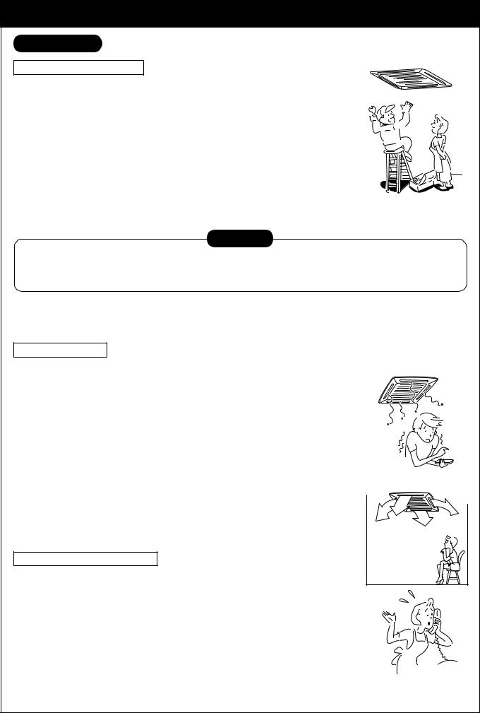
PRECAUTIONS FOR SAFETY
 WARNING
Warning on installation
Be sure to leave the installation work to the dealer or a store specializing.
The exclusive knowledge and technology are required for installation work.
Do not perform installation by yourself. If an incomplete installation is performed, a fire, electric shock, injury, or water leakage may be caused.
Be sure to use the products sold separately which are specified by us.
For the products sold separately, be sure to use those specified by us. Otherwise, a fire, electric shock, or water leakage may be caused. For installation work, leave it to special engineer.
When installing the units in a small room, take measures so that the refrigerant will not exceed the critical concentration if it leaks.
CAUTION
Related to countermeasures against the critical concentration, perform the installation work upon consultation with the dealer. If the refrigerant leaks and exceeds the critical concentration, oxygen deficiency may be caused.
Check whether earthing work is performed correctly.
A grounding is necessary. If the earthing work is incompletely, an electric shock may be caused. (For details, conform to the local regulation in each area.)
Warning on use
Do not expose your body directly in cool air for a long time, or do not cool you excessively.
It causes the worse of physical condition or trouble on health.
Never insert a finger or bar into the air inlet port or air outlet port of air.
Since the fan rotates in high speed inside of the unit, an injury may be caused.
When a trouble (burnt smell, etc.) is felt, stop the operation, turn off the power switch, and contact the dealer who you have
purchased the air conditioner.
If keeping operation as the air conditioner is defective, a fire, electric shock, or trouble may be caused.
Do not use “Super HRM” for other than personal usage where the ambient temperature may go down below –5°C.
For example, OA equipment/Electric device/Food/Animals and plants/Art object.
Warning on moving/repair
Never modify the air conditioner.
A fire or electric shock may be caused.
For repair, leave it to the dealer which you have purchased the air conditioner.
If an incomplete repair is performed, a fire or electric shock may be caused.
When moving or re-installing the air conditioner, contact the dealer which you have purchased the air conditioner or the special engineer.
If an incomplete installation is performed, a fire, electric shock, injury, or water leakage may be caused.
1
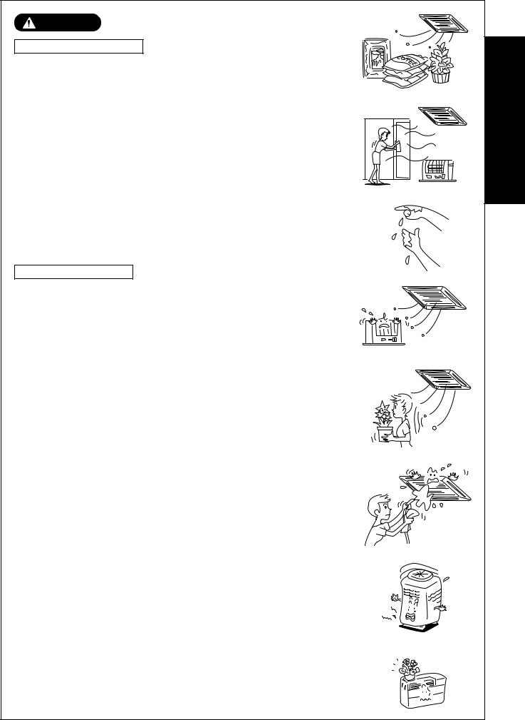
CAUTION
Caution on installation
Check the drain pipes are installed so that they can drain water securely.
If the piping is incomplete, water leakage occurs resulted in moisture on furniture.
Check the earth leakage breaker is attached.
It is necessary to attach an earth leakage breaker. Otherwise, it causes an electric shock.
Check the air conditioner is installed at a place where flammable gas will not leak.
If gas leaks and accumulates in the unit surroundings, an outbreak of fire may be caused.
Check the outdoor unit is fixed on the base.
If it is not fixed securely on the base, an accident such as falling may be caused.
Check fixing method
Do not clean the air conditioner with water.
An electric shock may be caused.
Do not put the combustible devices at a place where air from the air conditioner flows directly.
Imperfect combustion of the combustible devices may be caused.
Diligently ventilate the room when operating the air conditioner with the combustible devices.
If ventilation is incomplete, shortage of oxygen may be caused.
Check the installation plate, etc. is not damaged by use for a long time.
If leaving them damaged, the unit may fall resulted in injury, etc.
Do not put plants and animals at a place where air from the air conditioner flows directly.
Cause to affect on plants and animals may generate.
Do not put flammable spray, etc. near the air conditioner, or do not spray directly on the air conditioner.
A fire may be caused.
Do not put vessels including water such as a vase on the unit.
Moisture floods in the unit, the electric isolation deteriorates, and an electric shock may be caused.
Do not handle the switches with wet hands.
An electric shock may be caused.
Do not use the air conditioner for special purpose such as storage of foods, plants and animals, precise equipment, and art works.
Deterioration of quality may be caused.
2
OWNER’S

NAME OF EACH PART
Indoor unit
[4-way Air Discharge Cassette Type]
Air outlet/Air outlet flap
Select air blow direction in cooling or heating operation each.
Earth screw
It is included in the electric parts box.
Clip |
The clip is to open/close the air inlet grille.
2-way discharge/3-way discharge
2-way discharge or 3-way discharge can be selected according to the shape or arrangement of the room.
For details, consult with the dealer which you have purchased the air conditioner.
 Air filter
Removes dust and trash.
(Air filter is provided in the air grille.)
Air inlet grille
Air in the room is sucked from here.
[2-way Air Discharge Cassette Type]
Earth screw |
|
|
Air outlet/Air outlet flap |
||
|
|||||
It is included in the electric parts box. |
|
|
Select air blow direction in cooling or |
||
Center panel |
|
|
|
|
heating operation each. |
|
|
|
|
|
|
|
|
|
|
|
|
|
|
|
|
|
|
|
|
|
|
|
|
Air inlet |
Air filter |
Air in the room is |
Removes dust and trash. |
sucked from here. |
(Air filter is provided in the center panel.) |
[1-way Air Discharge Cassette Type]
MMU-AP0071YH to AP0121YH |
MMU-AP0151SH to AP0241SH |
|||||||||
Air outlet/Air outlet flap |
|
|
|
Earth screw |
|
|
|
|||
Select air blow direction in |
|
|
It is included in the electric parts box. |
|
||||||
cooling or heating operation each. |
|
|
Air outlet/Air outlet flap |
|
||||||
Earth screw |
|
|
|
|
|
|
||||
|
|
|
|
Select air blow direction in cooling |
|
|||||
It is included in the |
|
|
|
|||||||
|
|
or heating operation each. |
|
|||||||
electric parts box. |
|
|
|
|||||||
|
|
|
|
|
|
|
||||
|
|
|
|
|
||||||
|
|
|
|
|
|
|
|
|
|
|
|
|
|
|
|
|
|
|
|
|
|
|
|
|
|
|
|
|
|
|
|
|
|
|
|
|
|
|
|
|
|
|
|
|
|
|
|
|
|
|
|
|
|
|
|
|
|
|
|
|
|
|
|
|
|
Air inlet grille |
|
|
|
|
Air inlet grille |
|
|
|
|
|
|
|
|
|
|||
|
|
|
|
|
|
|||
|
|
Air in the room is sucked |
||||||
|
|
|||||||
Air in the room is sucked from here. |
||||||||
from here. |
||||||||
Air filter |
|
Air filter |
|
|
|
|
|
||
Removes dust and trash. |
Removes dust and trash. |
|||
(Air filter is provided in the air inlet grille.) |
(Air filter is provided in the air inlet grille.) |
|||
MMU-AP0152SH, AP0182SH, AP0242SH
Button
Button to open/close suction port
Air filter
Removes dust or trash. (Provided on the suction port.)
Suction port
Sucks air inside of the room from here.
Earth screw
It is included in the electric parts box.
Air outlet/Air outlet flap
Change the direction of the air to be discharged according to cool/heat mode.
Air filter
Removes dust or trash. (Provided on the suction port.)
Sold Separately Parts
controllerremoteMain |
AMT31E-RBC |
|
|
|
|
|
CODE No. |
|
|
SET DATA SETTING TEST |
|
|
|
|
|
|
|
|
|
UNIT |
No. |
|
|
|
|
H |
|
R.C. |
|
No. |
|
|
|
|
|
|
|
|
|
|
|
TEMP. |
|
|
|
|
ON / OFF |
|
|
|
TIMER SET |
|
FAN |
MODE |
|
|
|
|
TIME |
SWING/FIX |
VENT |
||
|
|
FILTER |
|
|
|
|
|
|
|
RESET TEST |
SET |
CL |
|
UNIT |
|
controllerremote- |
AS21E2-RBC |
TEST |
˚C |
|
|
SETTING |
|
Sub |
|
|
|
TCB-AX21E2 RBC-AX22CE2 RBC-AX21U(W)-E2
Wireless remote controller kit
3

[Concealed Duct Type]
Air outlet flange
Discharge duct is connected.
Air filter
Removes dust and trash.
(Air filter is provided in the air inlet grille.)
Earth screw
Earth screws are provided in the electric parts box.
Air inlet
Air in the room is sucked from here.
[Concealed Duct, High Static Pressure Type]
Air outlet |
|
|
|
Air inlet |
|
|
|||
Discharge duct is connected. |
|
|
Suction duct is connected. |
|
Earth screw |
|
|
|
|
|
|
|
|
|
|
|
|
|
|
|
|
|
|
|
|
Drain pan |
Earth screws are provided in the electric parts box.
[Slim Duct Type]
Air inlet
Suction duct is connected.
Air filter
(Air filter is not provided to some models in the series.)
[Under Ceiling Type]
Button
Button to open/close the suction port
Air filter
Removes dust or trash. (Provided on the suction port.)
[High Wall Type]
MMK-AP0071H to AP0241H
Air inlet grille
Air in the room is sucked from here.
Air filter
Removes dust and trash. (Air filter is provided in the air inlet grille.)
Earth screw
It is included in the electric parts box.
Air outlet
Discharge duct is connected.
Air inlet port
The air in the room is sucked in from this port.
 Earth screw
Earth screws are provided in the electric parts box.
Air outlet/Air outlet flap
Change the direction of the air to be discharged according to cool/heat mode.
Earth screw
Earth screws are provided in the electric parts box.
Air outlet/Air outlet flap
Change the direction of the air to be discharged according to cool/heat mode.
MMK-AP0072H to AP0122H
Air inlet grille
Air in the room is sucked from here.
Air filter
Removes dust and trash. (Air filter is provided in the air inlet grille.)
Earth screw
Earth screws are provided in the electric parts box.
Air outlet/Air outlet flap
Change the direction of the air to be discharged according to cool/heat mode.
timerWeekly |
EXW21E2-RBC |
|
SuMoTuWeTh Fr Sa |
|
|
PROGRAM1 |
|
|
|
PROGRAM2 |
ERROR |
|
|
|
|
|
|
PROGRAM3 |
|
|
|
WEEKLY TIMER |
|
controllerremoteCentral SC642TLE2-TCB |
ALL |
ZONE |
|
|
|
ZONE |
|
|
|
|
GROUP |
|
|
|
|
|
|
|
CODE |
|
1234 |
|
No. |
|
|
UNIT No. |
TEST |
||
|
SET DATA |
R.C. |
No. |
|
|
SETTING |
|
||
|
|
|
|
GROUP |
|
SELECT |
ZONE |
||
|
|
|
CL SET |
|
4
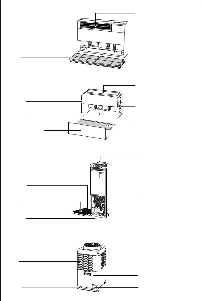
[Floor Standing Cabinet Type]
Air filter
Removes dirt or dust.
(It is included in the suction port.)
[Floor Standing Concealed Type]
Earth screw
It is prepared in the electric parts box.
Air inlet port
Sucks air inside of the room from here.
Front panel (Lower side)
[Floor Standing Type]
Horizontal flap/Air outlet port
Exchanges the air direction according to cooling or heating time.
Air inlet port
Sucks air inside of the room from here.
Air filter
Removes dirt or dust.
Earth screw
It is prepared in the electric parts box.
Air outlet/Air outlet flap
Exchanges the air direction according to cooling or heating time.
 Earth screw
It is prepared in the electric parts box.
 Air inlet port
Sucks air inside of the room from here.
Air outlet port
Drain pan (With drain filter)
This accessory is installed at the local site.
Air filter
Removes dirt or dust.
(It is included in the suction port.)
Fixing metal holder
Vertical flap
The air can be automatically discharged rightward/leftward at stated periods.
Drain pan
Water accumulated in the drain pan is drained from here through the drain pipe.
 Fixing metal holder (Right and left)
Outdoor unit
Air inlet
They are provided at front, rear, left, and right sides.
Fixing leg
 Air outlet (Discharge)
Hot air is discharged when cooling operation is performed. Cold air is discharged when heating operation is performed.
Power source hole
Refrigerant pipe connecting hole
Connecting valve is included inside here.
5
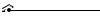
PARTS NAME OF REMOTE CONTROLLER
Display section
In the display example, all indicators are displayed for the explanation. In reality only, the selected contents are indicated.
•When turning on the leak breaker at the first time, [SET DATA] flashes on the display part of the remote controller. While this display is flashing, the model is being automatically confirmed. Accordingly, wait for a while after [SET DATA] display has disappeared, and then use the remote controller.
|
|
CODE No. |
SET DATA SETTING TEST |
|
Display |
|
UNIT No. |
|
H |
R.C. No. |
section |
TEMP. |
|
ON / OFF |
|
TIMER SET |
FAN |
MODE |
Operation |
|
|
|
|
TIME |
SWING/FIX |
VENT |
section |
FILTER |
|
|
|
RESET TEST SET CL |
UNIT |
|
|
7 8 9
2
1
3
4
5
6
15
|
|
CODE No. |
17 |
|
|
|
|
SET DATA SETTING TEST |
|
10 |
|
|
UNIT No. |
16 |
|
|
|
||
H |
R.C. No. |
|
|
|
|
||
|
11 |
|
|
|
|
13 |
|
|
|
12 |
14 |
1 SET DATA display
Displayed during setup of the timer.
2 Operation mode select display
The selected operation mode is displayed.
3 CHECK display
Displayed while the protective device works or a trouble occurs.
4 Timer time display
Time of the timer is displayed.
(When a trouble occurs, the check code is displayed.)
5 Timer SETIN setup display
When pushing the Timer SETIN button, the display of the timer is selected in order of
[OFF] |
|
→ |
[OFF] repeat OFF timer → |
|
|||
[ON] |
|
→ |
No display. |
6 Filter display
If “FILTER  ” is displayed, clean the air filter.
7 TEST run display
Displayed during a test run.
8 Flap position display
(for 4-Way Air Discharge Cassette Type and Under Ceiling Type model only)
Displays flap position.
9 SWING display
Displayed during up/down movement of the flap.
10 Set up temperature display
The selected set up temp. is displayed.
11 Remote controller sensor display
Displayed while the sensor of the remote controller is used.
12
13
14
15
16
17
PRE-HEAT display
Displayed when the heating operation starts or defrost operation is carried out.
While this indication is displayed, the indoor fan stops or the mode enters in LOW.
Operation ready display
Displayed when cooling or heating operation is impossible because the outdoor temperature goes out of the operable range.
No function display
Displayed if there is no function even if the button is pushed.
Air volume select display
The selected air volume mode is displayed.
(AUTO) |
(HIGH) |
(MED.) |
(LOW) |
In the Concealed Duct High Static Pressure type models, [HIGH] only is displayed for the air speed.
Mode select control display
Displayed when pushing “Operation mode select  ” button while the operation mode is fixed to heating or cooling by the system manager of the air conditioner.
Central control display
Displayed when using the remote controller together with the central control remote controller, etc.
If Remote controller is prohibited at the centralcontrol side,  flashes when operating
ON / OFF , MODE , |
/ |
buttons and |
the change is not accepted.
(The contents available to be set up on the remote controller differ according to the central control mode. For details, refer to Owner’s Manual of the central control remote controller.)
6
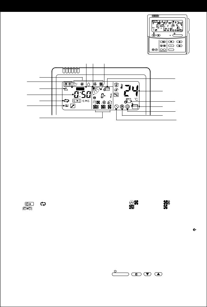
Operation section
Push each button to select a desired operation.
This remote controller can operate the maximum 8 indoor units.
• The details of the operation needs to be set up once, afterward, the air conditioner can be used by pushing
ON / OFF |
button only. |
1 |
7 |
|
|
|
|
|
|
||
|
TEMP. |
|
|
ON / OFF |
8 |
|
10 |
|
|
|
|
|
TIMER SET |
FAN |
MODE |
|
|
|
2 |
9 |
|||
|
TIME |
SWING/FIX |
VENT |
||
|
|
4 |
|||
|
FILTER |
|
|
|
|
|
RESET TEST |
SET CL |
UNIT |
|
6 |
|
5 |
|
|
|
|
|
3 |
|
|
|
|
1 Air volume select button |
|
7 Operation lamp |
|
||
2
3
Selects the desired air volume mode. |
|
Lamp is lit during the operation. Lamp is off |
||
The Concealed Duct High Static Pressure type |
|
when stopped. |
||
models cannot be operated. |
|
Although it flashes when operating the protec- |
||
Timer set button |
|
tion device or abnormal time. |
||
8 |
ON / OFF |
|
||
TIMER SET button is used when the timer is |
button |
|||
|
||||
set up. |
When the button is pushed, the operation |
|
|
||
Check button |
starts, and it stops by pushing the button |
|
again. |
||
The CHECK button is used for the check |
||
When the operation has stopped, the operation |
||
operation. During normal operation, do not |
||
lamp and all the displays disappear. |
||
use this button. |
||
|
4 Fan button
FAN button is used when a fan which is sold on the market or etc. is connected.
•If  is displayed on the remote controller when pushing the FAN button, a fan is not connected.
5 Filter reset button
Resets (Erases) “FILTER  ” display.
6 Wind direction and Swing
UNIT :
If the multiple indoor units are operated by only one remote controller, select the units when the air direction is adjusted.
SWING/FIX :
Set up the auto swing and angle of the flap.
•This function is not provided to Concealed Duct Standard Type, High Static Pressure Type, Floor standing Cabinet Type, Floor Standing Concealed Type, or Slim Duct Type.
9 Operation select button
Selects desired operation mode.
10 Set up temperature button
Adjusts the room temperature.
Set the desired set temperature by pushing  or
or  .
.
OPTION :
Remote controller sensor
Usually the TEMP. sensor of the indoor unit senses the temperature. The temperature on the surrounding of the remote controller can also be sensed.
For details, contact the dealer from which you have purchased the air conditioner.
•In case that one remote controller controls the multiple indoor units, the setup operation is unavailable in group control.
7
CORRECT USAGE
When you use the air conditioner for the first time or when you change the SET DATA value, follow the procedure below. From the next time, the operation displayed on the remote controller will start by pushing the
ON / OFF button only.
Preparation
Turn on the main power switch and/or the leakage breaker.
• When the power supply is turned on, a partition line is displayed on the display part of the remote controller.
*After the power supply is turned on, the remote controller does not accept an operation for approx. 1 minute, but it is not a failure.
REQUIREMENT
• While using the air conditioner, operate it only with ON / OFF button without turning off the main power switch and the leak breaker.
•Do not turn off the leak breaker while the air conditioner is used.
•Turn on the leak breaker 12 hours or more before start of operation after the air conditioner has stopped for a long time.
TEMP. |
|
ON / OFF |
|
1 |
4 |
|
|
3 |
|
|
|
2 |
||
TIMER SET |
FAN |
MODE |
||
TIME |
SWING/FIX |
VENT |
|
|
FILTER |
|
|
|
|
RESET TEST SET CL |
UNIT |
|
|
|
1
2
3
ON / OFF
Push button.
The operation lamp goes on, and the operation starts.
Select an operation mode with the MODE button.
One push of the button, and the display changes in the order shown on the right.
•“DRY  mode” function is not provided to Concealed Duct High Static Pressure Type.
Select air volume with |
FAN |
button. |
|

 AUTO
AUTO 
 HEAT
HEAT 
 DRY
DRY 
 COOL
COOL 
 FAN (Dehumidity)

 AUTO
AUTO 

 HIGH
HIGH 

 MED.
MED. 

 LOW
LOW
One push of the button, and the display changes in the order shown on the right.
•When air volume is “AUTO  ”, air volume differs according to the temperature difference between set temperature and room temperature.
•In DRY  mode, “AUTO
  ” is displayed and the air volume is LOW.
•In heating operation, if the room temperature is not heated sufficiently with volume “LOW  ” operation, select “MED.
  ” or “HIGH
 ” operation.
•The temperature which the temperature sensor detects is one near the air inlet of the indoor unit. Therefore it slightly differs from the room temperature according to the installation status. The setup value is a criterion of the room temperature. (Automatic air speed cannot be selected in FAN mode.)
•Air volume of function is not provided to “Concealed Duct High Static Pressure Type” but air speed “HIGH 
 ” only is displayed.
4 Determine the set up temperature by pushing the “TEMP.  ” or “TEMP.
  ” button.
Stop
Push ON / OFF button.
The operation lamp goes off, and the operation stops.
8
REQUIREMENT
[In Cooling operation]
• The operation starts after approx. 1 minute.
[In Heating operation]
•In heating operation, the fan operation may continue for approx. 30 seconds after the air conditioner has stopped.
•The indoor fan continues preheat operation for 3 to 5 minutes under stop condition, and then blows out
the hot air.
( display on the remote controller display part goes on.)
•When temperature of the room has reached the setup temperature and the outdoor unit stops, the air speed becomes super low and the air volume extremely is lessened.
•In the defrost mode, the fan stops so that cool air is not discharged and PRE-DEF  is displayed.
[In Automatic operation]
•Using the difference between the setup temperature and the room temperature, the heating or cooling operation is automatically performed.
ADJUSTMENT OF WIND DIRECTION
To increase the cooling or heating effect, be sure to use the discharge flap in the different directions in cooling or heating operation.
As the characteristics of the air, the cold air accumulates at lower side and hot air at upper side, respectively.
CAUTION
Set the louver horizontally in cooling operation.
If cooling operation is performed with downward discharge, the surface of the discharge port or louver will be wet with dew, and dewdrop may fall down.
REQUIREMENT
•If heating operation is performed with horizontal discharge, unevenness of temperature may increase in the room.
4-way Air Discharge Cassette Type
•While the air conditioner stops, the discharge flap automatically directs downward.
•While the air conditioner is in ready status for heating, the discharge flap directs upward.
The swinging operation starts after heating ready status has been cleared, but “SWING  ” is displayed on the remote controller even if the status is ready to heating.
[In Cooling operation]
Use the discharge flap with horizontal set point.
[In Heating operation]
Use the discharge flap with downward set point.
9
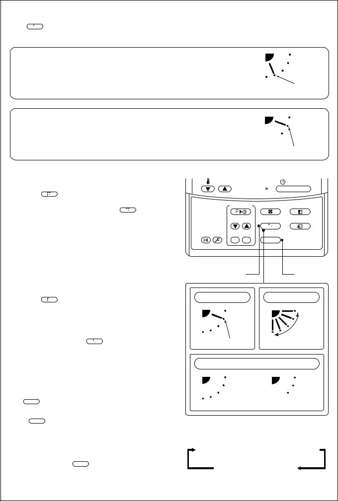
How to set up the air direction
Push SWING/FIX button.
1 Every pushing the button, the air direction changes.
In Heating operation
Set the air outlet flap downward.
If directing it upward, the hot air may not come to the foot.
Initial setup
In Cooling / Dry operation
Set the air outlet flap upward.
If directing it downward, the dew may fall on near the air discharge port or it drips.
How to start swinging
2 Push SWING/FIX button.
Set direction of the air outlet flap to the lowest position and then push SWING/FIX button again.
•[SWING  ] is displayed and the air direction automatically changes upward/downward.
In case when one remote controller controls the multiple indoor units, each indoor unit can be selected and its air direction can be set up.
How to stop swinging
3 Push SWING/FIX button again during swinging of the air outlet flap.
•The air outlet flap can be stopped at the desired position. After then the air direction can be again set up from the uppermost position by pushing SWING/FIX button.
Initial setup
TEMP. |
|
ON / OFF |
TIMER SET |
FAN |
MODE |
TIME |
SWING/FIX |
VENT |
FILTER |
|
|
RESET TEST SET CL |
UNIT |
|
1, 2, 3 |
4 |
In FAN operation |
In all modes |
Series of operation
Initial setup
*While the air outlet flap is set downward in cooling/drying operation, it does not stop. If stopping the air outlet flap which directs downward during swinging, it stops after moving to the 3rd position from the top position.
4 UNIT
• To set up the air direction individually, push UNIT button to display each indoor unit No. in
a group control. Then set up the air direction to a displayed indoor unit.
•If there is no display, all the indoor units can be operated collectively.
• Every pushing UNIT button, the display exchanges as shown in the figure.
Display when stopping the swing
Fan/Heat |
Cool/Dry |
operation |
operation |
No display  Unit No. 1-1
  Unit No. 1-2
Unit No. 1-4  Unit No. 1-3
10
According to the shape or arrangement of the room, the cold air and hot air can be discharged for two directions or three directions. For details, contact the dealer.
INFORMATION
•If cooling operation is performed with downward discharge, dew may fall on surface of the cabinet or the horizontal flap resulted in dripping.
•If heating operation is performed with horizontal discharge, unevenness of temperature may increase in the room.
•Do not move the horizontal flap directly with hands; otherwise a trouble is caused. Select direction of the horizontal flap using flap operation switch on the remote controller. The horizontal flap does not stop immediately even if the switch is pushed. Adjusting the stop position, push the switch.
2-way Air Discharge Cassette Type
[In Cooling operation]
Use the air outlet flap with horizontal set point.
[In Heating operation]
Use the air outlet flap with downward set point.
Setup of air direction and swinging
1 Push SWING/FIX button during operation.
•[SWING  ] is displayed and the air direction automatically changes upward/downward.
In case when one remote controller controls the multiple indoor units, each indoor unit can be selected and its air direction can be set up.
2 Push SWING/FIX button again during swinging of the air outlet flapp.
•The air outlet flap can be stopped at the desired position.
3 UNIT
• To set up the air direction individually, push UNIT button to display each indoor unit No. in a group control. Then set up the air direction to a displayed indoor unit.
•If there is no display, all the indoor units can be operated collectively.
• Every pushing UNIT button, the display exchanges as shown in the figure.
TEMP. |
|
ON / OFF |
TIMER SET |
FAN |
MODE |
TIME |
SWING/FIX |
VENT |
FILTER |
|
|
RESET TEST SET CL |
UNIT |
|
1, 2 |
|
|
|
3 |
|
|
No display  Unit No. 1-1
  Unit No. 1-2
Unit No. 1-4  Unit No. 1-3
1-way Air Discharge Cassette Type (1H Series)
Adjustment of air direction upward/downward
[In Cooling operation]
In cooling operation, use the air outlet flap with horizontal set point so that the cold air diffuses in whole room.
[In Heating operation]
In heating operation, use the air outlet flap with downward set point so that the hot air blows at the foot.
Adjustment of air direction rightward/leftward
To change the discharge direction to right or left side, set the vertical grille inside of the air outlet flap to the desired direction.
Setup of air direction and swinging
Refer to description of “2-way Air Discharge Cassette Type”.
11
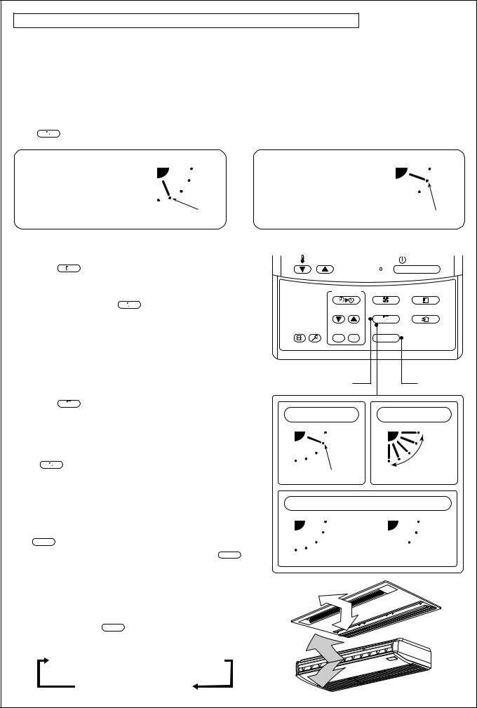
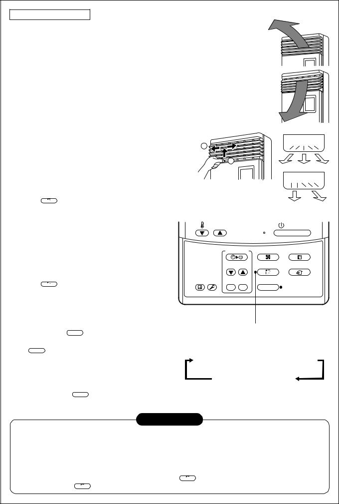
Under Ceiling Type, 1-way Air Discharge Cassette Type (2SH Series)
•While the air conditioner stops, the horizontal flap (Up/Down air direction adjustment plate) automatically directs upward.
•While the air conditioner is in ready status for heating, the horizontal flap (Up/Down air direc-
tion adjustment plate) directs upward. The swinging operation starts after heating ready status has been cleared, but “SWING  ” is displayed on the remote controller even if the status is ready to heating.
How to set up the air direction
Push |
SWING/FIX |
1 Every pushing the button, the air direction changes. |
||
button during operation. |
||||
In Heating operation |
|
In Cooling / Dry operation |
|
|
Set the horizontal flap (Up/Down |
|
Set the horizontal flap (Up/Down |
|
|
air direction adjustment plate) |
|
air direction adjustment plate) |
|
|
downward. If directing it upward, |
|
upward. If directing it downward, |
|
|
the hot air may not come to the |
Initial setup |
the dew may fall on near the air |
|
|
foot come to the foot. |
air outlet port or it drips. |
Initial setup |
||
How to start swinging
2 Push |
SWING/FIX |
button. |
Set direction of the horizontal flap (Up/Down air direction adjustment plate) to the lowest position and then push SWING/FIX button again.
•[SWING  ] is displayed and the air direction automatically changes upward/downward.
In case when one remote controller controls the multiple indoor units, each indoor unit can be selected and its air direction can be set up.
How to stop swinging
3 Push |
SWING/FIX |
button again during swinging of the |
horizontal flap.
•The horizontal flap can be stopped at the desired position. After then the air direction can be again set up from the uppermost position by pushing
SWING/FIX button.
*While the horizontal flap is set downward in cooling/drying operation, it does not stop. If stopping the horizontal flap which directs
downward during swinging, it stops after moving to the 3rd position from the top position.
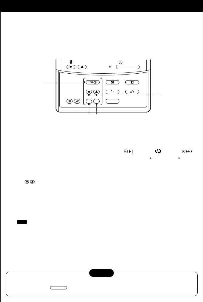
4 UNIT
• To set up the air direction individually, push UNIT button to display each indoor unit No. in a group control. Then set up the air direction to a displayed indoor unit.
•If there is no display, all the indoor units can be operated collectively.
• Every pushing UNIT button, the display exchanges as shown in the figure.
No display  Unit No. 1-1
  Unit No. 1-2
Unit No. 1-4  Unit No. 1-3
TEMP. |
|
ON / OFF |
TIMER SET |
FAN |
MODE |
TIME |
SWING/FIX |
VENT |
FILTER |
|
|
RESET TEST SET CL |
UNIT |
|
1, 2, 3 |
4 |
In FAN operation |
In all modes |
Series of operation
Initial setup
Display when stopping the swing
Fan/Heat |
Cool/Dry |
operation |
operation |
12
Right/Left air direction adjustment
To change the air outlet direction to right or left side, set the vertical flap inside of the horizontal flap to the desired direction.
INFORMATION
• If cooling operation is performed with downward discharge, dew may fall on surface of the cabinet or the horizontal flap resulted in dripping.
•If heating operation is performed with horizontal discharge, unevenness of temperature may increase in the room.
High Wall Type
Adjustment of air direction upward/downward
[In Cooling operation]
In cooling operation, use the horizontal flap with horizontal set point so that the cold air diffuses in whole room.
[In Heating operation]
In heating operation, use the horizontal flap with downward set point so that the hot air blows at the foot.
REQUIREMENT
•If cooling operation is performed with downward air outlet, dew may fall on surface of the cabinet or the horizontal flap resulted in dripping.
•If heating operation is performed with horizontal air outlet, unevenness of temperature may increase in the room.
•Do not move the horizontal flap directly with hands; otherwise a
trouble is caused. Select direction of the horizontal flap using SWING/FIX switch on the remote controller. The horizontal flap does
not stop immediately even if the switch is pushed. Adjusting the stop position, push the switch.
Adjustment of air direction rightward/leftward
To change the air outlet direction to right or left side, set the vertical flap inside of the horizontal flap to the desired direction.
Setup of air direction and swinging
1H series: Refer to description of “2-way Air Discharge Cassette Type”.
2H series: Refer to description of “Under Ceiling Type, 1-way Air Discharge Cassette Type (2SH Series)”.
13
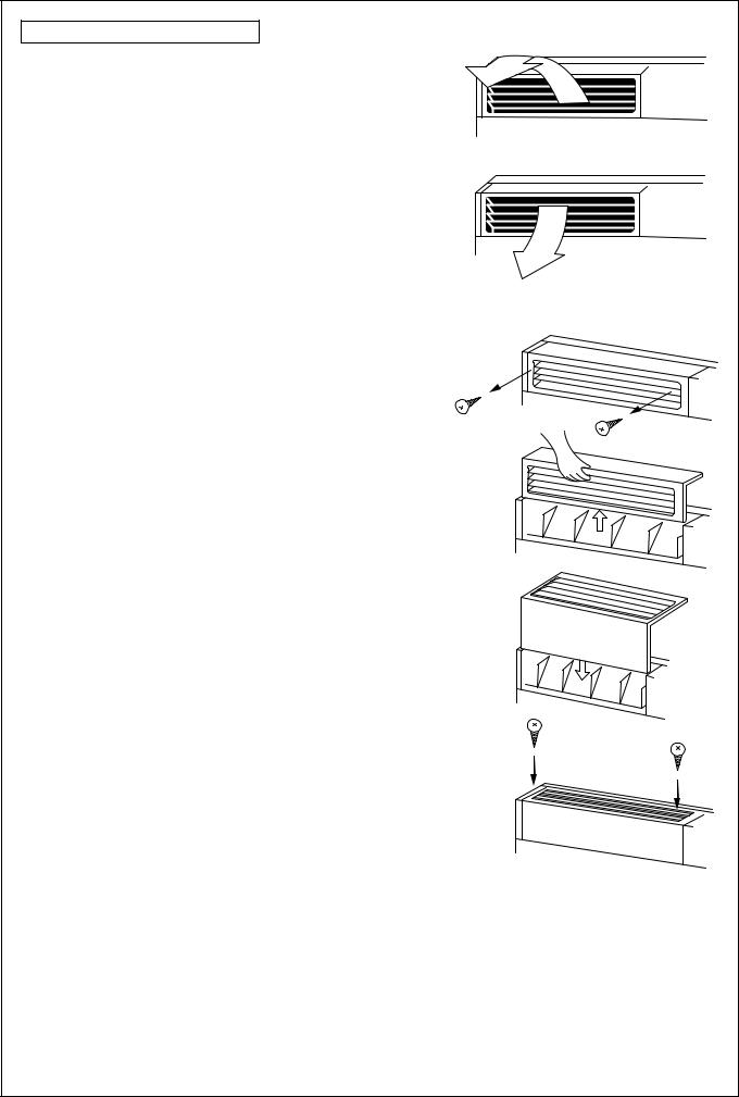
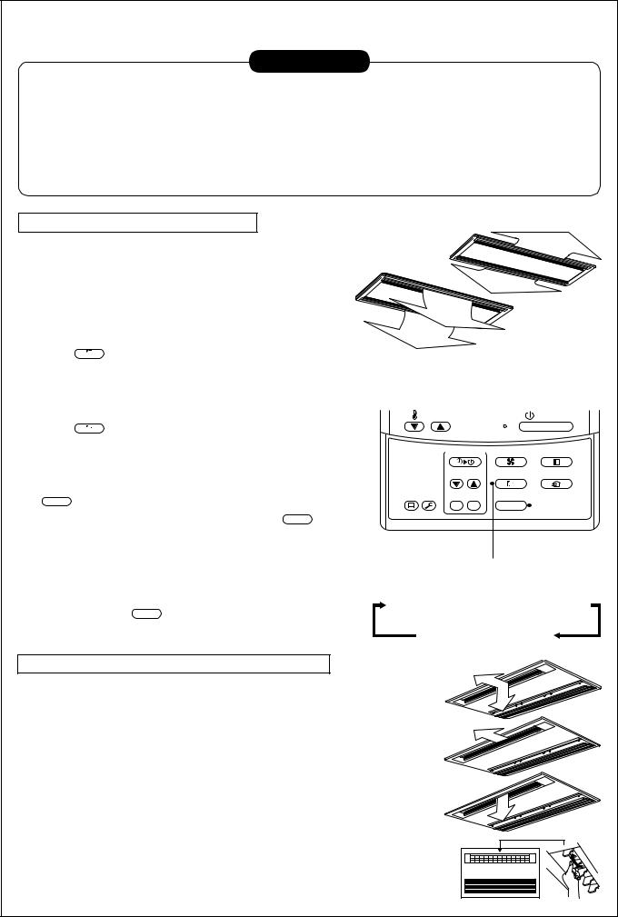
Floor Standing Cabinet Type
[In Cooling operation]
In cooling operation, use the air outlet flap with horizontal set point so that the cold air diffuses in whole room.
[In Heating operation]
In heating operation, use the air outlet flap with downward set point so that the hot air blows at the foot.
How to change the air outlet port
Change the air outlet port in the following procedure.
1 Take off two fixing screws of the air outlet port. (The fixing screws are reused.)
2 Insert the hand into the air outlet port and push up it a little, and then remove the air outlet port from the claw hook at rear side.
3 Lift up the air outlet port upward and remove it.
4 Reverse the air outlet port and attach it to the main unit.
Pay attention so that four claw hooks (two at rear and lower sides each) are hooked at mounting position.
5 Be sure to tighten the air outlet port with the removed fixing screws so that the air outlet port does not come off.
14
Floor Standing Type
Adjustment of air direction upward/downward
[In Cooling operation]
In cooling operation, move the flap with hands and use it with horizontal air outlet point so that the cold air diffuses in whole room.
[In Heating operation]
In heating operation, move the flap with hands and use the horizontal flap with downward set point so that the hot air blows at the foot.
Adjustment of air direction rightward/leftward
[In case of using unsymmetrical air directions]
Lift up the vertical flap lightly, direct it toward the desired |
2 |
direction, and lower it.
In this case, do not use the Swing function. |
1 |
|
[In case of automatic swing]
1 Push SWING/FIX button during operation.
•[SWING  ] is displayed and the air direction automatically changes rightward/ leftward.
In case when one remote controller controls the multiple indoor units, each indoor unit can be selected and its air direction can be set up.
2 Push SWING/FIX button again during swinging of the horizontal flap.
•The horizontal flap can be stopped at the desired position.
3 |
Swing button |
UNIT |
|
• To set up the air direction individually, push UNIT button to display each indoor unit No.
in a group control. Then set up the air direction to a displayed indoor unit.
•If there is no display, all the indoor units can be operated collectively.
• Every pushing UNIT button, the display exchanges as shown in the figure.
In this case, do not use the swing function.
TEMP. |
|
ON / OFF |
TIMER SET |
FAN |
MODE |
TIME |
SWING/FIX |
VENT |
FILTER |
|
|
RESET TEST SET CL |
UNIT |
|
1, 2 |
|
|
|
3 |
|
|
No display  Unit No. 1-1
  Unit No. 1-2
Unit No. 1-4  Unit No. 1-3
INFORMATION
•If cooling operation is performed with downward air outlet, dew may fall on surface of the cabinet or the horizontal flap resulted in dripping.
•If heating operation is performed with horizontal air outlet, unevenness of temperature may increase in the room.
•Do not move the flap directly with hands during swing operation; otherwise a trouble is caused. The vertical flap does not stop immediately even if the SWING/FIX button is pushed. Adjusting the stop position, push the SWING/FIX button.
15
TIMER OPERATION
A type of timer operation can be selected from the following three types.
OFF timer |
: The operation stops when the time of timer has reached the set time. |
|||
Repeat OFF timer |
: Every time, the operation stops after the set time has passed. |
|||
ON timer |
: The operation starts when the time of timer has reached the set time. |
|||
Timer operation |
|
|
|
|
|
|
TEMP. |
|
ON / OFF |
|
1 |
TIMER SET |
FAN |
MODE |
|
TIME |
SWING/FIX |
VENT |
|
|
|
|||
|
|
FILTER |
|
2 |
|
|
RESET TEST SET CL |
UNIT |
|
3 4
1 Push TIMER SET button.
•The timer display (type) changes for every push of the button.
•SET DATA and timer time displays flash.
2 Push |
TIME |
to select “SET TIME”. |
|
|
OFF |
|
|
|
|
OFF |
|
|
|
ON |
|
|
|
|
|
|
|
|
|
|
|||
|
|
|
|
|
|
|
|
|
|
|
|
(OFF timer) |
(Repeat OFF timer) |
(ON timer) |
|||||||||
|
|
|
|
No display |
|
|
|
|
|||
|
|
|
|
|
|
|
|
||||
For every push of  button, the set time increases in the unit of 0.5 hr (30 minutes). The maximum set time is 72.0 hr.
For every push of  button, the set time decreases in the unit of 0.5 hr (30 minutes). The minimum set time is 0.5 hr.
3 Push SET button.
•SETTING display disappears and timer time display goes on.
(When ON timer is activated, timer time, ON timer are displayed and other displays disappear.)
Cancel of timer operation
4 Push CL button.
• TIMER display disappears.
NOTICE
• When the operation stops after the timer reached the preset time, the Repeat OFF timer resumes the operation by pushing  ON / OFF button and stops the operation after the time of the timer has reached the set time.
16
INSTALLATION
Installation location
 WARNING
•Select a location for installation that will be able to safely bear the weight of the unit.
If the installation location is not strong enough to support the unit and the unit falls, injury could result.
CAUTION
•Do not install the unit in a location where combustible gases could conceivably leak.
Leaking gases that accumulate in the vicinity of the unit could be ignited by the unit.
REQUIREMENT
•A location that permits level installation of the unit
•A location that provides enough space to service the unit safely
•A location where water draining from the unit will not pose a problem
Avoid the following types of locations :
•Locations where salt is present in large amounts (seaside areas), or where sulfuric gases are present in large amounts (hot springs areas)
(If the unit is to be used in such areas, special maintenance is necessary.)
•Locations that generate oils (including machine oils), steam, oily smoke, or corrosive gases
•Locations where organic solvents are used
•Locations in the vicinity of equipment that generates high frequency signals
•Locations where the outdoor unit will blow in the direction of a neighbor's window
•Locations where the noise of the outdoor unit will pose a problem
•Locations with poor air circulation
Electric wiring
 WARNING
Check that earthing practice is correctly performed.
Grounding is necessary. If earthing practice is incomplete, an electric shock may be caused.
CAUTION
Check the circuit breaker is fitted.
Attaching the earth leakage breaker is necessary. Otherwise, an electric shock may be caused.
Make sure that correct capacity Fuses are used.
Using wire or copper wire may cause a fire or trouble.
For the power supply, use a circuit with rated voltage exclusive for air conditioner.
To disconnect the appliance from the main power supply.
This appliance must be connected to the main power supply by means of circuit breaker or a switch with a contact separation of at least 3mm.
17
MAINTENANCE
Cleaning of air filter
•When [FILTER] is displayed on the remote controller, maintain the air filter.
•Clogging of air filter decreases cooling/heating effect.
FILTER display
Notifies the time to clean the air filter.
FILTER reset
Push the FILTER switch after cleaning. “FILTER” display disappears.
|
|
|
CODE No. |
SET DATA SETTING TEST |
|
|
|
|
UNIT No. |
|
|
H |
R.C. |
No. |
|
|
|
|
|
TEMP. |
|
|
ON / OFF |
|
TIMER SET |
FAN |
MODE |
|
TIME |
SWING/FIX |
VENT |
FILTER |
|
|
|
RESET TEST |
SET CL |
UNIT |
|
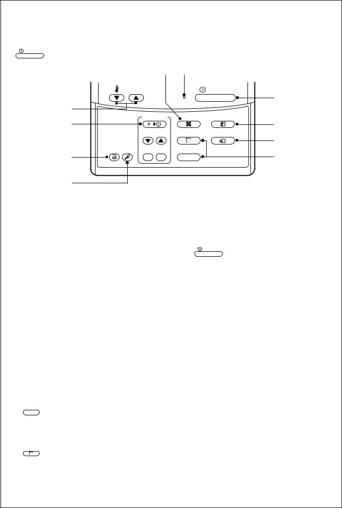
WARNING
Be sure to turn off the main power switch prior to the maintenance.
•Please do not intend to do the daily maintenance and/or Air Filter cleaning by yourself.
Cleaning of the air filter and other parts of the air filter involves dangerous work in high places, so be sure to have a service person do it. Do not attempt it yourself.
<Daily maintenance>
•For daily maintenance including Air Filter cleaning, make sure to ask the qualified service person particularly following models;
4-way Air Discharge Cassette Type |
Concealed Duct Type |
Under Ceiling Type |
2-way Air Discharge Cassette Type |
Slim Duct Type |
|
1-way Air Discharge Cassette Type |
Concealed Duct, High Static Pressure Type |
|
NO GOOD |
|
NO GOOD |
|
|
|
NO GOOD
2-way Air Discharge |
4-way Air Discharge |
1-way Air Discharge |
Cassette Type |
Cassette Type |
Cassette Type |
|
NO GOOD |
NO GOOD |
|
|
NO GOOD |
NO GOOD |
Concealed Duct Type Under Ceiling Type |
Slim Duct Type Concealed Duct, |
|
High Static Pressure Type |
18
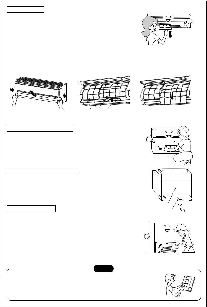
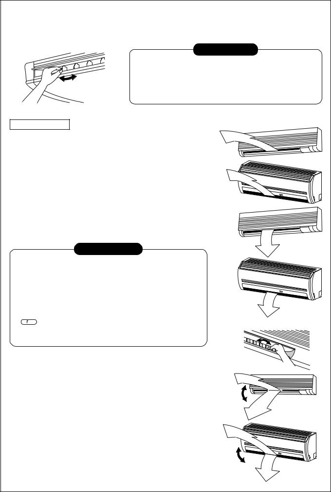
High Wall Type
(Model : 1H series)
•Push the projection at the center of air filter. Clip is out.
•Undo the clip of air filter, pull the air filter downward while pushing it toward the main unit side.
(Model : 2H series)
•Open the air inlet grille.
Lift the air inlet grille up to the horizontal position.
•Take hold of the left and right handles of the air filter and lift it up slightly, then pull downward to take it out from the filter holder.
Filter holder
Push the air filter, and pull it downward.
Floor Standing Cabinet Type
•Push down the upper part of the suction port a little, and then pull toward you to remove it.
•Take out the air filter inside of the suction port.
Floor Standing Concealed Type
•Push down hook of the air filter on the front panel (Lower side).
•Pull the air filter toward you to remove it.
Floor Standing Type
Removal / Attachment of air filter
•Pull the air filter toward you.
•To attach the air filter, insert it into the main body and push in it.
NOTE
Front panel (Lower)
Air filter knob
•For cleaning of air filter, use a cleaner or brush clean. If stain is heavy,
it is effective to wash the air filter in tepid water mixed with neutral detergent.
•After washing, rinse it well, and dry it in the shade.
•Install again the air filter which has been cleaned.
19

Return the air filter
•Insert the upper portion of air filter confirming to fit it is right and left edges on the indoor unit until it is firmly set.
•Close the air inlet grille.
If the FILTER lamp on the indoor unit is indicated, press the FILTER button on the remote controller or the TEMPORARY button on the indoor unit to turn off the lamp.
Filter holder
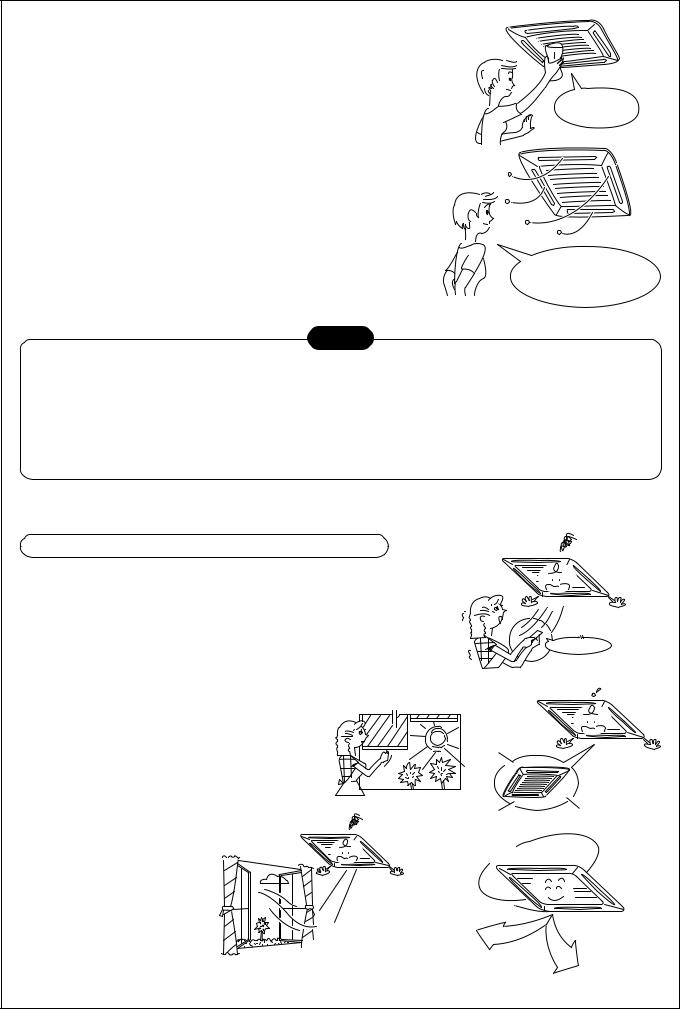
Cleaning the air inlet grille
1.Remove the air inlet grille.
Hold the two sides of the air inlet grille and open upwards.
Move the center arm to the left and remove the grille.
2. Wash it with water using a soft sponge or towel.
(Do not use metallic scrubbing brush or other hard brushes.)
•Use of such hard objects will cause scratches on the surface of the grille, and the metal coating to peel off.
•If very dirty, clean the air inlet grille with a neutral detergent for kitchen use, and rinse it off with water.
3.Wipe out water from the air inlet grille and dry it.
4. Fit the left and right arms of the air inlet grille to the shafts on the two sides of the air conditioner and push in completely, and then push in the center arm.
5.Check that the center arm has been completely inserted and close the air inlet grille.
• Push the arrow locations (Four) at the bottom of the air inlet grille to check whether the grill is completely closed.
Cleaning of main unit / remote controller
CAUTION
•Wipe them with soft and dry cloth.
•A cloth dampened with cold water may be used on the indoor unit if it is very dirty.
•Never use a damp cloth on the main unit and remote controller.
•Do not use a chemically-treated duster for wiping or leave such materials on the unit for long. It may damage or fade the surface of the unit.
•Do not use benzine, thinner, polishing powder, or similar solvents for cleaning. These may cause the plastic surface to crack or deform.
Thinner
Polishing Benzene powder
Chemical floor-cloth
Do not use.
20
If you do not plan to use the unit for more than 1 month
1. Operate the fan for 3 to 4 hours to dry inside the unit
•Operate “FAN” mode.
2.Stop the air conditioner and turn off the main power switch
or the circuit breaker. |
I will wipe soft |
|
and dry cloth! |
Checks before operation
1. Check that the air filters are installed.
2. Check that the air outlet or inlet is not blocked.
3.Turn on the main power switch or the circuit breaker for the main power supply to the air conditioner.
Use after drying when it has not been used for a long time!
NOTE
For Air conditioning system which is operated regularly, cleaning and maintenance of the indoor/outdoor units are strongly recommended.
As a general rule, if an indoor unit is operated for about 8 hours daily, the indoor/outdoor units will need to be cleaned at least once every 3-MONTH. This cleaning and maintenance shall be carried out by a qualified person.
Failure to clean the indoor/outdoor units regularly will result in poor performance, icing, water leaking and even compressor failure.
HINTS FOR ECONOMICAL OPERATION
Maintain room temperature at comfortable level Clean air filters
The clogged air filter impairs the performance of the air conditioner.
Never open doors and windows more often than necessary
To keep cool or warm air in the room, never open doors and windows more often than necessary.
Window curtains
Gee, chilly
Control
In cooling, close the curtains to avoid direct sunlight.
In heating, close the curtains to keep the heat in.
Get uniform circulation of room air
Adjust the air flow direction for the even circulation of room air.
Please |
close |
|
Clean, please.
Blows upward
Air flow adjustment
Cool and dry air
Warm
air
Blows downward
21
AIR CONDITIONER OPERATIONS AND PERFORMANCE
Check before operation
•Check whether earth wire is disconnected or out of place.
•Check that air filter is installed to the indoor unit.
Heating capacity
WARNING
Turn on the power switch 12 hours or more before starting before operation.
•For heating, a heat pump system which sucks in outside heat air and discharges it into the room is adopted.
If temperature of the outside air lowers, the heating capacity decreases.
•When temperature of the outside air is low, it is recommended to use other heating equipment together.
Defrost operation during heating operation
•If the outdoor unit has some frost during heating operation, the operation mode changes automatically to defrost mode to increase the heating effect (for approx. 2 to 10 minutes).
•During defrost operation, fans of the indoor and the outdoor units stop.
Protection for 3 minutes
•The outdoor unit does not operate for approx. 3 minutes after air conditioner has been immediately restarted after stop, or power switch has been turned on. This is to protect the system.
Main power failure
•If a power failure occurred during the operation, all operations stop.
•When restarting the operation, push ON/OFF button again.
Fan rotation of stopped unit
•While other indoor units operate, the fan on indoor units on “stand-by” rotates to protect the machine once per approx. 1 hour for several minutes.
Protective device (High pressure switch)
The high pressure switch stops the air conditioner automatically when excessive load is applied to the air conditioner.
If the protective device works, the operation lamp keeps lit but the operation stops.
When the protective device works, check characters “ ” in the remote controller display part flash. The protective device may work in the following cases.
•When suction or discharge port of the outdoor unit closed.
•When strong wind blows continuously against discharge port of the outdoor unit.
•When dust or dirt is excessively adhered to air filter of the indoor unit.
•When discharge port of the indoor unit is blocked.
Cooling/heating operation of Heat Recovery Multi air conditioner
•When the outdoor temperature goes out of the operable range, cooling or heating operation may not be performed in order to protect the equipment. In this case, “ ” goes on.
Characteristics of heating operation
•Hot air is not out immediately after the operation has started. After 3 to 5 minutes (differs according to room or outside temperature) has passed and the indoor heat exchanger has been warmed up, hot air blows out.
•During operation, the outdoor unit may stop if outside temperature becomes high.
•When other outdoor unit performs heating operation while the fan is operating, the fan operation may be stopped temporarily to prevent blowing of hot air.
Characteristics of cooling/heating simultaneous operation
• If the outdoor temperature drops during operation, the fan of the outdoor unit may stop.
22
Air conditioner operating conditions
For proper performance, operate the air conditioner under the following temperature conditions:
Cooling |
Outdoor temperature |
: –10°C to 43°C (Dry-bulb temp.) |
||
operation |
|
|
|
|
Room temperature |
: 21°C to 32°C (Dry-bulb temp.), 15°C to 24°C (Wet-bulb temp.) |
|||
|
||||
|
|
|
||
|
CAUTION |
Room relative humidity – less than 80 %. If the air conditioner operates |
||
|
|
in excess of this figure, the surface of the air conditioner may cause dewing. |
||
Heating |
Outdoor temperature |
: –15°C to 21°C (Dry-bulb temp.), –15°C to 15.5°C (Wet-bulb temp.) |
||
operation |
|
|
|
|
Room temperature |
: 15°C to 28°C (Dry-bulb temp.) |
|||
|
||||
|
|
|
|
|
• If air conditioner is used outside of the above conditions, safety protection may work.
*Do not use “Super HRM” for other than personal usage where the ambient temperature may go down below –5°C. (For example, OA equipment/Electric device/Food/Animals and plants/Art object)
CAUTION
When outdoor temperature goes out of specified range, “
 or
or  ” mark is indicated on the Wired remote controller display and required operation will stop.
“
 &
&  ” : When heating operation. “ ” : When cooling operation.
Notice :
•This indication is not failure.
•When outdoor temperature goes back to specified range, “ or
or  ” disappear and start normal operation.
•Operation stops because concurrent operation can not be kept in the condition of out of specification for Super HRM.
(Outdoor temp. (DB) < –10°C : Cooling, > 21°C : Heating)
RE-INSTALLATION
DANGER
Ask the dealer or an installation professional to re-install the air conditioner to a new place or move it to another place and to observe the following items.
If the air conditioner is inappropriate installed by yourself, it may cause electric shock or fire.
Do not install the air conditioner in the following places
•Do not install the air conditioner in any place within 1 m from a TV, stereo, or radio set. If the unit is installed in such place, noise transmitted from the air conditioner affects the operation of these appliances.
•Do not install the air conditioner near a high frequency appliance (sewing machine or massager for business use, etc.), otherwise the air conditioner may malfunction.
•Do not install the air conditioner in a humid or oily place, or in a place where steam, soot, or corrosive gas is generated.
•Do not install the air conditioner in a salty place such as seaside area.
•Do not install the air conditioner in a place where a great deal of machine oil is used.
•Do not install the air conditioner in a place where it is usually exposed to strong wind such as in seaside area or on the roof or upper floor of a building.
•Do not install the air conditioner in a place where sulfureous gas generated such as in a spa.
•Do not install the air conditioner in a vessel or mobile crane.
Be careful with noise or vibrations
• Do not install the air conditioner in a place where noise by outdoor unit or hot air from its air outlet annoys your neighbors.
• Install the air conditioner on a solid and stable foundation so that it prevents transmission of resonating, operation noise and vibration.
• If one indoor unit is operating, some sound may be audible from other indoor units that are not operating.
23

WHEN THE FOLLOWING SYMPTOMS ARE FOUND
Check the points described below before asking repair servicing.
It is not a failure.
Check again.
Symptom
Outdoor unit |
• |
White misty cold air or |
|
|
water is out. |
|
• |
Sometimes, noise |
|
|
“Pushu !” is heard. |
Indoor unit |
• |
“Swish” sound is |
|
|
heard sometimes. |
•Slight “Pishi!” sound is heard.
•Discharge air smells.
•“ ” indication is lit.
•Sound or cool air is output from the stand by indoor unit.
•When power of the air conditioner is turned on, “Ticktock” sound is heard.
Operates or stops automatically.
Does not operate.
Silent
Cause
•Fan of the outdoor unit stops automatically and performs defrost operation.
•Solenoid valve works when defrost operation starts or finishes.
•When the operation has started, during the operation, or immediately after the operation has stopped, a sound such as water flows may be heard, and the operation sound may become larger for 2 or 3 minutes immediately after the operation has started. They are flowing sound of refrigerant or draining sound of dehumidifier.
•This is sound generated when heat exchanger, etc. expand and contract slightly due to change of temperature.
•Various smell such as one of wall, carpet, clothes, cigarette, or cosmetics adhere to the air conditioner.
•Do not the outdoor temperature go out of the specified range?
•When the manager of the air conditioner has fixed the operation to COOL or HEAT, and an operation contrary to the setup operation is performed.
•When fan operation stopped to prevent discharge of hot air.
•Since refrigerant is flowed temporarily to prevent stay of oil or refrigerant in the stand by indoor unit, sound of flowing refrigerant, “Kyururu” or “Shaa” may be heard or white steam when other indoor unit operates in HEAT mode, and cold air in COOL mode may be blow-out.
•Sound is generated when the expansion valve operates when power has been turned on.
•Is the timer “ON” or “OFF”?
•Is it a power failure?
•Is the power switch turned off?
•Is the power fuse or breaker blown?
•Has the protective device operated? (The operation lamp goes on.)
•Is the timer “ON”? (The operation lamp goes on.)
•Do not the outdoor temperature go out of the specified range?
Air is not cooled or warmed sufficiently.
It’s strange.
•Is the suction port or discharge port of the outdoor unit obstructed?
•Are any door or window open?
•Is the air filter clogged with dust?
•Is discharge louver of the indoor unit set at appropriate position?
•Is air selection set to “LOW” “MED”, and is the operation mode set to “FAN”?
•Is the setup temp. the appropriate temperature?
•Do not the outdoor temperature go out of the specified range?
When the following symptoms are found, stop the operation immediately, turn off the power switch, and contact the dealer which you have purchased the air conditioner.
•Activation of switch is unstable.
•The main power fuse often blows out, or circuit breaker is often activated.
•Foreign matters or water entered by mistake.
•When if activation cause of the protective device has been removed, the operation is not performed.
•Other unusual status occurred.
24
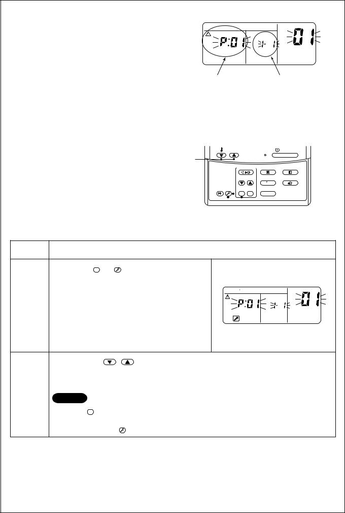
Confirmation and check
When a trouble occurred in the air conditioner, the check code and the indoor unit No. appear on the display part of the remote controller.
The check code is only displayed during the operation.
If the display disappears, operate the air conditioner according to the following “Confirmation of error history” for confirmation.
Confirmation of error history
When a trouble occurred on the air conditioner, the trouble history can be confirmed with the following procedure. (The trouble history is stored in memory up to 4 troubles.)
The history can be confirmed from both operating status and stop status.
|
CODE No. |
UNIT |
No. |
R.C. |
No. |
Check code |
Indoor unit No. in which |
|
an error occurred |
TEMP. |
|
ON / OFF |
2 |
|
|
TIMER SET |
FAN |
MODE |
TIME |
SWING/FIX |
VENT |
FILTER |
|
|
RESET TEST SET CL |
UNIT |
|
3 

 1
1
Procedure |
Description |
When pushing SET and TEST buttons at the same time for 4 seconds or more, the following display appears.
If [Service check] is displayed, the mode enters in the
CODE No.
trouble history mode.
1 |
|
UNIT |
No. |
• |
[01 : Order of trouble history] is displayed in CODE No. |
|
|
|
R.C. |
No. |
|
|
|
window. |
|
•[Check code] is displayed in CHECK window.
•[Indoor unit address in which an error occurred] is displayed in UNIT No.
|
Every pushing of [ |
, |
] button used to set temperature, the trouble history stored in memory is |
|
displayed in order. |
|
|
2 |
The numbers in CODE No. indicate CODE No. [01] (latest) → [04] (oldest). |
||
|
|
|
|
|
CAUTION |
|
|
|
Do not push CL button because all the trouble history of the indoor unit will be deleted. |
||
|
|
||
3 |
After confirmation, push TEST button to return to the usual display. |
||
|
|
|
|
1.Check the troubles according to the above procedure.
2.Ask an authorized dealer or qualified service (maintenance) professional to repair or maintain the air conditioner.
3.More details of the service code are explained in Service Manual.
25
 Loading...