


FILE NO. A11-016
SERVICE MANUAL
(SPLIT TYPE)
OUTDOOR UNIT
< DIGITAL INVERTER>
RAV-SM1103AT-E1
RAV-SM1403AT-E1
R410A
PRINTED IN JAPAN, Jan., 2012 ToMo
|
|
CONTENTS |
|
Precaution for Safety ............................................................................................................ |
6 |
||
New Refrigerant (R410A) .................................................................................................... |
11 |
||
1. |
SPECIFICATIONS ........................................................................................................ |
13 |
|
|
1-1. |
Outdoor Unit ............................................................................................................................... |
13 |
|
1-2. |
Characteristic Curve ................................................................................................................. |
14 |
2. |
CONSTRUCTION VIEWS (EXTERNAL VIEWS) .......................................................... |
15 |
|
3. |
REFRIGERATING CYCLE DIAGRAM ......................................................................... |
17 |
|
4. |
WIRING DIAGRAM ...................................................................................................... |
19 |
|
5. |
SPECIFICATIONS OF ELECTRICAL PARTS .............................................................. |
20 |
|
6. |
REFRIGERANT R410A ................................................................................................ |
21 |
|
|
6-1. |
Safety During Installation/Servicing ........................................................................................ |
21 |
|
6-2. |
Refrigerant Piping Installation ............................................................................................... |
21 |
|
6-3. |
Tools............................................................................................................................................ |
25 |
|
6-4. |
Recharging of Refrigerant ........................................................................................................ |
25 |
|
6-5. |
Brazing of Pipes ......................................................................................................................... |
26 |
|
6-6. |
Instructions for Re-use Piping of R22 or R407C .................................................................... |
28 |
7. |
CIRCUIT CONFIGURATION AND CONTROL SPECIFICATIONS .............................. |
31 |
|
|
7-1. |
Outdoor Unit Control ................................................................................................................. |
31 |
|
7-2. |
Outline of Main Controls ........................................................................................................... |
32 |
8. |
TROUBLESHOOTING.................................................................................................. |
37 |
|
|
8-1. |
Summary of Troubleshooting ................................................................................................... |
37 |
|
8-2. |
Troubleshooting ......................................................................................................................... |
39 |
9. |
SETUP AT LOCAL SITE AND OTHERS...................................................................... |
63 |
|
|
9-1. |
Calling of Error History ............................................................................................................. |
63 |
|
9-2. |
Group Control Operation .......................................................................................................... |
63 |
|
9-3. |
Outdoor Unit ............................................................................................................................... |
65 |
|
9-4. |
Applicable Control of Outdoor Unit ......................................................................................... |
72 |
10. |
ADDRESS SETUP ....................................................................................................... |
73 |
|
|
10-1. |
Address Setup Procedure ......................................................................................................... |
73 |
|
10-2. |
Address Setup & Group Control .............................................................................................. |
74 |
|
10-3. |
Remote Controller Wiring.......................................................................................................... |
77 |
|
10-4. |
Address Setup (Manual setting from remote controller) ....................................................... |
77 |
|
10-5. |
Confirmation of Indoor Unit No. Position ................................................................................ |
78 |
11. |
REPLACEMENT OF THE SERVICE P.C. BOARD MCC-1630 ..................................... |
80 |
|
12. |
HOW TO EXCHANGE COMPRESSOR........................................................................ |
81 |
|
|
12-1. |
Exchanging Procedure of Compressor (Outline) ................................................................... |
81 |
|
12-2. |
Exchange of Compressor ......................................................................................................... |
81 |
13. |
DETACHMENTS ........................................................................................................... |
82 |
|
14. |
EXPLODED VIEWS AND PARTS LIST........................................................................ |
90 |
|
– 2 –
Original instruction
Please read carefully through these instructions that contain important information which complies with the “Machinery” Directive (Directive 2006/42/EC), and ensure that you understand them.
Generic Denomination: Air Conditioner
Definition of Qualified Installer or Qualified Service Person
The air conditioner must be installed, maintained, repaired and removed by a qualified installer or qualified service person.
When any of these jobs is to be done, ask a qualified installer or qualified service person to do them for you.
A qualified installer or qualified service person is an agent who has the qualifications and knowledge described in the table below.
Agent |
|
Qualifications and knowledge which the agent must have |
|
|
|
Qualified |
• |
The qualified installer is a person who installs, maintains, relocates and removes the air |
installer ( 1) |
|
conditioners made by Toshiba Carrier Corporation. |
|
|
He or she has been trained to install, maintain, relocate and remove the air conditioners made by |
|
|
Toshiba Carrier Corporation or, alternatively, he or she has been instructed in such operations by |
|
|
an individual or individuals who have been trained and is thus thoroughly acquainted with the |
|
|
knowledge related to these operations. |
|
• |
The qualified installer who is allowed to do the electrical work involved in installation, relocation |
|
|
and removal has the qualifications pertaining to this electrical work as stipulated by the local laws |
|
|
and regulations, and he or she is a person who has been trained in matters relating to electrical |
|
|
work on the air conditioners made by Toshiba Carrier Corporation or, alternatively, he or she has |
|
|
been instructed in such matters by an individual or individuals who have been trained and is thus |
|
|
thoroughly acquainted with the knowledge related to this work. |
|
• |
The qualified installer who is allowed to do the refrigerant handling and piping work involved in |
|
|
installation, relocation and removal has the qualifications pertaining to this refrigerant handling |
|
|
and piping work as stipulated by the local laws and regulations, and he or she is a person who |
|
|
has been trained in matters relating to refrigerant handling and piping work on the air conditioners |
|
|
made by Toshiba Carrier Corporation or, alternatively, he or she has been instructed in such |
|
|
matters by an individual or individuals who have been trained and is thus thoroughly acquainted |
|
|
with the knowledge related to this work. |
|
• |
The qualified installer who is allowed to work at heights has been trained in matters relating to |
|
|
working at heights with the air conditioners made by Toshiba Carrier Corporation or, alternatively, |
|
|
he or she has been instructed in such matters by an individual or individuals who have been |
|
|
trained and is thus thoroughly acquainted with the knowledge related to this work. |
|
|
|
Qualified service |
• |
The qualified service person is a person who installs, repairs, maintains, relocates and removes |
person ( 1) |
|
the air conditioners made by Toshiba Carrier Corporation. He or she has been trained to install, |
|
|
repair, maintain, relocate and remove the air conditioners made by Toshiba Carrier Corporation or, |
|
|
alternatively, he or she has been instructed in such operations by an individual or individuals who |
|
|
have been trained and is thus thoroughly acquainted with the knowledge related to these operations. |
|
• |
The qualified service person who is allowed to do the electrical work involved in installation, |
|
|
repair, relocation and removal has the qualifications pertaining to this electrical work as stipulated |
|
|
by the local laws and regulations, and he or she is a person who has been trained in matters |
|
|
relating to electrical work on the air conditioners made by Toshiba Carrier Corporation or, |
|
|
alternatively, he or she has been instructed in such matters by an individual or individuals who |
|
|
have been trained and is thus thoroughly acquainted with the knowledge related to this work. |
|
• |
The qualified service person who is allowed to do the refrigerant handling and piping work |
|
|
involved in installation, repair, relocation and removal has the qualifications pertaining to this |
|
|
refrigerant handling and piping work as stipulated by the local laws and regulations, and he or |
|
|
she is a person who has been trained in matters relating to refrigerant handling and piping |
|
|
work on the air conditioners made by Toshiba Carrier Corporation or, alternatively, he or she |
|
|
has been instructed in such matters by an individual or individuals who have been trained |
|
|
and is thus thoroughly acquainted with the knowledge related to this work. |
|
• |
The qualified service person who is allowed to work at heights has been trained in matters |
|
|
relating to working at heights with the air conditioners made by Toshiba Carrier Corporation or, |
|
|
alternatively, he or she has been instructed in such matters by an individual or individuals who |
|
|
have been trained and is thus thoroughly acquainted with the knowledge related to this work. |
|
|
|
|
|
– 3 – |
Definition of Protective Gear
When the air conditioner is to be transported, installed, maintained, repaired or removed, wear protective gloves and ‘safety’ work clothing.
In addition to such normal protective gear, wear the protective gear described below when undertaking the special work detailed in the table below.
Failure to wear the proper protective gear is dangerous because you will be more susceptible to injury, burns, electric shocks and other injuries.
Work undertaken |
Protective gear worn |
|
|
|
|
All types of work |
Protective gloves |
|
“Safety” working clothing |
||
|
||
|
|
|
|
Gloves to provide protection for electricians and from heat |
|
Electrical-related work |
Insulating shoes |
|
|
Clothing to provide protection from electric shock |
|
|
|
|
Work done at heights (50 cm or more) |
Helmets for use in industry |
|
|
|
|
Transportation of heavy objects |
Shoes with additional protective toe cap |
|
|
|
|
Repair of outdoor unit |
Gloves to provide protection for electricians and from heat |
|
|
|
The important contents concerned to the safety are described on the product itself and on this Service Manual.
Please read this Service Manual after understanding the described items thoroughly in the following contents (Indications/Illustrated marks), and keep them.
[Explanation of indications]
Indication |
Explanation |
|
|
DANGER |
Indicates contents assumed that an imminent danger causing a death or serious injury of |
the repair engineers and the third parties when an incorrect work has been executed. |
Indicates possibilities assumed that a danger causing a death or serious injury of the WARNING repair engineers, the third parties, and the users due to troubles of the product after work
when an incorrect work has been executed.
Indicates contents assumed that an injury or property damage ( ) may be caused on the CAUTION repair engineers, the third parties, and the users due to troubles of the product after work
when an incorrect work has been executed.
Property damage : Enlarged damage concerned to property, furniture, and domestic animal/pet
[Explanation of illustrated marks]
Mark |
Explanation |
Indicates prohibited items (Forbidden items to do)
The sentences near an illustrated mark describe the concrete prohibited contents.
Indicates mandatory items (Compulsory items to do)
The sentences near an illustrated mark describe the concrete mandatory contents.
Indicates cautions (Including danger/warning)
The sentences or illustration near or in an illustrated mark describe the concrete cautious contents.
– 4 –
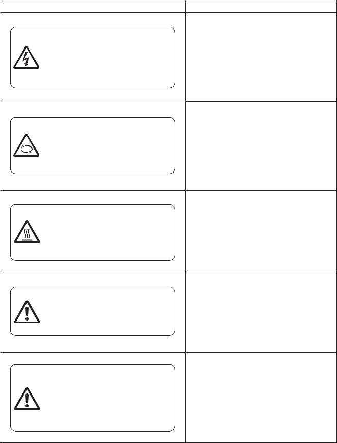
Warning Indications on the Air Conditioner Unit
[Confirmation of warning label on the main unit]
Confirm that labels are indicated on the specified positions
If removing the label during parts replace, stick it as the original.
Warning indication |
Description |
WARNING |
WARNING |
|
|
ELECTRICAL SHOCK HAZARD |
|
ELECTRICAL SHOCK HAZARD |
||
Disconnect all remote electric power supplies |
||
Disconnect all remote electric |
||
before servicing. |
||
power supplies before servicing. |
|
|
|
|
WARNING |
WARNING |
|
|
Moving parts. |
|
Moving parts. |
||
Do not operate unit with grille removed. |
||
Do not operate unit with grille removed. |
||
Stop the unit before the servicing. |
||
Stop the unit before the servicing. |
||
|
||
|
|
CAUTION |
CAUTION |
|
|
|
High temperature parts. |
High temperature parts. |
|
You might get burned when removing |
You might get burned when removing this panel. |
this panel. |
|
|
|
CAUTION |
CAUTION |
|
|
Do not touch the aluminum fins of the unit. |
|
Do not touch the aluminum fins of the unit. |
||
Doing so may result in injury. |
||
Doing so may result in injury. |
||
|
||
|
|
CAUTION |
CAUTION |
|
|
||
BURST HAZARD |
BURST HAZARD |
|
Open the service valves before the |
Open the service valves before the operation, |
|
otherwise there might be the burst. |
||
operation, otherwise there might be the |
||
|
||
burst. |
|
|
|
|
– 5 –

Precaution for Safety
The manufacturer shall not assume any liability for the damage caused by not observing the description of this manual.
 DANGER
|
Before carrying out the installation, maintenance, repair or removal work, be sure to set the circuit |
|
|
breaker to the OFF position. Otherwise, electric shocks may result. |
|
|
|
|
|
Before opening the intake grille of the indoor unit or service panel of the outdoor unit, set the circuit |
|
|
breaker to the OFF position. Failure to set the circuit breaker to the OFF position may result in electric |
|
|
shocks through contact with the interior parts. Only a qualified installer (*1) or qualified service person |
|
|
(*1) is allowed to remove the intake grille of the indoor unit or service panel of the outdoor unit and do |
|
|
the work required. |
|
Turn off |
|
|
Before starting to repair the outdoor unit fan or fan guard, be absolutely sure to set the circuit breaker |
||
breaker. |
to the OFF position, and place a “Work in progress” sign on the circuit breaker before proceeding with |
|
|
the work. |
|
|
|
|
|
When cleaning the filter or other parts of the indoor unit, set the circuit breaker to OFF without fail, and |
|
|
place a “Work in progress” sign near the circuit breaker before proceeding with the work. |
|
|
|
|
|
When you access inside of the service panel to repair electric parts, wait for about five minutes after |
|
|
turning off the breaker. Do not start repairing immediately. Otherwise you may get electric shock by |
|
|
touching terminals of high-voltage capacitors. Natural discharge of the capacitor takes about five |
|
|
minutes. |
|
|
|
|
Electric shock |
Before operating the air conditioner after having completed the work, check that the electrical parts |
|
box cover of the indoor unit and service panel of the outdoor unit are closed, and set the circuit |
||
hazard |
||
breaker to the ON position. You may receive an electric shock etc. if the power is turned on without first |
||
|
||
|
conducting these checks. |
|
|
|
|
|
Even if the circuit breaker has been set to the OFF position before the service panel is removed and |
|
|
the electrical parts are repaired, you will still risk receiving an electric shock. |
|
Execute |
For this reason, short-circuit the high-voltage capacitor terminals to discharge the voltage before |
|
proceeding with the repair work. For details on the short-circuiting procedure, refer to the Service |
||
discharge |
Manual. You may receive an electric shock if the voltage stored in the capacitors has not been |
|
between |
sufficiently discharged. |
|
terminals. |
|
|
|
Place a “Work in progress” sign near the circuit breaker while the installation, maintenance, repair or |
|
|
removal work is being carried out. There is a danger of electric shocks if the circuit breaker is set to |
|
|
ON by mistake. |
|
|
|
|
Prohibition |
When checking the electric parts, removing the cover of the electric parts box of Indoor Unit and/or |
|
front panel of Outdoor Unit inevitably to determine the failure, put a sign “Do not enter” around the site |
||
|
before the work. Failure to do this may result in third person getting electric shock. |
|
|
|
|
|
If, in the course of carrying out repairs, it becomes absolutely necessary to check out the electrical |
|
|
parts with the electrical parts box cover of one or more of the indoor units and the service panel of the |
|
|
outdoor unit removed in order to find out exactly where the trouble lies, wear insulated heat-resistant |
|
Stay on |
gloves, insulated boots and insulated work overalls, and take care to avoid touching any live parts. |
|
You may receive an electric shock if you fail to heed this warning. Only qualified service person (*1) is |
||
protection |
||
allowed to do this kind of work. |
||
|
||
|
|
 WARNING
|
Before starting to repair the air conditioner, read carefully through the Service Manual, and repair the |
|
|
air conditioner by following its instructions. |
|
|
|
|
|
Only qualified service person (*1) is allowed to repair the air conditioner. Repair of the air conditioner |
|
|
by unqualified person may give rise to a fire, electric shocks, injury, water leaks and/or other problems. |
|
|
|
|
|
Only a qualified installer (*1) or qualified service person (*1) is allowed to carry out the electrical work |
|
|
of the air conditioner. Under no circumstances must this work be done by an unqualified individual |
|
|
since failure to carry out the work properly may result in electric shocks and/or electrical leaks. |
|
General |
|
|
Wear protective gloves and safety work clothing during installation, servicing and removal. |
||
|
||
|
|
|
|
Use wiring that meets the specifications in the Installation Manual and the stipulations in the local |
|
|
regulations and laws. Use of wiring which does not meet the specifications may give rise to electric |
|
|
shocks, electrical leakage, smoking and/or a fire. |
|
|
|
– 6 –

 WARNING
|
The appliance shall be installed in accordance with national wiring regulations. Capacity shortages of |
|
|
the power circuit or an incomplete installation may cause an electric shock or fire. |
|
|
|
|
|
Only a qualified installer (*1) or qualified service person (*1) is allowed to undertake work at heights |
|
|
using a stand of 50 cm or more or to remove the intake grille of the indoor unit to undertake work. |
|
|
|
|
|
When working at heights, use a ladder which complies with the ISO 14122 standard, and follow the |
|
|
procedure in the ladder’s instructions. Also wear a helmet for use in industry as protective gear to |
|
|
undertake the work. |
|
|
|
|
|
When working at heights, put a sign in place so that no-one will approach the work location, before |
|
|
proceeding with the work. Parts and other objects may fall from above, possibly injuring a person |
|
|
below. |
|
|
Do not touch the aluminum fin of the outdoor unit. You may injure yourself if you do so. If the fin must |
|
General |
be touched for some reason, first put on protective gloves and safety work clothing, and then proceed. |
|
|
|
|
|
Use forklift to carry in the air conditioner units and use winch or hoist at installation of them. |
|
|
|
|
|
Do not climb onto or place objects on top of the outdoor unit. You may fall or the objects may fall off of |
|
|
the outdoor unit and result in injury. |
|
|
When transporting the air conditioner, wear shoes with additional protective toe caps. |
|
|
|
|
|
When transporting the air conditioner, do not take hold of the bands around the packing carton. |
|
|
You may injure yourself if the bands should break. |
|
|
|
|
|
When transporting the air conditioner, use a forklift and when moving the air conditioner by hand,move |
|
|
the unit with 4 people. |
|
|
|
|
|
Do not customize the product. Doing so may result in electric shock or other failure. |
|
|
|
|
|
This air conditioner has passed the pressure test as specified in IEC 60335-2-40 Annex EE. |
|
|
|
|
|
Before troubleshooting or repair work, check the earth wire is connected to the earth terminals of the |
|
|
main unit, otherwise an electric shock is caused when a leak occurs.If the earth wire is not correctly |
|
|
connected, contact an electric engineer for rework. |
|
|
|
|
Check earth |
After completing the repair or relocation work, check that the ground wires are connected properly. |
|
|
||
Be sure to connect earth wire. (Grounding work) Incomplete grounding causes an electric shock. |
||
wires. |
||
Do not connect ground wires to gas pipes, water pipes, and lightning rods or ground wires for |
||
|
||
|
telephone wires. |
|
|
|
|
|
Do not modify the products.Do not also disassemble or modify the parts. It may cause a fire, electric |
|
Prohibition of |
shock or injury. |
|
|
||
modification. |
|
|
|
|
|
|
When any of the electrical parts are to be replaced, ensure that the replacement parts satisfy the |
|
|
specifications given in the Service Manual (or use the parts contained on the parts list in the Service |
|
Use specified |
Manual). Use of any parts which do not satisfy the required specifications may give rise to electric |
|
shocks, smoking and/or a fire. |
||
parts. |
||
|
||
|
|
|
|
If, in the course of carrying out repairs, it becomes absolutely necessary to check out the electrical |
|
|
parts with the electrical parts box cover of one or more of the indoor units and the service panel of the |
|
Do not bring a |
outdoor unit removed in order to find out exactly where the trouble lies, place "Keep out" signs around |
|
the work site before proceeding. Third-party individuals may enter the work site and receive electric |
||
child close to |
shocks if this warning is not heeded. |
|
the equipment. |
|
|
|
|
|
|
Connect the cut-off lead wires with crimp contact, etc, put the closed end side upward and then apply |
|
Insulating |
a water-cut method, otherwise a leak or production of fire is caused at the users’ side. |
|
|
||
measures |
|
|
|
|
|
|
When performing repairs using a gas burner, replace the refrigerant with nitrogen gas because the oil |
|
|
that coats the pipes may otherwise burn. When repairing the refrigerating cycle, take the following |
|
|
measures. |
|
|
1) Be attentive to fire around the cycle. |
|
|
When using a gas stove, etc, be sure to put out fire before work; otherwise the oil mixed with |
|
No fire |
refrigerant gas may catch fire. |
|
2) Do not use a welder in the closed room. When using it without ventilation, carbon monoxide |
||
|
poisoning may be caused. |
|
|
3) Do not bring inflammables close to the refrigerant cycle, otherwise fire of the welder may catch the |
|
|
inflammables. |
|
|
|
|
|
– 7 – |

|
The refrigerant used by this air conditioner is the R410A. |
|
|
|
|
|
Check the used refrigerant name and use tools and materials of the parts which match with it. |
|
|
For the products which use R410A refrigerant, the refrigerant name is indicated at a position on the |
|
|
outdoor unit where is easy to see. To prevent miss-charging, the route of the service port is changed |
|
|
from one of the former R22. |
|
|
|
|
|
Do not use any refrigerant different from the one specified for complement or replacement. |
|
|
Otherwise, abnormally high pressure may be generated in the refrigeration cycle, which may result in a |
|
|
failure or explosion of the product or an injury to your body. |
|
|
|
|
|
For an air conditioner which uses R410A, never use other refrigerant than R410A. |
|
|
For an air conditioner which uses other refrigerant (R22, etc.), never use R410A. |
|
|
If different types of refrigerant are mixed, abnormal high pressure generates in the refrigerating cycle |
|
|
and an injury due to breakage may be caused. |
|
|
|
|
|
Do not charge refrigerant additionally. If charging refrigerant additionally when refrigerant gas leaks, |
|
Refrigerant |
the refrigerant composition in the refrigerating cycle changes resulted in change of air conditioner |
|
characteristics or refrigerant over the specified standard amount is charged and an abnormal high |
||
|
pressure is applied to the inside of the refrigerating cycle resulted in cause of breakage or injury. |
|
|
Therefore if the refrigerant gas leaks, recover the refrigerant in the air conditioner, execute vacuuming, |
|
|
and then newly recharge the specified amount of liquid refrigerant. In this time, never charge the |
|
|
refrigerant over the specified amount. |
|
|
|
|
|
When recharging the refrigerant in the refrigerating cycle, do not mix the refrigerant or air other than |
|
|
R410A into the specified refrigerant. If air or others is mixed with the refrigerant, abnormal high |
|
|
pressure generates in the refrigerating cycle resulted in cause of injury due to breakage. |
|
|
|
|
|
After installation work, check the refrigerant gas does not leak. If the refrigerant gas leaks in the room, |
|
|
poisonous gas generates when gas touches to fire such as fan heater, stove or cocking stove though |
|
|
the refrigerant gas itself is innocuous. |
|
|
|
|
|
Never recover the refrigerant into the outdoor unit. When the equipment is moved or repaired, be sure |
|
|
to recover the refrigerant with recovering device. The refrigerant cannot be recovered in the outdoor |
|
|
unit; otherwise a serious accident such as breakage or injury is caused. |
|
|
|
|
|
After repair work, surely assemble the disassembled parts, and connect and lead the removed wires |
|
|
as before. Perform the work so that the cabinet or panel does not catch the inner wires. If incorrect |
|
Assembly/ |
assembly or incorrect wire connection was done, a disaster such as a leak or fire is caused at user’s |
|
side. |
||
Cabling |
|
|
|
After the work has finished, be sure to use an insulation tester set (500V Megger) to check the |
|
|
resistance is 1MΩ or more between the charge section and the non-charge metal section |
|
|
(Earth position). If the resistance value is low, a disaster such as a leak or electric shock is caused at |
|
Insulator check |
user’s side. |
|
|
|
|
|
When the refrigerant gas leaks during work, execute ventilation. If the refrigerant gas touches to a fire, |
|
|
poisonous gas generates. A case of leakage of the refrigerant and the closed room full with gas is |
|
|
dangerous because a shortage of oxygen occurs. Be sure to execute ventilation. |
|
|
|
|
|
If refrigerant gas has leaked during the installation work, ventilate the room immediately. |
|
Ventilation |
If the leaked refrigerant gas comes in contact with fire, noxious gas may be generated. |
|
|
||
After the installation or servicing work, confirm that refrigerant gas does not leak. If refrigerant gas |
||
|
||
|
leaks into the room and flows near a fire source, such as a cooking range, noxious gas may be |
|
|
generated. |
|
|
|
|
|
When the refrigerant gas leaks, find up the leaked position and repair it surely. If the leaked position |
|
|
cannot be found up and the repair work is interrupted, pump-down and tighten the service valve, |
|
|
otherwise the refrigerant gas may leak into the room. The poisonous gas generates when gas touches |
|
|
to fire such as fan heater, stove or cocking stove though the refrigerant gas itself is innocuous. When |
|
|
installing equipment which includes a large amount of charged refrigerant such as a multi air |
|
|
conditioner in a sub-room, it is necessary that the density does not the limit even if the refrigerant |
|
|
leaks. If the refrigerant leaks and exceeds the limit density, an accident of shortage of oxygen is |
|
|
caused. |
|
|
|
|
|
Tighten the flare nut with a torque wrench in the specified manner. Excessive tighten of the flare nut |
|
Compulsion |
may cause a crack in the flare nut after a long period, which may result in refrigerant leakage. |
|
|
||
Nitrogen gas must be used for the airtight test. |
||
|
||
|
|
|
|
The charge hose must be connected in such a way that it is not slack. |
|
|
|
|
|
For the installation/moving/reinstallation work, follow to the Installation Manual. If an incorrect |
|
|
installation is done, a trouble of the refrigerating cycle, water leak, electric shock or fire is caused. |
|
|
|
– 8 –

|
Once the repair work has been completed, check for refrigerant leaks, and check the insulation |
|
|
resistance and water drainage. Then perform a trial run to check that the air conditioner is running |
|
|
properly. |
|
|
|
|
|
After repair work has finished, check there is no trouble. If check is not executed, a fire, electric shock |
|
Check after |
or injury may be caused. For a check, turn off the power breaker. |
|
|
||
After repair work (installation of front panel and cabinet) has finished, execute a test run to check there |
||
repair |
||
|
is no generation of smoke or abnormal sound. If check is not executed, a fire or an electric shock is |
|
|
caused. Before test run, install the front panel and cabinet. |
|
|
|
|
|
Check the following matters before a test run after repairing piping. |
|
|
• Connect the pipes surely and there is no leak of refrigerant. |
|
|
• The valve is opened. |
|
Do not |
Running the compressor under condition that the valve closes causes an abnormal high pressure |
|
resulted in damage of the parts of the compressor and etc. and moreover if there is leak of |
||
operate the unit |
||
refrigerant at connecting section of pipes, the air is suctioned and causes further abnormal high |
||
with the valve |
||
pressure resulted in burst or injury. |
||
closed. |
||
|
||
|
Only a qualified installer (*1) or qualified service person (*1) is allowed to relocate the air conditioner. It |
|
|
is dangerous for the air conditioner to be relocated by an unqualified individual since a fire, electric |
|
|
shocks, injury, water leakage, noise and/or vibration may result. |
|
|
|
|
|
Check the following items after reinstallation. |
|
|
1) The earth wire is correctly connected. |
|
|
2) The power cord is not caught in the product. |
|
Check after |
3) There is no inclination or unsteadiness and the installation is stable. |
|
If check is not executed, a fire, an electric shock or an injury is caused. |
||
reinstallation |
|
|
When carrying out the pump-down work shut down the compressor before disconnecting the |
||
|
||
|
refrigerant pipe. Disconnecting the refrigerant pipe with the service valve left open and the compressor |
|
|
still operating will cause air, etc. to be sucked in, raising the pressure inside the refrigeration cycle to |
|
|
an abnormally high level, and possibly resulting in reputing, injury, etc. |
|
|
|
|
|
When the service panel of the outdoor unit is to be opened in order for the compressor or the area |
|
|
around this part to be repaired immediately after the air conditioner has been shut down, set the circuit |
|
|
breaker to the OFF position, and then wait at least 10 minutes before opening the service panel. If you |
|
|
fail to heed this warning, you will run the risk of burning yourself because the compressor pipes and |
|
|
other parts will be very hot to the touch. In addition, before proceeding with the repair work, wear the |
|
|
heat-resistant gloves. |
|
|
|
|
Cooling check |
When the service panel of the outdoor unit is to be opened in order for the fan motor, reactor, inverter |
|
or the areas around these parts to be repaired immediately after the air conditioner has been shut |
||
|
||
|
down, set the circuit breaker to the OFF position, and then wait at least 10 minutes before opening the |
|
|
service panel. If you fail to heed this warning, you will run the risk of burning yourself because the fan |
|
|
motor, reactor, inverter heat sink and other parts will be very hot to the touch. |
|
|
In addition, before proceeding with the repair work, wear the heat-resistant gloves. |
|
|
|
|
|
Only a qualified installer (*1) or qualified service person (*1) is allowed to install the air conditioner. If |
|
|
the air conditioner is installed by an unqualified individual, a fire, electric shocks, injury, water leakage, |
|
|
noise and/or vibration may result. |
|
|
|
|
|
Before starting to install the air conditioner, read carefully through the Installation Manual, and follow |
|
|
its instructions to install the air conditioner. |
|
|
|
|
|
Do not install the air conditioner in a location that may be subject to a risk of expire to a combustible |
|
|
gas. If a combustible gas leaks and becomes concentrated around the unit, a fire may occur. |
|
|
|
|
|
Install the indoor unit at least 2.5 m above the floor level since otherwise the users may injure |
|
|
themselves or receive electric shocks if they poke their fingers or other objects into the indoor unit |
|
Installation |
while the air conditioner is running. |
|
|
Install a circuit breaker that meets the specifications in the installation manual and the stipulations in |
|
|
the local regulations and laws. |
|
|
|
|
|
Install the circuit breaker where it can be easily accessed by the agent. |
|
|
|
|
|
Do not place any combustion appliance in a place where it is directly exposed to the wind of air |
|
|
conditioner, otherwise it may cause imperfect combustion. |
– 9 –
Explanations given to user
•If you have discovered that the fan grille is damaged, do not approach the outdoor unit but set the circuit breaker to the OFF position, and contact a qualified service person to have the repairs done.
Do not set the circuit breaker to the ON position until the repairs are completed.
Relocation
•Only a qualified installer ( 1) or qualified service person ( 1) is allowed to relocate the air conditioner.
It is dangerous for the air conditioner to be relocated by an unqualified individual since a fire, electric shocks, injury, water leakage, noise and/or vibration may result.
•When carrying out the pump-down work shut down the compressor before disconnecting the refrigerant pipe. Disconnecting the refrigerant pipe with the service valve left open and the compressor still operating will cause air, etc. to be sucked in, raising the pressure inside the refrigeration cycle to an abnormally high level, and possibly resulting in reputing, injury, etc.
( 1) Refer to the “Definition of Qualified Installer or Qualified Service Person.”
Declaration of Conformity
Manufacturer: |
Toshiba Carrier Corporation |
|
336 Tadehara, Fuji-shi, Shizuoka-ken 416-8521 JAPAN |
Authorized |
Nick Ball |
Representative/TCF holder: |
Toshiba EMEA Engineering Director |
|
Toshiba Carrier UK Ltd. |
|
Porsham Close, Belliver Industrial Estate, |
|
PLYMOUTH, Devon, PL6 7DB. |
|
United Kingdom |
Hereby declares that the machinery described below:
Generic Denomination: |
Air Conditioner |
|
Model/type: |
RAV-SM1103AT-E1 |
RAV-SM1403AT-E1 |
Commercial name: |
Digital Inverter Series Air Conditioner |
|
Complies with the provisions of the “Machinery” Directive (Directive 2006/42/EC) and the regulations transposing into national law.
Complies with the provisions of the following harmonized standard: EN 378-2: 2008 + A1:2009
Note: This declaration becomes invalid if technical or operational modifications are introduced without the manufacturer’s consent.
Disposal
How to dispose of air conditioners with a rating of 12 kW and below in accordance with the 2002/96/EC Directive WEEE (Waste Electrical and Electronic Equipment) is provided in the Installation Manual supplied with your product. For disposal of the product above 12 kW in rating you should use a registered company in accordance with any national or EU legislation.
<Model names with a rating of 12 kW and below (outdoor units)>
DI series
RAV-SM563AT-E
SDI series
RAV-SP404AT-E RAV-SP454AT-E RAV-SP564AT-E RAV-SP804AT-E RAV-SP1104AT-E RAV-SP1104AT8-E RAV-SP1104AT8-TR
RAV-SM803AT-E
RAV-SP404ATZ-E RAV-SP454ATZ-E RAV-SP564ATZ-E RAV-SP804ATZ-E RAV-SP1104ATZ-E RAV-SP1104AT8Z-E RAV-SP1104AT8Z-TR
RAV-SM1103AT-E, RAV-SM1103AT-E1
RAV-SP404ATZG-E
RAV-SP454ATZG-E
RAV-SP564ATZG-E
RAV-SP804ATZG-E
RAV-SP1104ATZG-E
RAV-SP1104AT8ZG-E
RAV-SP1104AT8ZG-TR
– 10 –
New Refrigerant (R410A)
This air conditioner adopts a new HFC type refrigerant (R410A) which does not deplete the ozone layer.
1. Safety Caution Concerned to New Refrigerant
The pressure of R410A is high 1.6 times of that of the former refrigerant (R22). Accompanied with change of refrigerant, the refrigerating oil has been also changed.
Therefore, be sure that water, dust, the former refrigerant or the former refrigerating oil is not mixed into the refrigerating cycle of the air conditioner with new refrigerant during installation work or service work.
If an incorrect work or incorrect service is performed, there is a possibility to cause a serious accident. Use the tools and materials exclusive to R410A to purpose a safe work.
2.Cautions on Installation/Service
1)Do not mix the other refrigerant or refrigerating oil.
For the tools exclusive to R410A, shapes of all the joints including the service port differ from those of the former refrigerant in order to prevent mixture of them.
2)As the use pressure of the new refrigerant is high, use material thickness of the pipe and tools which are specified for R410A.
3)In the installation time, use clean pipe materials and work with great attention so that water and others do not mix in because pipes are affected by impurities such as water, oxide scales, oil, etc.
Use the clean pipes.
Be sure to brazing with flowing nitrogen gas. (Never use gas other than nitrogen gas.)
4)For the earth protection, use a vacuum pump for air purge.
5)R410A refrigerant is azeotropic mixture type refrigerant.
Therefore use liquid type to charge the refrigerant. (If using gas for charging, composition of the refrigerant changes and then characteristics of the air conditioner change.)
3.Pipe Materials
For the refrigerant pipes, copper pipe and joints are mainly used.
It is necessary to select the most appropriate pipes to conform to the standard.
Use clean material in which impurities adhere inside of pipe or joint to a minimum.
1) Copper pipe
<Piping>
The pipe thickness, flare finishing size, flare nut and others differ according to a refrigerant type.
When using a long copper pipe for R410A, it is recommended to select “Copper or copper-base pipe without seam” and one with bonded oil amount 40mg/10m or less.
Also do not use crushed, deformed, discolored (especially inside) pipes. (Impurities cause clogging of expansion valves and capillary tubes.)
<Flare nut>
Use the flare nuts which are attached to the air conditioner unit.
2)Joint
The flare joint and socket joint are used for joints of the copper pipe. The joints are rarely used for installation of the air conditioner. However clear impurities when using them.
– 11 –
4.Tools
1.Required Tools for R410A
Mixing of different types of oil may cause a trouble such as generation of sludge, clogging of capillary, etc. Accordingly, the tools to be used are classified into the following three types.
1)Tools exclusive for R410A (Those which cannot be used for conventional refrigerant (R22))
2)Tools exclusive for R410A, but can be also used for conventional refrigerant (R22)
3)Tools commonly used for R410A and for conventional refrigerant (R22)
The table below shows the tools exclusive for R410A and their interchangeability.
Tools exclusive for R410A (The following tools for R410A are required.)
Tools whose specifications are changed for R410A and their interchangeability
|
|
|
|
R410A |
Conventional air |
|
|
|
|
air conditioner installation |
conditioner installation |
||
No. |
Used tool |
Usage |
|
|
|
|
Existence of |
Whether conventional |
Whether |
||||
|
|
|
||||
|
|
|
new equipment |
conventional equipment |
||
|
|
|
equipment can be used |
|||
|
|
|
for R410A |
can be used |
||
|
|
|
|
|||
|
|
|
|
|
|
|
c |
Flare tool |
Pipe flaring |
Yes |
(Note) |
Yes |
|
|
|
|
|
|
|
|
d |
Copper pipe gauge |
Flaring by |
|
|
|
|
for adjusting |
Yes |
(Note) |
(Note) |
|||
conventional flare tool |
||||||
|
projection margin |
|
|
|
||
|
|
|
|
|
||
|
|
|
|
|
|
|
e |
Torque wrench |
Tightening of flare nut |
Yes |
No |
No |
|
|
|
|
|
|
|
|
f |
Gauge manifold |
Evacuating, refrigerant |
Yes |
No |
No |
|
g |
Charge hose |
charge, run check, etc. |
||||
|
|
|
||||
|
|
|
|
|||
|
|
|
|
|
|
|
h |
Vacuum pump adapter |
Vacuum evacuating |
Yes |
No |
Yes |
|
|
|
|
|
|
|
|
i |
Electronic balance for |
Refrigerant charge |
Yes |
Yes |
Yes |
|
refrigerant charging |
||||||
|
|
|
|
|||
|
|
|
|
|
|
|
j |
Refrigerant cylinder |
Refrigerant charge |
Yes |
No |
No |
|
|
|
|
|
|
|
|
k |
Leakage detector |
Gas leakage check |
Yes |
No |
Yes |
|
|
|
|
|
|
|
|
(Note) When flaring is carried out for R410A using the conventional flare tools, adjustment of projection margin is necessary. For this adjustment, a copper pipe gauge, etc. are necessary.
General tools (Conventional tools can be used.)
In addition to the above exclusive tools, the following equipments which serve also for R22 are necessary as the general tools.
1)Vacuum pump. Use vacuum pump by attaching vacuum pump adapter.
2)Torque wrench
3)Pipe cutter
4)Reamer
5)Pipe bender
6)Level vial
7)Screwdriver (+, –)
8)Spanner or Monkey wrench
9)Hole core drill
10)Hexagon wrench (Opposite side 4mm)
11)Tape measure
12)Metal saw
Also prepare the following equipments for other installation method and run check.
1) |
Clamp meter |
3) |
Insulation resistance tester (Megger) |
2) |
Thermometer |
4) |
Electroscope |
– 12 –
1. SPECIFICATIONS
1-1. Outdoor Unit
<Digital Inverter>
Model name |
|
Outdoor unit |
RAV- |
SM1103AT-E1 |
SM1403AT-E1 |
|
|
|
|
|
|
Power supply |
|
|
|
1 phase 230V (220 – 240V) 50Hz |
|
|
|
|
(Power exclusive to outdoor is required.) |
||
|
|
|
|
||
|
|
|
|
|
|
|
Type |
|
|
Hermetic compressor |
|
|
|
|
|
|
|
Compressor |
Motor |
|
(kW) |
2.5 |
3.0 |
|
|
|
|
|
|
|
Pole |
|
|
4 |
4 |
|
|
|
|
|
|
Refrigerant charged |
|
(kg) |
2.8 |
2.8 |
|
|
|
|
|
|
|
Refrigerant control |
|
|
Pulse motor valve |
||
|
|
|
|
|
|
|
Standard length |
(m) |
7.5 |
7.5 |
|
|
|
|
|
|
|
|
Min. length |
|
(m) |
5.0 |
5.0 |
|
|
|
|
|
|
Inter |
Max. total length |
(m) |
50 |
50 |
|
|
|
|
|
|
|
connecting |
Additional refrigerant charge |
|
40g/m |
40g/m |
|
pipe |
|
||||
under long piping connector |
|
(31m to 50m) |
(31m to 50m) |
||
|
|
||||
|
|
|
|
|
|
|
Height |
Outdoor lower |
(m) |
30 |
30 |
|
|
|
|
|
|
|
difference |
Outdoor higher |
(m) |
30 |
30 |
|
|
||||
|
|
|
|
|
|
|
Height |
|
(mm) |
795 |
795 |
Outer |
|
|
|
|
|
Width |
|
(mm) |
900 |
900 |
|
dimension |
|
||||
|
|
|
|
|
|
|
Depth |
|
(mm) |
320 |
320 |
|
|
|
|
|
|
Appearance |
|
|
|
Silky shade (Muncel 1Y 8.5/0.5) |
|
|
|
|
|
|
|
Total weight |
|
|
(kg) |
76 |
76 |
|
|
|
|
|
|
Heat exchanger |
|
|
Finned tube |
||
|
|
|
|
|
|
|
Fan |
|
|
Propeller fan |
|
|
|
|
|
|
|
Fan unit |
Standard air flow |
(m³/h.) |
75 |
75 |
|
|
|
|
|
|
|
|
Motor |
|
(W) |
100 |
100 |
|
|
|
|
|
|
Connecting |
Gas side |
|
(mm) |
15.9 |
15.9 |
|
|
|
|
|
|
pipe |
Liquid side |
|
(mm) |
9.5 |
9.5 |
|
|
||||
|
|
|
|
|
|
Sound pressure level |
Cooling/Heating |
(dB•A) |
53 / 54 |
54 / 54 |
|
|
|
|
|
|
|
Sound power level |
Cooling/Heating |
(dB•A) |
70 / 71 |
70 / 71 |
|
|
|
|
|
|
|
Outside air temperature, Cooling |
(˚C) |
43 to |
– 15 |
||
|
|
|
|
||
Outside air temperature, Heating |
(˚C) |
15 to |
– 15 |
||
|
|
|
|
|
|
– 13 –
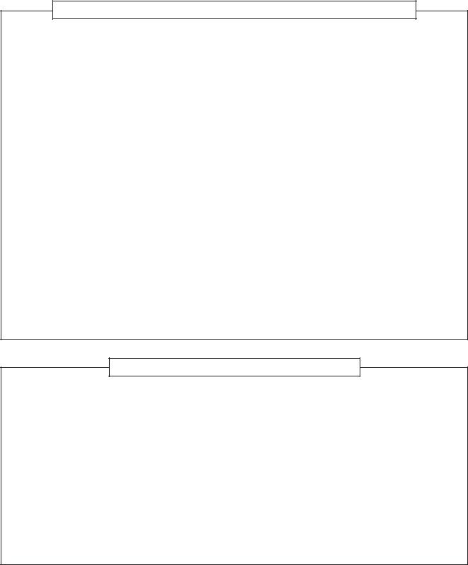
1-2. Operation Characteristic Curve
• Operation Characteristic Curve <Digital Inverter>
RAV-SM1103AT-E1,RAV-SM1403AT-E1 |
|
|
|
|
|
|
|
|
|
||||||
<Cooling> |
|
|
|
|
|
<Heating> |
|
|
|
|
|
||||
|
22 |
|
|
|
|
|
|
|
22 |
|
|
|
|
|
|
|
20 |
|
|
|
|
|
|
|
20 |
|
|
|
|
|
|
|
18 |
RAV-SM1103AT-E1 |
|
|
|
|
|
18 |
|
|
|
|
|
|
|
|
16 |
|
|
|
RAV-SM1403AT403AT--E1E |
|
16 |
RAVRAV--SM1403ATSM1403AT--E1E |
|
|
|
||||
|
|
|
|
|
|
|
|
|
|
|
|||||
|
|
|
|
|
|
|
|
|
|
|
|
|
|||
|
14 |
|
|
|
|
|
|
|
14 |
|
|
|
|
|
|
(A) |
12 |
|
|
|
|
|
|
(A) |
12 |
|
|
|
|
|
|
Current |
|
|
|
|
|
|
Current |
|
|
|
|
|
|
||
10 |
|
|
|
|
|
|
10 |
|
|
|
|
|
|
||
|
|
|
|
|
|
|
|
|
RAV-SM1103AT-E1 |
|
|
||||
|
8 |
|
|
|
|
|
|
|
8 |
|
|
|
|||
|
|
|
|
|
|
|
|
|
|
|
|
|
|
||
|
6 |
|
|
|
|
|
|
|
6 |
|
|
|
|
|
|
|
|
|
|
• Conditions |
|
|
|
|
|
|
• Conditions |
|
|
||
|
4 |
|
|
Indoor : DB27˚C/WB19˚C |
|
|
4 |
|
|
Indoor : DB20˚C |
|
||||
|
|
|
|
Outdoor : DB35˚C |
|
|
|
|
|
Outdoor : DB7˚C/WB6˚C |
|
||||
|
2 |
|
|
Air flow : High |
|
|
|
2 |
|
|
Air flow : High |
|
|
||
|
|
|
Pipe length : 7.5m |
|
|
|
|
Pipe length : 7.5m |
|
||||||
|
|
|
|
230V |
|
|
|
|
|
|
230V |
|
|
|
|
|
0 |
20 |
40 |
60 |
80 |
100 |
120 |
|
0 |
20 |
40 |
60 |
80 |
100 |
120 |
|
0 |
|
0 |
||||||||||||
Compressor speed (rps) |
Compressor speed (rps) |
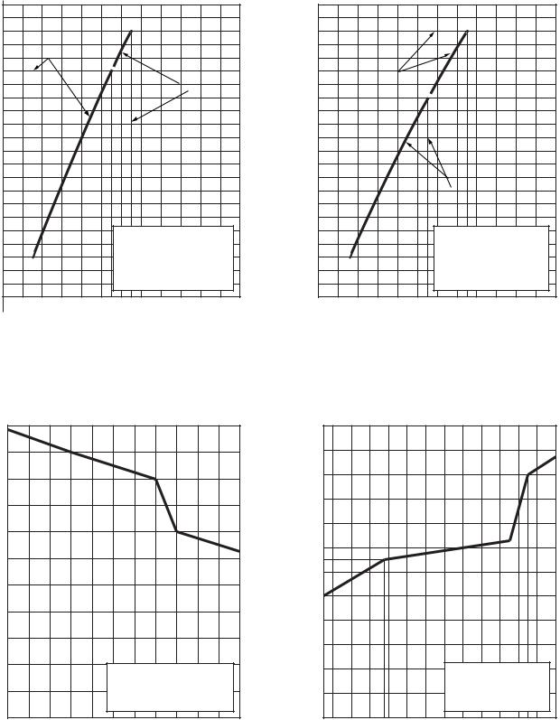
• Capacity variation ratio according to temperature
RAV-SM1103AT-E1,RAVSM1403AT-E1
<Cooling> |
|
|
|
|
|
|
|
|
<Heating> |
|
|
|
|
|
|
|
|
|
|
|||
|
105 |
|
|
|
|
|
|
|
|
|
|
120 |
|
|
|
|
|
|
|
|
|
|
|
100 |
|
|
|
|
|
|
|
|
|
|
110 |
|
|
|
|
|
|
|
|
|
|
|
95 |
|
|
|
|
|
|
|
|
|
|
100 |
|
|
|
|
|
|
|
|
|
|
|
|
|
|
|
|
|
|
|
|
|
|
|
|
|
|
|
|
|
|
|
|
|
|
90 |
|
|
|
|
|
|
|
|
|
|
90 |
|
|
|
|
|
|
|
|
|
|
|
|
|
|
|
|
|
|
|
|
|
|
|
|
|
|
|
|
|
|
|
|
|
(%) |
85 |
|
|
|
|
|
|
|
|
|
(%) |
80 |
|
|
|
|
|
|
|
|
|
|
|
|
|
|
|
|
|
|
|
|
|
|
|
|
|
|
|
|
|
|
|||
|
|
|
|
|
|
|
|
|
|
|
|
|
|
|
|
|
|
|
|
|
|
|
ratio |
80 |
|
|
|
|
|
|
|
|
|
ratio |
70 |
|
|
|
|
|
|
|
|
|
|
|
|
|
|
|
|
|
|
|
|
|
|
|
|
|
|
|
|
|
|
|||
|
|
|
|
|
|
|
|
|
|
|
|
|
|
|
|
|
|
|
|
|
|
|
Capacity |
70 |
|
|
|
|
|
|
|
|
|
Capacity |
60 |
|
|
|
|
|
|
|
|
|
|
|
|
|
|
|
|
|
|
|
|
|
|
|
|
|
|
|
|
|
|
|||
|
75 |
|
|
|
|
|
|
|
|
|
|
50 |
|
|
|
|
|
|
|
|
|
|
|
|
|
|
|
|
|
|
|
|
|
|
|
|
|
|
|
|
|
|
|
|
|
|
|
|
|
|
|
|
|
|
|
|
|
40 |
|
|
|
|
|
|
|
|
|
|
|
65 |
|
|
|
|
|
|
|
|
|
|
30 |
|
|
|
|
|
|
|
|
|
|
|
|
|
|
|
|
|
|
|
|
|
|
|
|
|
|
|
|
|
|
|
|
|
|
60 |
|
|
|
|
• Conditions |
|
|
|
|
20 |
|
|
|
|
• Conditions |
|
|
|
|||
|
|
|
|
|
|
|
|
|
|
|
|
|
|
|
|
|
||||||
|
55 |
|
|
|
|
Indoor : DB27˚C/WB19˚C |
|
|
|
|
|
|
|
Indoor : DB20˚C |
|
|
||||||
|
|
|
|
|
Indoor air flow : High |
|
|
|
10 |
|
|
|
|
Indoor air flow : High |
|
|||||||
|
|
|
|
|
|
Pipe length : 7.5m |
|
|
|
|
|
|
|
|
Pipe length : 7.5m |
|
|
|||||
|
50 |
33 |
34 |
35 |
36 |
37 |
38 39 40 |
41 |
42 |
43 |
|
0 |
-8 |
-6 |
-4 |
-2 |
0 |
2 |
4 |
6 |
8 |
10 |
|
32 |
|
-14 -12 -10 |
|||||||||||||||||||
Outdoor temp. (˚C) |
Outdoor temp. (˚C) |
– 14 –
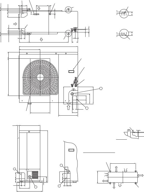
2 . CONSTRUCTION VIEWS (EXTERNAL VIEWS)
RAV-SM1103AT-E1, RAV-SM1403AT-E1
Knockout
(For draining) Drain hole (Ø20 × 88 Burring hole)
17.5 |
|
|
|
29 |
90 |
191 |
Drain hole (Ø25 Burring hole) |
|||
|
21 |
20 |
Part B |
|
|
|||||
|
|
|
Suction |
|
|
|
||||
|
|
|
|
|
|
port |
|
|
|
|
|
pitch |
bolt) |
70 |
Suction |
43 |
|
40 |
|
|
|
365 |
hole(Long |
anchorfor |
40 |
Knockout |
|
|
|
|
|
|
port |
|
|
|
|
|
|||||
|
|
|
|
(For draining) |
|
|
|
|
||
|
|
|
|
|
|
|
|
|
||
17.5 |
|
|
|
26 |
60 |
Discharge |
|
43 |
39 |
47 |
|
|
21 |
port |
Part A |
|
|
||||
|
|
|
150 |
600 |
95 |
|
|
|||
|
|
|
|
|
|
900 |
|
|
|
|
|
|
|
|
|
314 |
|
|
|
|
|
|
|
Installation bolt hole |
||||||
17.5 |
|
(Ø12 × 17 U-shape holes) |
||||||
|
|
|
|
|
|
|
|
|
|
|
|
40 |
|
|
|||
|
Details of B part |
|||||||
|
Details of A part |
|||||||
|
|
|
|
|
|
|
|
|
17.5 |
|
|
|
|
40 |
|
|
|
|
Installation bolt hole |
|||||||
|
||||||||
|
|
(Ø12 × 17 U-shape holes) |
||||||
|
|
|||||||
101
565
Discharge guide
mounting hole 300 (4-Ø4 Embossing)
28 320
|
|
795 |
1 |
|
|
90 |
25 |
89 |
60 |
2758
161 2
400
Handles (Both sides)
Refrigerant pipe connecting port
Flare at liquid side : Ø9.5
Refrigerant pipe connecting port
Flare at gas side : Ø15.9
2
264 |
60 67 |
154 |
264 |
Z |
60 27 |
1 |
|
307 |
96 |
|
|
|
|
|
Knockout for lower piping 86 7
58 7
Z views
|
|
Space required for service |
|
|
|
2-Ø12 × 17 U-shape holes |
|
|
|
(For Ø8–Ø10 Anchor bolt) |
|
|
2 |
46 |
150 moreor |
|
|
||
165 |
8060 |
365 |
150 |
|
|
|
or more |
1 |
25 |
50 |
500 |
|
|
|
|
|
|
|
or more |
600
Suction port
|
150 |
|
or more |
Discharge |
(Minimum |
port |
distance up to wall) |
Discharge |
2-Ø12 × 17 long hole |
|
port |
||
(For Ø8–Ø10 Anchor bolt) |
||
|
– 15 –
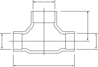
RBC-TWP30E2, RBC-TWP50E2 (Simultaneous Twin)
Inner diameter Ø C
|
B |
Inner |
Inner |
diameter Ø D |
diameter Ø D |
A
Model (RBC-) |
A |
B |
C |
D |
||
|
|
|
|
|
|
|
TWP30E2 |
Liquid side |
36 |
14 |
Ø9.5 |
Ø6.4 |
|
|
|
|
|
|
||
Gas side |
43 |
23 |
Ø15.9 |
Ø12.7 |
||
|
||||||
|
|
|
|
|
|
|
TWP50E2 |
Liquid side |
34 |
14 |
Ø9.5 |
Ø9.5 |
|
|
|
|
|
|
||
Gas side |
44 |
21 |
Ø15.9 |
Ø15.9 |
||
|
||||||
|
|
|
|
|
|
|
– 16 –

3 . REFRIGERATING CYCLE DIAGRAM
RAV-SM1103AT-E1, RAV-SM1403AT-E1
Outer diameter of refrigerant pipe |
|
|
|
Gas side ØA |
Liquid side ØB |
|
|
15.9mm |
9.5mm |
|
|
|
|
|
Indoor unit |
|
|
|
Height difference (m) |
|
Distributor |
||||
|
|
|||||
|
|
|
TCJ sensor |
|||
Outdoor unit |
Outdoor unit |
|
(Strainer incorporated) |
|||
at upper side |
at lower side |
Strainer |
|
|
|
|
30 |
30 |
Air heat exchanger |
|
|
|
|
|
TC sensor |
|||||
|
|
|
||||
|
|
|
||||
|
|
|
|
|||
|
|
|
Refrigerant pipe |
|
|
|
Refrigerant pipe |
|
|
difference |
|
at gas side Ø15.9 |
|
|
|
at liquid side Ø9.5 |
|
|
|
|
Section shape |
|
|
|
||
|
Height |
|
|
of heat insulator |
|
|
|
|
|
|
|
|
|
|
Min. |
Max. |
|
|
|
|
|
|
|
|
5m |
50m |
|
|
Ball valve |
|
|
|
Packed valve |
|
|
|
|
Outer dia. ØA |
Outdoor unit |
Outer dia. ØB |
|
|||
|
TS sensor |
|
|
|
|
|||
|
Strainer TO sensor |
|
PMV |
|
||||
|
|
|
|
|||||
|
Pressure |
|
|
|
|
(Pulse Motor Valve) |
|
|
|
|
|
|
|
(UKV-25D22) |
|
||
|
switch |
|
TL sensor |
|
|
|
||
|
P |
|
|
|
|
|
|
|
|
|
|
|
|
|
|
|
|
|
TD sensor |
|
|
|
|
|
|
|
|
|
|
|
|
|
|
Strainer |
|
|
4-way valve |
|
TE |
|
|
|
|
|
|
(STF-H0218) |
|
|
|
|
|
||
|
|
sensor |
|
|
|
|
||
|
|
|
|
|
|
|
|
|
|
Muffler |
|
Heat exchanger |
|
|
|
|
|
|
|
Outer side |
|
|
|
|
|
|
|
|
|
|
|
|
|
|
|
|
Ø25 × L210 |
Ø8, 2 rows, 20 steps |
Distributor |
|
||||
|
FP1.3 flat fin |
|
|
|||||
|
|
|
|
|
|
|||
Accumulator |
Ø25 × L180 |
Inner side |
|
|
|
|
|
|
(2500cc) |
Ø9.52 row, 30 steps |
|
|
|
|
|||
|
Rotary |
|
|
|
|
|
|
|
compressor |
FP1.5 flat fin |
||
|
|
|
|
(DA422A3F-12M) |
|
R410A 2.8kg |
|
|
|
||
|
|
|
Cooling |
|
|
|
|
|
|
|
Heating |
– 17 –
RAV-SM1103AT-E1
|
|
|
Pressure |
|
|
Pipe surface temp. |
|
* |
|
Temp |
||||
|
|
|
|
|
|
|
|
|
||||||
|
|
(MPa) |
(kg/cm2G) |
|
|
|
||||||||
|
|
|
|
|
|
|
|
|
|
|||||
|
|
|
|
|
|
|
Comp. |
|
|
|
||||
|
|
Pd |
Ps |
Pd |
Ps |
TD |
TS |
TC |
TL |
TE |
Hz |
Fan |
In |
Out |
|
|
|
|
|
|
|
|
|
|
|
|
|
|
|
|
Standard |
3.44 |
0.92 |
35.1 |
9.4 |
82 |
8 |
10 |
56 |
39 |
47 |
HIGH |
27/19 |
35/– |
|
|
|
|
|
|
|
|
|
|
|
|
|
|
|
Cooling |
Overload |
3.73 |
1.18 |
38.1 |
12.0 |
82 |
15 |
17 |
59 |
48 |
42 |
HIGH |
32/24 |
43/– |
|
|
|
|
|
|
|
|
|
|
|
|
|
|
|
|
Low load |
1.49 |
0.70 |
15.2 |
7.1 |
39 |
8 |
3 |
23 |
22 |
30 |
LOW |
18/15.5 |
–5/– |
|
|
|
|
|
|
|
|
|
|
|
|
|
|
|
|
Standard |
2.80 |
0.61 |
28.6 |
6.2 |
80 |
0 |
46 |
7 |
1 |
48 |
HIGH |
20/– |
7/6 |
|
|
|
|
|
|
|
|
|
|
|
|
|
|
|
Heating |
Overload |
3.43 |
1.08 |
35.0 |
11.0 |
82 |
14 |
55 |
12 |
13 |
24 |
LOW |
30/– |
24/18 |
|
|
|
|
|
|
|
|
|
|
|
|
|
|
|
|
Low load |
2.20 |
0.25 |
22.4 |
2.6 |
76 |
-19 |
36 |
-16 |
-16 |
55 |
HIGH |
15/– |
–10/(70%) |
|
|
|
|
|
|
|
|
|
|
|
|
|
|
|
RAV-SM1403AT-E1
|
|
|
Pressure |
|
|
Pipe surface temp. |
|
* |
|
Temp |
||||
|
|
|
|
|
|
|
|
|
||||||
|
|
(MPa) |
(kg/cm2G) |
|
|
|
||||||||
|
|
|
|
|
|
|
|
|
|
|||||
|
|
|
|
|
|
|
Comp. |
|
|
|
||||
|
|
|
|
|
|
|
|
|
|
|
|
|
|
|
|
|
Pd |
Ps |
Pd |
Ps |
TD |
TS |
TC |
TL |
TE |
Hz |
Fan |
In |
Out |
|
|
|
|
|
|
|
|
|
|
|
|
|
|
|
|
Standard |
3.52 |
0.85 |
35.9 |
8.7 |
87 |
8 |
9 |
57 |
39 |
54 |
HIGH |
27/19 |
35/– |
|
|
|
|
|
|
|
|
|
|
|
|
|
|
|
Cooling |
Overload |
3.78 |
1.12 |
38.6 |
11.4 |
84 |
15 |
17 |
59 |
47 |
45 |
HIGH |
32/24 |
43/– |
|
|
|
|
|
|
|
|
|
|
|
|
|
|
|
|
Low load |
1.51 |
0.71 |
15.4 |
7.2 |
40 |
7 |
3 |
23 |
23 |
30 |
LOW |
18/15.5 |
–5/– |
|
|
|
|
|
|
|
|
|
|
|
|
|
|
|
|
Standard |
2.88 |
0.60 |
29.4 |
6.1 |
85 |
1 |
47 |
6 |
1 |
61 |
HIGH |
20/– |
7/6 |
|
|
|
|
|
|
|
|
|
|
|
|
|
|
|
Heating |
Overload |
3.41 |
1.08 |
34.8 |
11.0 |
81 |
14 |
54 |
13 |
13 |
24 |
LOW |
30/– |
24/18 |
|
|
|
|
|
|
|
|
|
|
|
|
|
|
|
|
Low load |
2.35 |
0.24 |
24.0 |
2.4 |
80 |
-19 |
40 |
-16 |
-16 |
73 |
HIGH |
15/– |
–10/(70%) |
|
|
|
|
|
|
|
|
|
|
|
|
|
|
|
*4 poles are provided to this compressor.
The compressor frequency (Hz) measured with a clamp meter is 2 times of revolutions (rps) of the compressor.
– 18 –

4. WIRING DIAGRAM
– 19 –
5. SPECIFICATIONS OF ELECTRIC PARTS
Part name |
Type |
Specifications |
|
|
|
Compressor |
DA422A3F-12M |
|
|
|
|
Outdoor fan motor |
WDF-340-A100-1 |
Output 100W |
|
|
|
Reactor |
CH62-2Z-T |
6mH, 18.5A |
|
|
|
4-way valve coil |
STF-H01AJ1949A1 |
AC230V |
|
|
|
High-pressure SW |
ACB-4UB83W |
OFF: 4.15MPa |
|
|
|
PMV coil |
UKV-A039 |
DC12V |
|
|
|
P.C. board |
MCC-1630 |
1Ø AC220V/230V/240V±10%, 50/60HZ |
|
|
|
Fuse |
GDT 250V25A |
AC250V, 25A |
|
|
|
Fuse |
50T (P) 063HF |
AC250V, 6.3A |
|
|
|
Fuse |
SCT3.15A |
AC250V, 3.15A |
|
|
|
Surge absorber |
DA38-362MT or |
Discharge voltage 3600V |
|
DA38-302MT |
Discharge voltage 3000V |
|
|
|
Rectifier |
D25XB60 |
DC600V, 25A |
|
|
|
Electrolytic condenser |
LLQ2G761KHUATF or |
DC400V, 760μF |
|
ECST401LIN761KA58 |
|
|
|
|
Power relay |
DW12D1 |
AC250V, 20A x 2 |
|
|
|
Relay |
G5NB or |
AC250V, 3A |
|
DQ12D1 or |
AC250V, 5A |
|
RPG-12 |
AC250V, 3A |
|
|
|
Switching transformer |
SWT-91 |
Input: DC240 to 390V |
|
|
Output: DC7V, DC13V, DC17V |
|
|
|
Fuse |
50T100H |
AC250V, 10A |
|
|
|
– 20 –
6. REFRIGERANT R410A
This air conditioner adopts the new refrigerant HFC (R410A) which does not damage the ozone layer.
The working pressure of the new refrigerant R410A is 1.6 times higher than conventional refrigerant (R22). The refrigerating oil is also changed in accordance with change of refrigerant, so be careful that water, dust, and existing refrigerant or refrigerating oil are not entered in the refrigerant cycle of the air conditioner using the new refrigerant during installation work or servicing time.
The next section describes the precautions for air conditioner using the new refrigerant.
Conforming to contents of the next section together with the general cautions included in this manual, perform the correct and safe work.
6-1. Safety During Installation/Servicing
As R410A’s pressure is about 1.6 times higher than that of R22, improper installation/servicing may cause a serious trouble. By using tools and materials exclusive for R410A, it is necessary to carry out installation/servicing safely while taking the following precautions into consideration.
1.Never use refrigerant other than R410A in an air conditioner which is designed to operate with R410A.
If other refrigerant than R410A is mixed, pressure in the refrigeration cycle becomes abnormally high, and it may cause personal injury, etc. by a rupture.
2.Confirm the used refrigerant name, and use tools and materials exclusive for the refrigerant R410A.
The refrigerant name R410A is indicated on the visible place of the outdoor unit of the air conditioner using R410A as refrigerant.
To prevent mischarging, the diameter of the service port differs from that of R22.
3.If a refrigeration gas leakage occurs during installation/servicing, be sure to ventilate fully.
If the refrigerant gas comes into contact with fire, a poisonous gas may occur.
4.When installing or removing an air conditioner, do not allow air or moisture to remain in the refrigeration cycle.
Otherwise, pressure in the refrigeration cycle may become abnormally high so that a rupture or personal injury may be caused.
5.After completion of installation work, check to make sure that there is no refrigeration gas leakage.
If the refrigerant gas leaks into the room, coming into contact with fire in the fan-driven heater, space heater, etc., a poisonous gas may occur.
6.When an air conditioning system charged with a large volume of refrigerant is installed in a small room, it is necessary to exercise care so that, even when refrigerant leaks, its concentration does not exceed the marginal level.
If the refrigerant gas leakage occurs and its concentration exceeds the marginal level, an oxygen starvation accident may result.
7.Be sure to carry out installation or removal according to the installation manual.
Improper installation may cause refrigeration trouble, water leakage, electric shock, fire, etc.
8.Unauthorized modifications to the air conditioner may be dangerous. If a breakdown occurs please call a qualified air conditioner technician or electrician.
Improper repair may result in water leakage, electric shock and fire, etc.
6-2. Refrigerant Piping Installation
6-2-1. Piping Materials and Joints Used
For the refrigerant piping installation, copper pipes and joints are mainly used.
Copper pipes and joints suitable for the refrigerant must be chosen and installed.
Furthermore, it is necessary to use clean copper pipes and joints whose interior surfaces are less affected by contaminants.
1.Copper Pipes
It is necessary to use seamless copper pipes which are made of either copper or copper alloy and it is desirable that the amount of residual oil is less than 40 mg/10 m.
Do not use copper pipes having a collapsed, deformed or discolored portion (especially on the interior surface).
Otherwise, the expansion valve or capillary tube may become blocked with contaminants.
As an air conditioner using R410A incurs pressure higher than when using R22, it is necessary to choose adequate materials.
Thicknesses of copper pipes used with R410A are as shown in Table 6-2-1. Never use copper pipes thinner than 0.8mm even when it is available on the market.
NOTE
Refer to the “6-6. Instructions for Re-use Piping of R22 or R407C”.
– 21 –
Table 6-2-1 Thicknesses of annealed copper pipes
|
|
|
Thickness (mm) |
|
|
|
|
Nominal diameter |
Outer diameter (mm) |
R410A |
R22 |
|
|
|
|
1/4 |
6.4 |
0.80 |
0.80 |
|
|
|
|
3/8 |
9.5 |
0.80 |
0.80 |
|
|
|
|
1/2 |
12.7 |
0.80 |
0.80 |
|
|
|
|
5/8 |
15.9 |
1.00 |
1.00 |
|
|
|
|
1.Joints
For copper pipes, flare joints or socket joints are used. Prior to use, be sure to remove all contaminants.
a)Flare Joints
Flare joints used to connect the copper pipes cannot be used for pipings whose outer diameter exceeds 20 mm. In such a case, socket joints can be used.
Sizes of flare pipe ends, flare joint ends and flare nuts are as shown in Tables 6-2-3 to 6-2-5 below.
b)Socket Joints
Socket joints are such that they are brazed for connections, and used mainly for thick pipings whose diameter is larger than 20 mm. Thicknesses of socket joints are as shown in Table 6-2-2.
|
Table 6-2-2 |
Minimum thicknesses of socket joints |
||
|
|
|
|
|
Nominal diameter |
|
Reference outer diameter of |
Minimum joint thickness |
|
|
|
copper pipe jointed (mm) |
(mm) |
|
|
|
|
||
|
|
|
|
|
1/4 |
|
|
6.4 |
0.50 |
|
|
|
|
|
3/8 |
|
|
9.5 |
0.60 |
|
|
|
|
|
1/2 |
|
|
12.7 |
0.70 |
|
|
|
|
|
5/8 |
|
|
15.9 |
0.80 |
|
|
|
|
|
6-2-2. Processing of Piping Materials
When performing the refrigerant piping installation, care should be taken to ensure that water or dust does not enter the pipe interior, that no other oil other than lubricating oils used in the installed air conditioner is used, and that refrigerant does not leak.
When using lubricating oils in the piping processing, use such lubricating oils whose water content has been removed. When stored, be sure to seal the container with an airtight cap or any other cover.
1.Flare Processing Procedures and Precautions
a)Cutting the Pipe
By means of a pipe cutter, slowly cut the pipe so that it is not deformed.
b)Removing Burrs and Chips
If the flared section has chips or burrs, refrigerant leakage may occur. Carefully remove all burrs and clean the cut surface before installation.
– 22 –

c)Insertion of Flare Nut
d)Flare Processing
Make certain that a clamp bar and copper pipe have been cleaned.
By means of the clamp bar, perform the flare processing correctly. Use either a flare tool for R410A or conventional flare tool.
Flare processing dimensions differ according to the type of flare tool.
When using a conventional flare tool, be sure to secure “dimension A” by using a gauge for size adjustment.
ØD |
A |
|
|
|
|
Fig. 6-2-1 Flare processing dimensions |
||||
|
Table 6-2-3 Dimensions related to flare processing for R410A / R22 |
|
||||||
|
|
|
|
|
|
|
|
|
|
|
|
|
|
A (mm) |
|
|
|
|
Outer |
|
|
|
|
|
|
|
Nominal |
Thickness |
|
Conventional flare tool |
Conventional flare tool |
||||
diameter |
Flare tool for |
|||||||
diameter |
(mm) |
(R410A) |
(R22) |
|||||
(mm) |
R410A, R22 |
|||||||
|
|
|
|
|
|
|||
|
|
|
clutch type |
Clutch type |
Wing nut type |
Clutch type |
Wing nut type |
|
|
|
|
|
|||||
|
|
|
|
|
|
|
|
|
1/4 |
6.4 |
0.8 |
0 to 0.5 |
1.0 to 1.5 |
1.5 to 2.0 |
0.5 to 1.0 |
1.0 to 1.5 |
|
|
|
|
|
|
|
|
|
|
3/8 |
9.5 |
0.8 |
0 to 0.5 |
1.0 to 1.5 |
1.5 to 2.0 |
0.5 to 1.0 |
1.0 to 1.5 |
|
|
|
|
|
|
|
|
|
|
1/2 |
12.7 |
0.8 |
0 to 0.5 |
1.0 to 1.5 |
2.0 to 2.5 |
0.5 to 1.0 |
1.5 to 2.0 |
|
|
|
|
|
|
|
|
|
|
5/8 |
15.9 |
1.0 |
0 to 0.5 |
1.0 to 1.5 |
2.0 to 2.5 |
0.5 to 1.0 |
1.5 to 2.0 |
|
|
|
|
|
|
|
|
|
|
3/4 |
19.1 |
1.2 |
0 to 0.5 |
1.0 to 1.5 |
2.0 to 2.5 |
— |
— |
|
|
|
|
|
|
|
|
|
|
|
Table 6-2-4 |
Flare and flare nut dimensions for R410A |
|
|
|||||
|
|
|
|
|
|
|
|
|
|
Nominal |
Outer diameter |
|
Thickness |
|
Dimension (mm) |
|
Flare nut width |
||
|
|
|
|
|
|
||||
diameter |
(mm) |
|
(mm) |
A |
B |
C |
|
D |
(mm) |
|
|
|
|
|
|
||||
|
|
|
|
|
|
|
|
|
|
1/4 |
6.4 |
|
0.8 |
9.1 |
9.2 |
6.5 |
|
13 |
17 |
|
|
|
|
|
|
|
|
|
|
3/8 |
9.5 |
|
0.8 |
13.2 |
13.5 |
9.7 |
|
20 |
22 |
|
|
|
|
|
|
|
|
|
|
1/2 |
12.7 |
|
0.8 |
16.6 |
16.0 |
12.9 |
|
23 |
26 |
|
|
|
|
|
|
|
|
|
|
5/8 |
15.9 |
|
1.0 |
19.7 |
19.0 |
16.0 |
|
25 |
29 |
|
|
|
|
|
|
|
|
|
|
3/4 |
19.1 |
|
1.2 |
24.0 |
— |
19.2 |
|
28 |
36 |
|
|
|
|
|
|
|
|
|
|
|
Table 6-2-5 |
Flare and flare nut dimensions for R22 |
|
|
|||||
|
|
|
|
|
|
|
|
|
|
Nominal |
Outer diameter |
|
Thickness |
|
Dimension (mm) |
|
Flare nut width |
||
|
|
|
|
|
|
||||
diameter |
(mm) |
|
(mm) |
A |
B |
C |
|
D |
(mm) |
|
|
|
|
|
|
||||
|
|
|
|
|
|
|
|
|
|
1/4 |
6.4 |
|
0.8 |
9.1 |
9.2 |
6.5 |
|
13 |
17 |
|
|
|
|
|
|
|
|
|
|
3/8 |
9.5 |
|
0.8 |
13.0 |
13.5 |
9.7 |
|
20 |
22 |
|
|
|
|
|
|
|
|
|
|
1/2 |
12.7 |
|
0.8 |
16.2 |
16.0 |
12.9 |
|
20 |
24 |
|
|
|
|
|
|
|
|
|
|
5/8 |
15.9 |
|
1.0 |
19.4 |
19.0 |
16.0 |
|
23 |
27 |
|
|
|
|
|
|
|
|
|
|
3/4 |
19.1 |
|
1.0 |
23.3 |
24.0 |
19.2 |
|
34 |
36 |
|
|
|
|
|
|
|
|
|
|
– 23 –
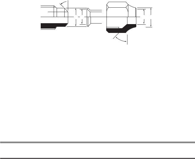
46˚ 45˚to 
A B |
C D |
43˚to |
45˚ |
|
Fig. 6-2-2 Relations between flare nut and flare seal surface
2.Flare Connecting Procedures and Precautions
a)Make sure that the flare and union portions do not have any scar or dust, etc.
b)Correctly align the processed flare surface with the union axis.
c)Tighten the flare with designated torque by means of a torque wrench. The tightening torque for R410A is the same as that for conventional R22. Incidentally, when the torque is weak, the gas leakage may occur.
When it is strong, the flare nut may crack and may be made non-removable.
When choosing the tightening torque, comply with values designated by manufacturers. Table 6-2-6 shows reference values.
NOTE
When applying oil to the flare surface, be sure to use oil designated by the manufacturer.
If any other oil is used, the lubricating oils may deteriorate and cause the compressor to burn out.
Table 6-2-6 Tightening torque of flare for R410A [Reference values]
Nominal |
Outer diameter |
Tightening torque |
Tightening torque of torque |
||
wrenches available on the market |
|||||
diameter |
(mm) |
N•m (kgf•m) |
|||
N•m (kgf•m) |
|||||
|
|
|
|
||
|
|
|
|
|
|
1/4 |
6.4 |
14 to 18 |
(1.4 to 1.8) |
16 (1.6), 18 (1.8) |
|
|
|
|
|
|
|
3/8 |
9.5 |
33 to 42 |
(3.3 to 4.2) |
42 (4.2) |
|
|
|
|
|
|
|
1/2 |
12.7 |
50 to 62 |
(5.0 to 6.2) |
55 (5.5) |
|
|
|
|
|
|
|
5/8 |
15.9 |
63 to 77 |
(6.3 to 7.7) |
65 (6.5) |
|
|
|
|
|
|
|
3/4 |
19.1 |
100 to 120 |
(10.0 to 12.0) |
—— |
|
|
|
|
|
|
|
– 24 –
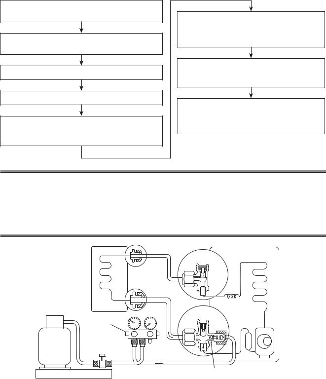
6-3. Tools
6-3-1. Required Tools
Refer to the “4. Tools”
6-4. Recharging of Refrigerant
When it is necessary to recharge refrigerant, charge the specified amount of new refrigerant according to the following steps.
Recover the refrigerant, and check no refrigerant remains in the equipment.
Connect the charge hose to packed valve service port at the outdoor unit’s gas side.
Connect the charge hose of the vacuum pump adapter.
Open fully both packed valves at liquid and gas sides.
Place the handle of the gauge manifold Low in the fully opened position, and turn on the vacuum pump’s power switch.
Then, evacuating the refrigerant in the cycle.
When the compound gauge’s pointer has indicated –0.1 Mpa (–76 cmHg), place the handle Low in the fully closed position, and turn off the vacuum pump’s power switch.
Keep the status as it is for 1 to 2 minutes, and ensure that the compound gauge’s pointer does not return.
Set the refrigerant cylinder to the electronic balance, connect the connecting hose to the cylinder and
the connecting port of the electronic balance, and charge liquid refrigerant.
(For refrigerant charging, see the figure below.)
1)Never charge refrigerant exceeding the specified amount.
2)If the specified amount of refrigerant cannot be charged, charge refrigerant bit by bit in COOL mode.
3)Do not carry out additional charging.
When additional charging is carried out if refrigerant leaks, the refrigerant composition changes in the refrigeration cycle, that is characteristics of the air conditioner changes, refrigerant exceeding the specified amount is charged, and working pressure in the refrigeration cycle becomes abnormally high pressure, and may cause a rupture or personal injury.
(INDOOR unit) |
(Liquid side) |
(OUTDOOR unit) |
Opened
(Gas side)
Refrigerant cylinder (With siphon pipe)
Check valve
Closed
Open/Close valve for charging
Service port
Electronic balance for refrigerant charging
Fig. 6-4-1 Configuration of refrigerant charging
– 25 –
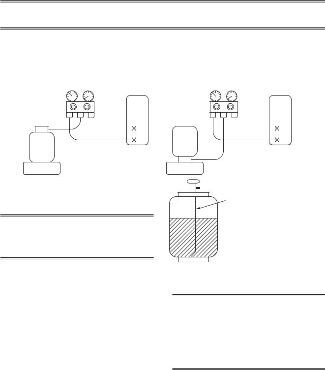
1)Be sure to make setting so that liquid can be charged.
2)When using a cylinder equipped with a siphon, liquid can be charged without turning it upside down.
It is necessary for charging refrigerant under condition of liquid because R410A is mixed type of refrigerant.
Accordingly, when charging refrigerant from the refrigerant cylinder to the equipment, charge it turning the cylinder upside down if cylinder is not equipped with siphon.
[ Cylinder with siphon ] |
[ Cylinder without siphon ] |
Gauge manifold |
Gauge manifold |
OUTDOOR unit |
OUTDOOR unit |
Refrigerant
cylinder
Electronic
balance
cylinder Refrigerant
Electronic
balance
Siphon
R410A refrigerant is HFC mixed refrigerant.
Therefore, if it is charged with gas, the composition of the charged refrigerant changes and the characteristics of the equipment varies.
Fig. 6-4-2
6-5. Brazing of Pipes
6-5-1. Materials for Brazing
1.Silver brazing filler
Silver brazing filler is an alloy mainly composed of silver and copper.
It is used to join iron, copper or copper alloy, and is relatively expensive though it excels in solderability.
1)Phosphor bronze brazing filler tends to react with sulfur and produce a fragile compound water solution, which may cause a gas leakage. Therefore, use any other type of brazing filler at a hot spring resort, etc., and coat the surface with a paint.
2)When performing brazing again at time of servicing, use the same type of brazing filler.
2. Phosphor bronze brazing filler |
6-5-2. Flux |
|
Phosphor bronze brazing filler is generally used to join copper or copper alloy.
3.Low temperature brazing filler
Low temperature brazing filler is generally called solder, and is an alloy of tin and lead.
Since it is weak in adhesive strength, do not use it for refrigerant pipes.
1.Reason why flux is necessary
•By removing the oxide film and any foreign matter on the metal surface, it assists the flow of brazing filler.
•In the brazing process, it prevents the metal surface from being oxidized.
•By reducing the brazing filler's surface tension, the brazing filler adheres better to the treated metal.
– 26 –
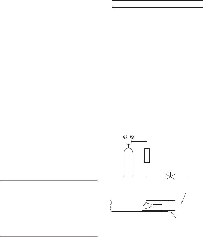
2.Characteristics required for flux
•Activated temperature of flux coincides with the brazing temperature.
•Due to a wide effective temperature range, flux is hard to carbonize.
•It is easy to remove slag after brazing.
•The corrosive action to the treated metal and brazing filler is minimum.
•It excels in coating performance and is harmless to the human body.
As the flux works in a complicated manner as described above, it is necessary to select an adequate type of flux according to the type and shape of treated metal, type of brazing filler and brazing method, etc.
3.Types of flux
•Noncorrosive flux
Generally, it is a compound of borax and boric acid.
It is effective in case where the brazing temperature is higher than 800°C.
•Activated flux
Most of fluxes generally used for silver brazing are this type.
It features an increased oxide film removing capability due to the addition of compounds such as potassium fluoride, potassium chloride and sodium fluoride to the borax-boric acid compound.
4.Piping materials for brazing and used brazing filler/flux
Piping material |
Used brazing filler |
Used flux |
|
|
|
Copper - Copper |
Phosphor copper |
Do not use |
|
|
|
Copper - Iron |
Silver |
Paste flux |
|
|
|
Iron - Iron |
Silver |
Vapor flux |
|
|
|
1)Do not enter flux into the refrigeration cycle.
2)When chlorine contained in the flux remains within the pipe, the lubricating oil deteriorates.
Therefore, use a flux which does not contain chlorine.
3)When adding water to the flux, use water which does not contain chlorine
(e.g. distilled water or ion-exchange water).
4)Remove the flux after brazing.
6-5-3. Brazing
As brazing work requires sophisticated techniques, experiences based upon a theoretical knowledge, it must be performed by a person qualified.
In order to prevent the oxide film from occurring in the pipe interior during brazing, it is effective to proceed with brazing while letting dry Nitrogen gas flow.
Never use gas other than Nitrogen gas.
1.Brazing method to prevent oxidation
1)Attach a reducing valve and a flow-meter to the Nitrogen gas cylinder.
2)Use a copper pipe to direct the piping material, and attach a flow-meter to the cylinder.
3)Apply a seal onto the clearance between the piping material and inserted copper pipe for Nitrogen in order to prevent backflow of the Nitrogen gas.
4)When the Nitrogen gas is flowing, be sure to keep the piping end open.
5)Adjust the flow rate of Nitrogen gas so that it is lower than 0.05 m³/Hr or 0.02 MPa (0.2kgf/cm²) by means of the reducing valve.
6)After performing the steps above, keep the Nitrogen gas flowing until the pipe cools down to a certain extent (temperature at which pipes are touchable with hands).
7)Remove the flux completely after brazing.
M Flow meter
Stop valve
Nitrogen gas cylinder
From Nitrogen cylinder
Pipe 

 Nitrogen gas
Rubber plug
Fig. 6-5-1
Prevention of oxidation during brazing
– 27 –
6-6. Instructions for Re-use Piping of R22 or R407C
Instruction of Works:
The existing R22 and R407C piping can be reused for our digital inverter R410A products installations.
NOTE)
Confirmation of existence of scratch or dent of the former pipes to be applied and also confirmation of reliability of the pipe strength are conventionally referred to the local site.
If the definite conditions can be cleared,
it is possible to update the existing R22 and R407C pipes to those for R410A models.
6-6-1. Basic Conditions Needed to Reuse the Existing Pipe
Check and observe three conditions of the refrigerant piping works.
1. |
Dry |
(There is no moisture inside of the pipes.) |
2. |
Clean |
(There is no dust inside of the pipes.) |
3. |
Tight |
(There is no refrigerant leak.) |
6-6-2. Restricted Items to Use the Existing Pipes
In the following cases, the existing pipes cannot be reused as they are. Clean the existing pipes or exchange them with new pipes.
1.When a scratch or dent is heavy, be sure to use the new pipes for the works.
2.When the thickness of the existing pipe is thinner than the specified “Pipe diameter and thickness” be sure to use the new pipes for the works.
•The operating pressure of R410A is high
(1.6 times of R22 and R407C). If there is a scratch or dent on the pipe or thinner pipe is used, the pressure strength is poor and may cause breakage of the pipe at the worst.
Pipe diameter and thickness (mm)
Pipe outer diameter |
Ø6.4 |
Ø9.5 |
Ø12.7 |
Ø15.9 |
Ø19.0 |
||
|
|
|
|
|
|
|
|
|
R410A |
|
|
|
|
|
|
Thickness |
|
0.8 |
0.8 |
0.8 |
1.0 |
1.0 |
|
R22 |
|||||||
|
|
|
|
|
|||
|
(R407C) |
|
|
|
|
|
|
|
|
|
|
|
|
|
|
•In case that the pipe diameter is Ø12.7 mm or less and the thickness is less than 0.7 mm, be sure to use the new pipes for works.
3.The pipes are left as coming out or gas leaks. (Poor refrigerant)
•There is possibility that rain water or air including moisture enters in the pipe.
4.Refrigerant recovery is impossible.
(Refrigerant recovery by the pump-down operation on the existing air conditioner)
•There is possibility that a large quantity of poor oil or moisture remains inside of the pipe.
5.A dryer on the market is attached to the existing pipes.
•There is possibility that copper green rust generated.
6.Check the oil when the existing air conditioner was removed after refrigerant had been recovered.
In this case, if the oil is judged as clearly different compared with normal oil
•The refrigerator oil is copper rust green :
There is possibility that moisture is mixed with the oil and rust generates inside of the pipe.
•There is discolored oil, a large quantity of the remains, or bad smell.
•A large quantity of sparkle remained wear-out powder is observed in the refrigerator oil.
7.The air conditioner which compressor was exchanged due to a faulty compressor.
When the discolored oil, a large quantity of the remains, mixture of foreign matter, or a large quantity of sparkle remained wear-out powder is observed, the cause of trouble will occur.
8.Installation and removal of the air conditioner are repeated with temporary installation by lease and etc.
9.In case that type of the refrigerator oil of the existing air conditioner is other than the following oil (Mineral oil), Suniso, Freol-S, MS (Synthetic oil), alkyl benzene (HAB, Barrel-freeze), ester series, PVE only of ether series.
•Winding-insulation of the compressor may become inferior.
NOTE)
The above descriptions are results of confirmation by our company and they are views on our air conditioners, but they do not guarantee the use of the existing pipes of the air conditioner that adopted R410A in other companies.
6-6-3. Branching Pipe for Simultaneous Operation System
•In the concurrent twin system, when TOSHIBAspecified branching pipe is used, it can be reused. Branching pipe model name:
RBC-TWP30E2, RBC-TWP50E2
On the existing air conditioner for simultaneous operation system (twin system), there is a case of using branch pipe that has insufficient compressive strength. In this case please change it to the branch pipe for R410A.
6-6-4. Curing of Pipes
When removing and opening the indoor unit or outdoor unit for a long time, cure the pipes as follows:
•Otherwise rust may generate when moisture or foreign matter due to dewing enters in the pipes.
•The rust cannot be removed by cleaning, and a new piping work is necessary.
Place position |
Term |
Curing manner |
|
|
|
|
|
Outdoors |
1 month or more |
Pinching |
|
|
|
||
Less than 1 month |
Pinching or taping |
||
|
|||
|
|
||
Indoors |
Every time |
||
|
|||
|
|
|
– 28 –
 Loading...