


01_VS470_en 24/08/04 10:34 Page 1
Wireless video transmitter
Precautions
Safety
• This equipment contains heat sensitive components. Maximum ambient temperature must EN not exceed 35° Celsius.
•Humidity in rooms where this equipment is situated must not exceed a hygrometric level of 85 %. If you have to use your equipment outside, avoid exposing it to rain water or to splashes.The transition from a cold environment to a hot one may cause condensation.Allow it to dry by itself before re-starting the equipment.
•In the event of prolonged absence, switch off the equipment by means of the on/off switch. Even when switched off, certain components remain live. In order to insulate it completely you must remove the plug from the main electricity supply.
•In the event of an electrical storm, it is advisable to disconnect the equipment from the electricity supply so as to avoid potentially damaging electrical or electromagnetic surges.To this
end, make sure that the mains plug is easily accessible for disconnection.
•Disconnect the equipment immediately if you detect a smell of burning or smoke. Under no circumstances must you open the equipment yourself; you run the risk of electrocution.
Maintenance
•Clean the equipment with a soft cloth and a neutral detergent. The use of solvents, abrasive products or alcohol-based products is likely to damage the equipment.
Regulations
•This equipment must only be installed inside. Its use is restricted to private radio transmission. Connection to a public or independent network, or to an outside aerial is prohibited.
Under no circumstances should this appliance be put to industrial use. It is designed solely for domestic operation.
THOMSON disclaims all responsibility in the event of use that does not comply with the present instructions.
1
01_VS470_en 24/08/04 10:34 Page 2
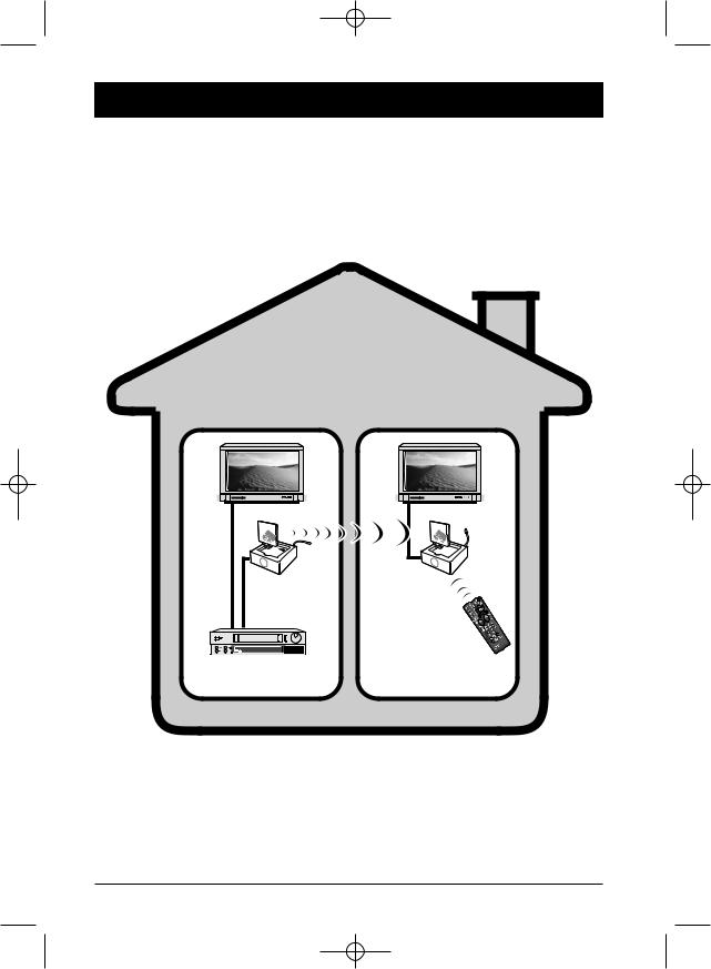
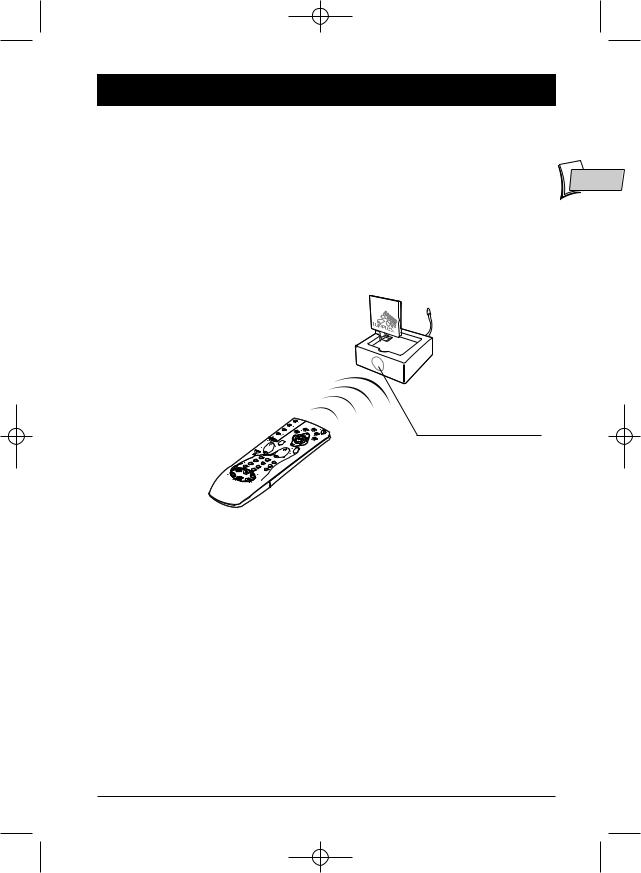
Principles of operation
LIVING ROOM |
BEDROOM |
Transmitter |
Receiver |
|
|
Remote control for |
|
Video recorder, |
video recorder, |
|
satellite receiver,…or |
||
satellite receiver,... |
||
universal remote control. |
||
|
2
01_VS470_en 24/08/04 10:34 Page 3
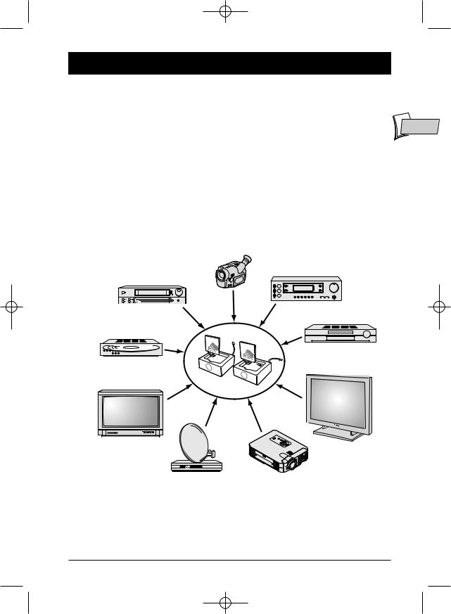
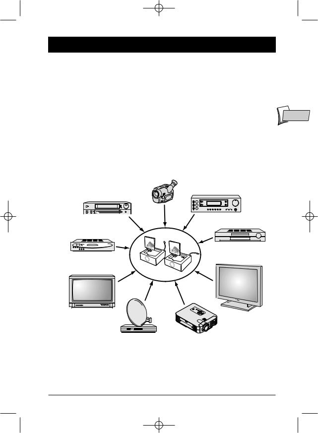
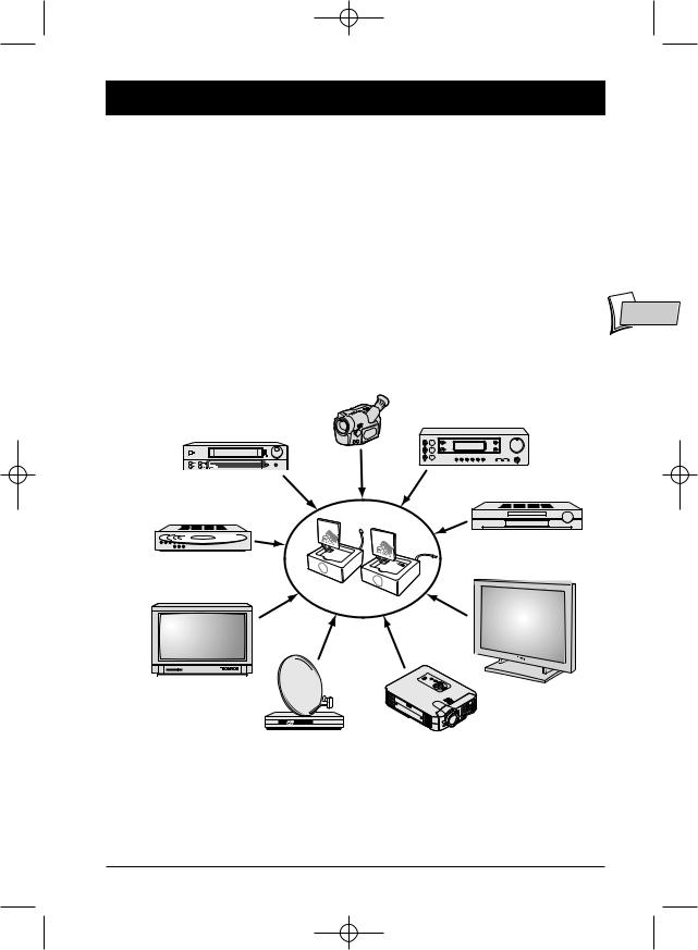
What is this equipment for?
The Video Sender VS 470 permits the relay of an Audio-Video signal from your main set-up to a |
|
second television set located in another room and equipped with a scart connection (or |
|
RCA/Cinch).The main set-up is the place in which you have chosen to install the majority of your |
|
equipment (television set, video recorder, satellite receiver, DVD player,..) you can operate the units |
|
from the room with the second television set by using their remote controls, or with a universal |
EN |
remote control. |
You can play and hear music if you connect the transmitter to a suitable outlet (AUDIO OUT), and the receiver to an amplifier (AUDIO IN) placed in another room.
If you already have a Thomson plasma screen monitor or video projector, theVideo Sender will ease your placing of these items where you most want them to be, thanks to eliminating all problems related to long cable runs.
Camcorder
A/V Amplifier
Video recorder
DVD player
Video disc player
Plasma screen monitor
Television set
Satellite/Cable receiver |
Video projector |
and decoder |
|
3
01_VS470_en 24/08/04 10:34 Page 4
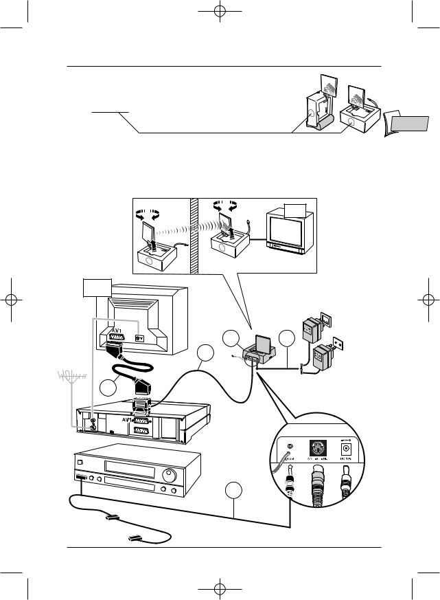
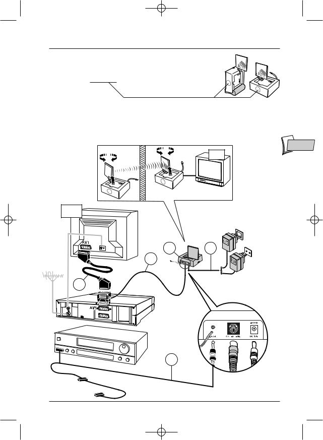
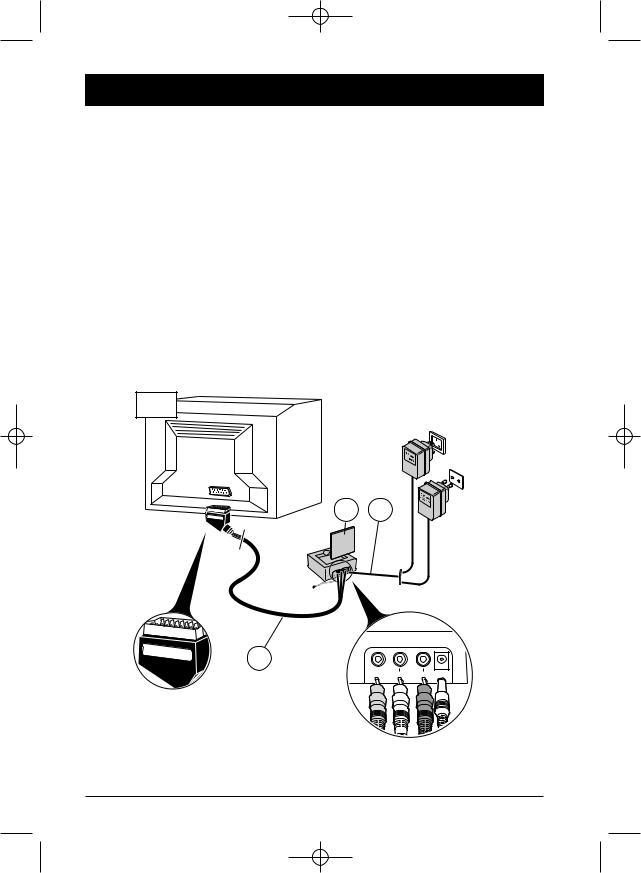
Installation of transmitter
Refer to the overall installation diagram inside the cover of the instruction booklet as well as the diagram on the following page.
1.Place the transmitter (1) near the source equipment (VCR player, DVD player, etc.) from which you want to transmit video or audio output, and connect it with the cord (2). Connect the TV set to a suitable outlet from the VCR player or DVD player (AV1).
Obtain a (non-supplied) SCART-TV set connector and connect the TV set to the (2) adapter already connected to the VCR player or DVD player as shown on Page 5 (see item marked * on Page 5).
2.Carefully extend the antenna of the transmitter (1) and orient it towards the room where your second TV set (TV2) is located.Turn on (position on) the transmitter, using the off/on switch located on its side. Place the channel selectors of the transmitter (and the receiver) on the same channel (same letter).
3.Fit the lead (4) following these stages:
-connect the jack plug to the IR ext socket,
-unwind the lead and place one cell near the infrared window of the unit to be operated (video recorder or other),
-after installing the receiver (see Pages 6 and 7), ask someone to use the remote control of that equipment item to be controlled from the room where the second (TV2) is located,
-by moving the cell around in front of the unit to be operated you will find the location that permits its control from the other room.You must fix the cell in that position. Usually, this will be a more or less large, transparent area located on the front of the unit.
4.Remove the protective self-adhesive film from the infrared cell of cord (4) and affix it to the infrared-sensitive panel of the equipment to be remote controlled. The cordon has 3 cells in order to let you play video and audio from 3 equipment items connected to the (TV1) set (see Diagram 2 on Page 10).
5.Fit the AC adaptator (3) to the transmitter and plug it into a 220/240 V ~ 50 Hz mains power supply.
Note:The AC Adaptors for the transmitter and receiver are different.The one provided for the transmitter is a 12V–200 mA model.
4
01_VS470_en 24/08/04 10:34 Page 5
Installation of transmitter
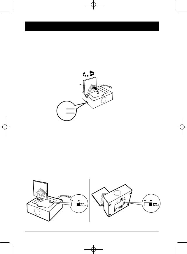
Installation of the transmitter:
Vertically by using the support or horizontally without the support.
Note: the IR window must be turned towards the user.
EN
Antenna:
Depending on the distance between the transmitter and the receiver, deploy the antenna and turn it so that the markings (WIRELESS) face each other. If the transmitter and the receiver are very close, it may not be necessary to deploy the antenna.
TV2
TV1
220/240V ~ 50 Hz
UNITED-
KINGDOM -
EIRE
1 3
2
CONTINENTAL EUROPE
*
4
5

01_VS470_en 24/08/04 10:34 Page 6
Installation of receiver
1.Place the receiver (5) on, or near, the second television set.
2.Connect the receiver (5) to the second television set using the lead (6) following the same instructions as for the transmitter.
3.Extend the antenna on the receiver (5) and orient it toward the main TV set (TV1).
4.Fit the AC adaptator (9V, 400mA) (7) to the receiver and plug it into a 220/240 V ~ 50 Hz mains power supply.
!THE ANTENNA allows you to transmit and receive audio and video signals over a maximum range of 80 meters in free air environments. Inside a typical lodgment the range will be less because of signal attenuation by building material absorption.
!THE FLEXIBLE ANTENNA permits the control of the unit whose pictures you wish to see in the
room containing the second television set (TV2).
! THE POWER SUPPLY plug fitted to the transmitter (1) is not the same as the one fitted to the receiver (7).
TV2
5 7
220/240V ~ 50 Hz
UNITED-
KINGDOM -
EIRE
CONTINENTAL
EUROPE
Receiver
Receiver
6
VIDEO OUT |
L AUDIO OUT R |
DC 9V |
6
01_VS470_en 24/08/04 10:34 Page 7
Instructions for use
1.Switch on the transmitter (1) and the receiver (5) by switching their off/on buttons to the on position.
2.Make sure that the transmitter and the receiver are set to the same channel by
checking the position of the selectors located under the casing or under the |
EN |
antenna.They must be set to the same channel (same letter). |
3.Switch on your equipment (television sets, video recorders ...) in both rooms.
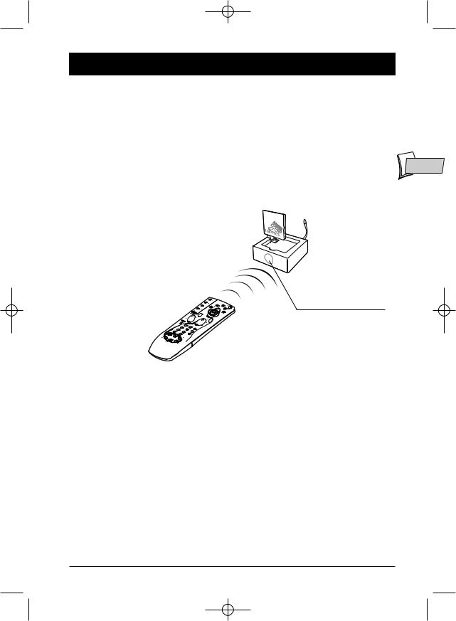
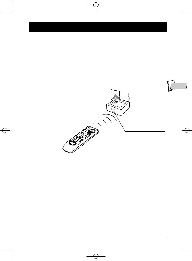
4.Using the remote control of the unit whose pictures you wish to see, and from the room containing the second television set (TV2), select the channels or video functions (or others) according to the unit you are controlling.
Receiver
Make sure that you point the remote control directly at the receiver’s (5) infrared window
Special operating details:
• No picture on TV2? If you fail to obtain the desired picture on the second television set TV2, select the AV socket, to which the receiver (5) is connected, using the television’s remote control.
•Using a decoder (in France: Canal +,TPS, etc.) on your TV2? To have clear images on your
second TV set (TV2), output from the decoder must pass through a VCR player, placed in (AV2) mode or set to the channel number assigned for the encrypted TV channel.
•Use of a monitor? If your second television set does not have a connection for an outside aerial (terrestrial reception), or if it is a monitor, you will be able to see the channels in the room containing the second television set by selecting those of the video recorder with its remote control.
•The picture is scrambled? The running of certain equipment (micro-wave ovens, digital telephone DECT, un-shielded acoustic loudspeakers, etc ...) may interfere with signal transmission. Ensure that they are kept away from the transmitter and the receiver or switch them off.
7

01_VS470_en 24/08/04 10:34 Page 8
Improvement of picture and sound
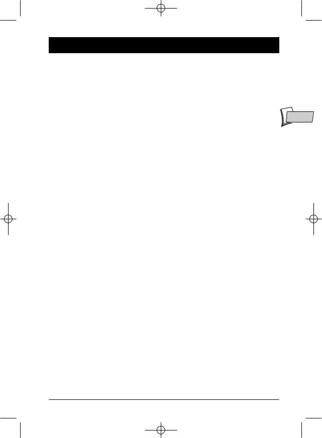
You will obtain optimal service operation of your Video Sender by correctly orienting the antenna (A). However, reflected signals or other signal degrading factors can affect good quality signal transmission. In this case, readjust antenna positions or slightly move the transmitter or receiver until you get crystal clear reception.
Transmitter / Receiver
(A)
off.on 


If no picture is obtained,
check that the transmitter and the receiver have not been installed in the reverse order (each unit corresponds either to the input or to the output of the Audio-Video signal). Check that they have been properly connected and that they are switched on (on position). Ensure that the channel selector is set to the same letter on both units.
If transmission is blurred or scrambled,
choose another channel but make sure that it is identical on both units.
Transmitter |
Receiver |
8
01_VS470_en 24/08/04 10:34 Page 9
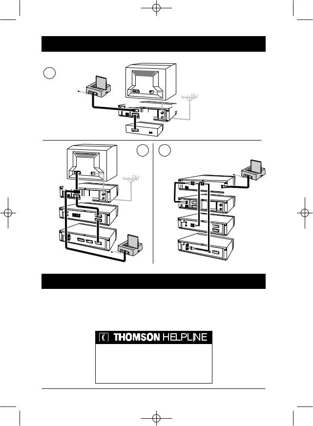
Relay of pictures from several units
If you have several equipment items (VCR player, satellite receiver, DVD player, etc.) in your main |
|
equipment room and want to transmit and receive audio and video signals to a second TV set, |
|
connect your equipment items as shown in the Diagrams on following pages. Usually, the units are |
|
connected in series, the last unit having a free scart connection that you can use for the |
|
connection of the transmitter. |
EN |
|
! These diagrams represent some connection possibilities the operation of which depends on the type of unit, its sockets and the signals it produces.There exist other connections that you might perhaps wish to try if diagrams 1 to 3 here are not satisfactory. If this is the case, ask your dealer for assistance.
! As a general rule, remember to switch off units not in use. Also, refer to the manufacturers’ instructions to see if there are any particularities regarding connection or use. Certain units may need to have their input scart connection “programmed”.
!In all cases the transmitter must be connected to a scart connection that produces an Audio-Video signal Out. Refer to the manufacturer’s instructions for confirmation of this.
9
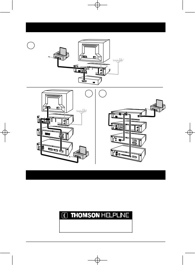
01_VS470_en 24/08/04 10:34 Page 10
General information on connections...
1 |
Transmitter |
|
TV1 |
|
|
|
|
|
|
|
|
AV1 |
V C R |
|
|
|
|
|
|
|
|
AV2 |
|
|
|
|
|
Satellite or Cable decoder |
|
|
|
|
(Canal+, Canal Sat,TPS, Premiere,Telepiu,Via Digital…) |
|
TV1 |
|
2 |
3 AUDIO |
Transmitter |
|
|
|
Audio amplifier |
|
AV1 |
|
|
|
|
VCR |
|
|
|
AV output |
|
AV2 |
|
|
VCR |
|
|
|
|
|
DVD |
|
|
|
|
DVD
Transmitter
SAT
SAT
Technical characteristics
Power supply: 12V DC (transmitter), 9V DC (receiver),
4 channels (A : 2.411 GHz - B : 2.434 GHz - C : 2.454 GHz - D : 2.473 GHz) Remote control return: 433,92 MHz
Transmitter power: 10 mW
You can contact THOMSON by dialling: 0871 712 1312 (For Great-Britain, all calls will be charged 0,10£ / mn) www.thomson-europe.com
10
02_VS470_fr 24/08/04 10:40 Page 1
Transmetteur vidéo sans fil
Précautions
Sécurité
•Les composants de cet appareil sont sensibles à la chaleur. La température maximale ambiante ne doit pas dépasser 35° Celsius.
•L’humidité des locaux où est placé l’appareil ne doit pas dépasser un taux hygrométrique de
85 %. Evitez de l’exposer à l’eau de pluie ou aux éclaboussures. Le passage d’une atmosphère |
FR |
froide à une ambiance chaude peut provoquer de la condensation. Laissez-la disparaître d’elle- |
|
même avant de remettre l’appareil en marche. |
|
•En cas d’absence prolongée, éteignez l’appareil avec l’interrupteur marche/arrêt. Même à l’arrêt, certains composants restent en contact avec le réseau électrique. Pour l’isoler complètement vous devez débrancher la fiche d’alimentation de la prise secteur.
•En cas d’orage, il est recommandé d’isoler l’appareil du réseau électrique afin de ne pas le soumettre à des surcharges électriques ou électromagnétiques qui peuvent l’endommager. A cette fin, laissez la fiche secteur accessible pour le débrancher.
•Débranchez immédiatement l’appareil si vous constatez qu’il dégage une odeur de brûlé ou de la fumée. En aucun cas vous ne devez ouvrir l’appareil vous-même, vous risquez l’électrocution.
Entretien
•Nettoyez l’appareil avec un chiffon doux et un détergent neutre. L’utilisation de solvants, de produits abrasifs ou de produits à base d’alcool risque d’endommager l’appareil.
Réglementation
•Cet appareil ne doit être installé qu'à l'intérieur d'un local. Son utilisation est restreinte aux transmissions radioélectriques privées. Le branchement à un réseau public ou indépendant ou à une antenne extérieure est interdit.
Cet appareil ne doit en aucun cas être utilisé à des fins commerciales. Il est uniquement prévu pour un usage domestique.
THOMSON dégage sa responsabilité en cas d’utilisation non conforme aux indications de cette notice.
1

02_VS470_fr 24/08/04 10:40 Page 2
Principes de fonctionnement
SALON CHAMBRE
Transmitter |
Receiver |
|
(Emetteur) |
(Récepteur) |
|
|
Télécommande du |
|
Magnétoscope, |
magnétoscope, récepteur |
|
satellite... ou télécommande |
||
Récepteur satellite, ... |
||
universelle. |
||
|
2
02_VS470_fr 24/08/04 10:40 Page 3
A quoi sert cet appareil ?
Le Video Sender VS 470 permet de diffuser un signal Audio-Video à partir de votre installation principale vers un second téléviseur installé dans une autre pièce et équipé d’une prise péritélévision (ou RCA/Cinch). L’installation principale est l’endroit où vous avez regroupé la plupart de vos appareils (téléviseur, magnétoscope, récepteur satellite, lecteur DVD, ...).Vous pourrez commander les appareils depuis la pièce où se trouve le second téléviseur à l’aide de leurs télécommandes, ou avec une télécommande universelle.
La diffusion de musique est possible si vous raccordez l’émetteur à une source (AUDIO OUT) et le récepteur à un amplificateur (AUDIO IN) dans une autre pièce.
Si vous possédez un moniteur plasma ou un projecteur vidéo Thomson, le Video Sender vous |
FR |
facilitera leur implantation à l’endroit désiré grâce à l’élimination des problèmes liés à la longueur |
|
des câbles de connexions. |
|
Camescope
Amplificateur A/V
Magnétoscope
DVD
Lecteur Video-disc
Moniteur plasma
TV
Récepteur et décodeur |
Vidéo projecteur |
Satellite/Câble |
|
3
02_VS470_fr 24/08/04 10:40 Page 4
Installation de l’émetteur
Réferez-vous au schéma global d’installation situé en début de notice, dans la couverture, ainsi qu’au schéma de la page suivante.
1.Placez l’émetteur (1) à proximité de l’appareil (magnétoscope, lecteur DVD…) dont vous souhaitez diffuser les images et le son et raccordez-le à l’aide du cordon (2). Raccordez la fiche péritélévision à une prise du magnétoscope ou du lecteur DVD (AV1).
Procurez-vous un cordon SCART-Péritélévision (non fourni) et raccordez le téléviseur à l’adaptateur (2) déjà branché au magnétoscope ou lecteur DVD (voir repère * de la page 5).
2.Déployez l’antenne de l’émetteur (1) avec précaution et orientez-la en direction de la pièce du second téléviseur (TV2). Mettez en marche (position on) l’émetteur à l’aide du bouton off/on situé sur le coté. Placez le sélecteur de canal de l’émetteur (et du récepteur) sur la même position (même lettre).
3.Installez le cordon (4) en suivant ces étapes :
-raccordez la fiche jack dans la prise IR ext,
-déroulez le cordon et placez une cellule à proximité de la fenêtre infrarouge de l'appareil à commander,
-après l’installation du récepteur (voir page 6 et 7), demandez à une personne d'utiliser la télécommande de l'appareil à commander depuis la pièce où se trouve le second téléviseur (TV2),
-en déplaçant la cellule devant l'appareil à commander vous pourrez déterminer l'emplacement qui permet sa commande depuis l'autre pièce.Vous devrez y coller la cellule. Généralement il s'agit d'une zone transparente plus ou moins grande située en façade.
4.Enlevez le papier de protection de la partie auto-collante de la cellule infrarouge du cordon (4) et collez-la sur la fenêtre infrarouge de l’appareil à télécommander. Le cordon est équipé de 3 cellules afin de vous permettre de diffuser les images et le son de 3 appareils connectés au téléviseur (TV1) (voir schéma 2 de la page 10).
5.Branchez l’adaptateur d’alimentation (3) à l’émetteur et à une prise secteur 220/240V ~ 50 Hz.
Note : Les adaptateurs pour l’alimentation de l’émetteur et du récepteur sont différents. Celui prévu pour l’émetteur est un modèle 12V-200mA.
4

02_VS470_fr 24/08/04 10:40 Page 5
Installation de l’émetteur
Installation de l’émetteur :
Verticalement en utilisant le support ou horizontalement sans le support.
Note : La fenêtre IR doit être dirigée vers l’utilisateur.
Antenne :
Selon la distance entre l’émetteur et le récepteur, déployez l’antenne et orientez-la de façon à ce |
FR |
||||||
que les inscriptions (WIRELESS) soient dirigées l’une vers l’autre. Si l’émetteur et le récepteur sont |
|
||||||
assez proches, il ne sera peut-être pas nécessaire de déployer les antennes. |
|
||||||
|
|
|
|
|
|
|
|
|
|
|
|
|
|
|
|
TV2
TV1
220/240V ~ 50 Hz
ROYAUME-
UNI -
IRLANDE
1 3
2
EUROPE CONTINENTALE
*
4
5

02_VS470_fr 24/08/04 10:40 Page 6
Installation du récepteur
1.Placez le récepteur (5) sur, ou à proximité du second téléviseur.
2.Raccordez le récepteur (5) au second téléviseur à l’aide du cordon (6) en suivant les mêmes recommandations que pour l’émetteur.
3.Déployez l’antenne du récepteur (5) et orientez-la en direction du téléviseur principal (TV1).
4.Branchez l’adaptateur d’alimentation (9V, 400mA) (7) au récepteur et à une prise secteur 220/240V ~ 50 Hz.
!L’ANTENNE permet la diffusion du signal Audio-Video sur une portée maximum de 80 mètres en champ libre. A l’intérieur d’une habitation cette portée est inférieure et dépend des matériaux que les ondes auront à franchir.
!L’ANTENNE SOUPLE permet la commande de l’appareil dont vous souhaitez voir les images à partir de la pièce où se trouve le second téléviseur (TV2).
!L’ALIMENTATION de l’émetteur (1) possède une prise différente de celle de l’alimentation du récepteur (7).
TV2
5 7
220/240V ~ 50 Hz
ROYAUME-
UNI -
IRLANDE
EUROPE
CONTINENTALE
Receiver
Receiver
6
VIDEO OUT |
L AUDIO OUT R |
DC 9V |
6
02_VS470_fr 24/08/04 10:40 Page 7
Utilisation
1.Mettez en marche l’émetteur (1) et le récepteur (5) en plaçant leurs boutons off/on sur la position on.
2.Assurez-vous que l’émetteur et le récepteur soient bien sur le même canal en vérifiant la position des sélecteurs sous le boîtier ou sous l’antenne. Ils doivent être placés sur le même canal (même lettre).
3.Mettez en marche vos appareils (téléviseurs, magnétoscopes, ...) dans les 2 pièces.
4.A l’aide de la télécommande de l’appareil dont vous voulez voir les images, et de la pièce où se
trouve le second téléviseur (TV2), sélectionnez les chaînes ou les fonctions de lecture (ou |
FR |
autres) selon l’appareil que vous commandez. |
|
Receiver (Récepteur)
Prenez soin de diriger la télécommande vers la fenêtre infrarouge du récepteur (5)
Quelques particularités de fonctionnement :
•Pas d’image sur TV2 ? Si vous n’obtenez pas l’image souhaitée sur le second téléviseur TV2, sélectionnez la prise AV, à laquelle est raccordée le récepteur (5), à l’aide de la télécommande du téléviseur.
•Décodeur (Canal +,TPS…) sur TV2 ? Pour être visible sur le second téléviseur (TV2), l’image d’un décodeur doit passer par un magnétoscope, mis en marche, en mode AV2 ou sur le n° de
chaîne attribué à la chaîne codée. (Reportez-vous aux notices des appareils correspondants).
•Utilisation d’un moniteur ? Si votre second téléviseur ne possède pas de raccordement à une antenne extérieure (réception hertzienne), ou si c’est un moniteur, vous pourrez voir les chaînes en sélectionnant celles du magnétoscope, à partir de la pièce du second téléviseur et à l’aide de la télécommande du magnétoscope.
•L'image est brouillée ? Le fonctionnement de certains appareils (four à micro-ondes, téléphone numérique DECT, enceintes acoustiques non blindées,etc ...) peut perturber la transmission du signal. Veillez à les tenir éloignés de l'émetteur et du récepteur ou éteignez-les.
7
02_VS470_fr 24/08/04 10:40 Page 8
Amélioration de l’image et du son
Vous obtiendrez un fonctionnement optimal de votre Video Sender en orientant l’antenne (A). Toutefois, certaines réflexions ou autres effets parasites peuvent affecter la bonne transmission du signal. Il suffira alors, soit de réajuster la position de l’antenne soit de déplacer légèrement l'émetteur ou le récepteur jusqu’à l’obtention d’une parfaite réception.
Transmitter / Receiver (Emetteur) / (Récepteur)
(A)
off.on 


Si vous n’obtenez aucune image,
vérifiez que l'émetteur et le récepteur n’aient pas été inversés (chaque boîtier correspond soit à l’entrée soit à la sortie du signal Audio-Video).Vérifiez qu’ils sont bien connectés et en marche (position on).Assurez-vous que le sélecteur des canaux est bien positionné sur la même lettre.
Si la transmission n’est pas claire ou brouillée,
choisissez un autre canal en veillant à ce qu’ils soient identiques sur les 2 boîtiers.
Transmitter |
Receiver |
(Emetteur) |
(Récepteur) |
8
02_VS470_fr 24/08/04 10:40 Page 9
Diffusion des images de plusieurs appareils
Si dans votre installation principale, vous possédez plusieurs appareils (magnétoscope, récepteur satellite, lecteur DVD...) dont vous souhaitez diffuser les images et le son vers un second téléviseur, raccordez-les en suivant les indications des schémas proposés en page suivante. En général les appareils sont raccordés en série, le dernier appareil disposant d’une prise péritélévision de libre que vous pourrez utiliser pour raccorder l’émetteur.
! Ces schémas représentent quelques possibilités de raccordements dont le fonctionnement dépend des |
|
appareils, de leurs prises et des signaux qu’ils fournissent. Il existe donc d’autres raccordements que vous |
FR |
serez peut-être amenés à essayer si les schémas 1 à 3 proposés ne vous satisfont pas. Dans ce cas |
|
faites-vous aider par votre revendeur. |
|
!De façon générale, pensez à éteindre les appareils non utilisés. Consultez également les notices des constructeurs pour connaître d’éventuelles particularités de branchement ou d’utilisation. Certains appareils peuvent nécessiter une “programmation” de la prise péritélévision du signal entrant.
!Dans tous les cas l’émetteur doit être branché sur une prise péritélévision fournissant un signal AudioVideo Out. Reportez-vous à la notice du constructeur pour le vérifier.
9
02_VS470_fr 24/08/04 10:40 Page 10
A propos des raccordements …
|
Transmitter |
|
|
TV1 |
|
1 |
(Emetteur) |
|
|
|
|
|
|
|
|
|
|
|
|
AV1 |
|
V C R |
|
|
|
|
|
|
|
|
|
AV2 |
|
|
|
|
|
|
Décodeur satellite / câble |
|
|
|
|
|
(Canal+, Canal Sat,TPS, Premiere,Telepiu,Via Digital…) |
||
TV1 |
|
2 |
3 |
AUDIO |
Transmitter |
|
|
|
|
|
(Emetteur) |
|
|
|
|
Amplificateur Audio |
|
AV1 |
|
|
|
|
|
VCR |
|
|
|
|
Sortie AV |
|
AV2 |
|
|
|
VCR |
|
|
|
|
|
|
DVD |
|
|
|
|
|
DVD
Transmitter
(Emetteur)
SAT
SAT
Caractéristiques techniques
Alimentation : 12V DC (émetteur), 9V DC (récepteur),
4 canaux (A : 2.411 GHz - B : 2.434 GHz - C : 2.454 GHz - D : 2.473 GHz) Retour télécommande : 433,92 MHz
Puissance de l’émetteur : 10 mW
Votre Contact THOMSON :
pour la France : 0 826 820 456 (0,15e / mn) pour la Suisse : 0 900 905 950 (0,18chf / mn) pour la Belgique : 070 300 014
(coût d’une communication locale) www.thomson-europe.com
10
03_VS470_de 24/08/04 10:41 Page 1
Video-Signal-Sender/-Empfänger
Vorsichtsmaßnahmen
Sicherheit
•Die Bauteile dieses Geräts sind wärmeempfindlich. Die maximale Umgebungstemperatur darf 35°C nicht überschreiten.
•Die Luftfeuchtigkeit im Aufstellungsraum des Geräts darf einen Feuchtigkeitsgehalt von 85% nicht übersteigen. Sollten Sie Ihr Gerät im Freien betreiben, schützen Sie es unbedingt vor Regen und Spritzwasser. Der Transport des Geräts aus einer kalten Umgebung in einen warmen Raum kann Kondensation hervorrufen. Warten Sie, bis diese von allein abtrocknet, bevor Sie das Gerät in Betrieb nehmen.
• Bei längerer Abwesenheit das Gerät mit dem Netzschalter abschalten. Selbst wenn der DE Netzschalter sich in der Aus-Stellung befindet, ist das Gerät nicht vollständig vom Netz getrennt.
Um das Gerät vollständig stromlos zu machen, muß der Netzstecker gezogen werden.
•Bei Gewitter wird empfohlen, das Gerät vom Netz zu trennen, damit es nicht elektrischen bzw. elektromagnetischen Einwirkungen ausgesetzt wird, die es beschädigen können. Deshalb muß der Netzstecker stets zugänglich sein, damit Sie ihn jederzeit aus der Steckdose ziehen können.
•Sofort den Netzstecker ziehen, wenn Sie bemerken, daß das Gerät einen Verbrennungsgeruch oder Rauch verströmt. Öffnen Sie das Gerät auf keinen Fall selbst, Sie setzen sich sonst der Gefahr lebensgefährlicher elektrischer Schläge aus.
Pflege
•Das Gerät mit einem weichen Lappen und einem neutralen Putzmittel reinigen.Verwenden Sie keine Lösungsmittel, Scheuermittel und Reinigungsmittel auf Alkoholbasis, da diese Ihr Gerät beschädigen könnten.
Gesetzliche Vorschriften
•Dieses Gerät ist zum Betrieb in geschlossenen Räumen bestimmt. Seine Benutzung ist auf die private Funkübertragung beschränkt. Der Anschluß an ein öffentliches bzw. privates Netz oder an eine Außenantenne ist untersagt.
Dieses Gerät darf auf keinen Fall zu gewerblichen Zwecken verwendet werden, sondern dient ausschließlich dem Heimgebrauch.
Der nichtbestimmungsgemäße Gebrauch bzw. die Nichtbeachtung der Anweisungen dieser Bedienungsanleitung erfolgt auf eigene Gefahr, unter Ausschluß aller Rechtsansprüche gegenüber THOMSON.
1

03_VS470_de 24/08/04 10:41 Page 2
Funktionsprinzipien
WOHNZIMMER SCHLAFZIMMER
Transmitter |
Receiver |
|
(Sender) |
(Empfänger) |
|
|
Fernbedienung des |
|
|
Videorecorders, |
|
Videorecorder, |
Satellitenempfängers |
|
usw. – oder |
||
Satellitenempfänger usw. |
||
Universalfernbedienung. |
||
|
2
03_VS470_de 24/08/04 10:41 Page 3
Wozu dient dieses Gerät?
Der Video Sender VS 470 erlaubt die Übertragung eines Audio-Video-Signals über Ihre Hauptanlage an einen zweiten, in einem anderen Raum aufgestellten und mit einer SCART-Buchse (oder RCA/Cinch) ausgestatteten Fernseher. Die Hauptanlage befindet sich dort, wo Sie den größten Teil Ihrer Geräte (Fernseher, Videorecorder, Satellitenempfänger, DVD-Spieler usw.) aufgestellt haben. Sie können diese Geräte vom Raus aus, in dem sich der Zweitfernseher befindet, steuern, entweder mit den Fernbedienungen Ihrer Geräte, oder mit einer Universalfernbedienung.
Die Musikübertragung ist möglich, wenn Sie den Sender an eine Quelle (AUDIO OUT) und den Empfänger an einen Verstärker (AUDIO IN) in einem anderen Raum anschließen.
Wenn Sie einen Plasma-Bildschirm oder einen Thomson-Videoprojektor besitzen, erleichtert der Video Sender Ihnen deren Aufstellung am gewünschten Ort, denn es gibt keine durch lange Anschlusskabel hervorgerufene Probleme.
DE
Camcorder
A-V-Verstärker
Videorecorder
DVD-Spieler
Video-disc-Spieler
Plasma-Bildschirm
Fernseher
Satellitenund Videoprojektor
Kabelempfänger / -decoder
3
03_VS470_de 24/08/04 10:41 Page 4
Inbetriebnahme des Senders
Es wird auf das Gesamtschema der Anlage am Anfang der Anleitung im Umschlag sowie auf das Schema auf der folgenden Seite verwiesen.
1.Sender (1) in der Nähe des Gerätes (Videorecorder, DVD-Player …), dessen Bilder und Ton Sie übertragen wollen, anordnen und mit Hilfe der Schnur (2) anschließen. Peritelevision-Stecker an eine Buchse des Videorecorders oder des DVD-Players (AV1) anschließen.
Beschaffen Sie sich eine SCART-Peritelevision-Anschlussschnur (nicht mitgeliefert) und schließen das Fernsehgerät an den bereits an den Videorecorder oder den DVD-Player angeschlossenen Adapter (2) an (siehe Markierung * auf Seite 5).
2.Antenne des Senders (1) vorsichtig ausfahren und auf den Raum ausrichten, in dem sich das zweite Fernsehgerät (TV2) befindet. Sender mit dem seitlich befindlichen Schaltknopf off/on einschalten. Kanalwähler des Senders (und Empfängers) in die gleiche Position stellen (gleicher Buchstabe).
3.Zum Anschließen des Kabels (4) die folgenden Schritte ausführen:
-Den Klinkenstecker in die Buchse IR ext stecken,
-Das Kabel abwickeln und eine Zelle in der Nähe des Infrarotfensters des zu steuernden Geräts (Videorecorder oder anderes Gerät) positionieren,
-Nach Installation des Empfängers (siehe Seiten 6 und 7) eine Person bitten, die Fernbedienung des zu bedienenden Gerätes von dem Raum aus, in dem sich das zweite Fernsehgerät (TV2) befindet, zu betätigen,
-Durch Verschieben der Zelle vor dem zu steuernden Gerät können Sie den Anbringungsort bestimmen, der das Steuern vom anderen Raum aus erlaubt. Kleben Sie die Zelle an der ermittelten günstigsten Stelle an. Es handelt sich in der Regel um einen mehr oder weniger großen durchsichtigen Bereich auf der Vorderseite.
4.Schutzpapier des Selbstklebeteils der Infrarotzelle der Schnur (4) entfernen und auf das Infrarotfenster des fernzubedienenden Geräts kleben. Die Schnur ist mit drei Zellen ausgestattet, um es Ihnen zu gestatten, Bilder und Ton von drei an das Fernsehgerät (TV1) angeschlossenen Geräten zu übertragen (siehe Schema 2 auf Seite 10).
5.Netzgerät (3) an den Sender und an eine Netzsteckdose 220/240V ~ 50 Hz anschließen.
Anmerkung: Die Netzgeräte für Sender und Empfänger sind verschieden. Bei dem für den Sender vorgesehenen Gerät handelt es sich um ein Modell 12V-200mA.
4
03_VS470_de 24/08/04 10:41 Page 5
Inbetriebnahme des Senders
Installation des Senders:
Vertikal, indem Sie den Halter verwenden, oder horizontal ohne Halter.
Anmerkung: Das Infrarotfenster muss auf den Benutzer gerichtet sein.
Antenne:
Je nach Entfernung zwischen Sender und Empfänger Antenne ausfahren und so ausrichten, dass die Aufschriften (WIRELESS) aufeinander gerichtet sind.Wenn Sender und Empfänger sich ziemlich nahe beieinander befinden, ist es vielleicht nicht nötig, die Antennen auszufahren.
DE
TV2
TV1
220/240V ~ 50 Hz
Großbritannien,
Irland
1 3
2
Kontinentaleuropa
*
4
5
03_VS470_de 24/08/04 10:41 Page 6
Inbetriebnahme des Empfängers
1.Den Empfänger (5) auf dem bzw. in der Nähe des zweiten Fernsehers aufstellen.
2.Den Empfänger (5) mit dem Kabel (6) an den zweiten Fernseher anschließen, indem Sie nach den selben Anweisungen wie für den Sender vorgehen.
3.Antenne des Empfängers (5) ausfahren und auf das Hauptfernsehgerät (TV1) richten.
4.Netzgerät (9V, 400mA) (7) an den Empfänger und an eine Netzsteckdose 220/240V ~ 50 Hz anschließen.
!DIE ANTENNE ermöglicht die Übertragung des Audio/Video-Signals über eine maximale Reichweite von 80 Metern im freien Feld. Innerhalb eines Wohnhauses ist diese Reichweite geringer und hängt von den Baustoffen ab, welche die Wellen zu durchdringen haben.
!DIE FLEXIBLE ANTENNE dient zur Steuerung des Geräts, dessen Bilder Sie im Aufstellungsraum des zweiten Fernsehers (TV2) betrachten möchten.
!DAS NETZGERÄT des Senders (1) ist mit einer anderen Buchse als das Netzgerät des Empfängers (7) ausgestattet.
TV2
220/240V ~ 50 Hz
Großbritannien,
Irland
Kontinentaleuropa
5 7
Receiver
Receiver
6
VIDEO OUT |
L AUDIO OUT R |
DC 9V |
6
03_VS470_de 24/08/04 10:41 Page 7
Benutzung
1.Den Sender (1) und den Empfänger (5) einschalten, indem Sie deren off/on-Schalter auf on schalten.
2.Sich vergewissern, dass Sender und Empfänger sich auf dem gleichen Kanal befinden, indem Sie die Position der Wählschalter unter dem Gehäuse oder unter der Antenne überprüfen. Beide Wahlschalter müssen auf den selben Kanal eingestellt sein (d.h. auf den selben Buchstaben).
3.Schalten Sie Ihre Geräte (Fernseher,Videorecorder usw.) in den beiden Räumen ein.
4.Im Aufstellungsraum des zweiten Fernsehers (TV2) mit der Fernbedienung des Geräts, dessen Bilder Sie sehen möchten, das gewünschte Programm bzw. die Wiedergabefunktion (oder eine andere Funktion) wählen bzw. aktivieren, je nach dem zu steuernden Gerät.
DE
Receiver (Empfänger)
Denken Sie daran, die Fernbedienung stets auf das Infrarotfenster des Empfängers (5) zu richten
Einige Besonderheiten des Betriebs:
•TV2 hat kein Bild? Wenn das gewünschte Bild nicht vom zweiten Fernseher TV2 angezeigt wird, müssen Sie die AV-Buchse, an die der Empfänger (5) angeschlossen ist, mit der Fernbedienung des Fernsehgeräts wählen.
•Decoder (Canal +,TPS…) an TV2? Damit es auf dem zweiten Fernseher (TV2) sichtbar ist, muss das Bild eines Decoders über einen Videorecorder, der im Modus AV2 eingeschaltet ist, oder über das dem codierten Programm zugeordneten Programm gehen.
•Einsatz eines Monitors? Wenn Ihr zweiter Fernseher nicht an eine Außenantenne (Funkfernsehempfang) angeschlossen ist oder wenn es sich um einen Monitor handelt, können Sie die Fernsehprogramme sehen, indem Sie im Ausstellungsraum des zweiten Fernsehers bzw. Monitors die
vom Videorecorder empfangenen Programme mit dessen Fernbedienung wählen.
•Bildstörungen? Der Betrieb einiger Geräte (Mikrowellengerät, DECT-Digitaltelefon, nicht abgeschirmte Lautsprecherboxen usw.) kann die Signalübertragung stören. Denken Sie daran, diese Geräte in möglichst großer Entfernung vom Sender und Empfänger aufzustellen oder auszuschalten.
7
 Loading...