


TDSO3150
Telefunken TDSO3150, TDSO3160, TDSY3160, TDSG3150, TDSG3160 Datasheet
...
TDS.31..
Vishay Telefunken
1 (9)
Rev. A1, 02-Jun-99
www.vishay .de • FaxBack +1-408-970-5600Document Number 83125
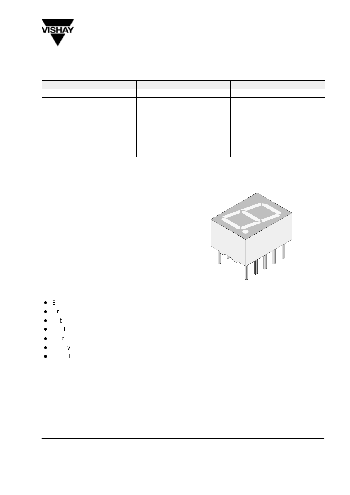
10 mm Seven Segment Display
Color Type Circuitry
Red TDSR315. Common anode
Red TDSR316. Common cathode
Orange red TDSO315. Common anode
Orange red TDSO316. Common cathode
Yellow TDSY315. Common anode
Yellow TDSY316. Common cathode
Green TDSG315. Common anode
Green TDSG316. Common cathode
Description
The TDS.31.. series are 10 mm character seven
segment LED displays in a very compact package.
The displays are designed for a viewing distance up to
6 meters and available in four bright colors. The grey
package surface and the evenly lighted untinted
segments provide an optimum on-off contrast.
All displays are categorized in luminous intensity
groups. That allows users to assemble displays with
uniform appearence.
Typical applications include instruments, panel
meters, point-of-sale terminals and household
equipment.
Features
D
Evenly lighted segments
D
Grey package surface
D
Untinted segments
D
Luminous intensity categorized
D
Yellow and green categorized for color
D
Wide viewing angle
D
Suitable for DC and high peak current
96 11507
Applications
Panel meters
Test- and measure- equipment
Point-of-sale terminals
Control units
TDS.31..
Vishay Telefunken
2 (9)
Rev. A1, 02-Jun-99
www.vishay .de • FaxBack +1-408-970-5600 Document Number 83125
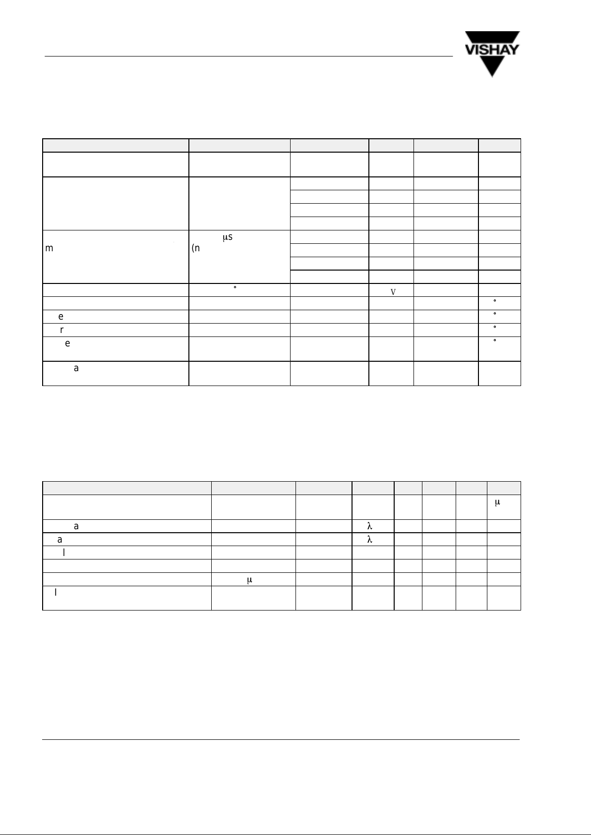
Absolute Maximum Ratings
T
amb
= 25°C, unless otherwise specified
TDSR315. /TDSR316. , TDSO315. /TDSO316. , TDSY315. /TDSY316. , TDSG315. /TDSG316. , /
Parameter Test Conditions Type Symbol Value Unit
Reverse voltage per
segment or DP
V
R
6 V
DC forward current per TDSR315./316. I
F
30 mA
segment or DP
TDSO315./316. I
F
20 mA
TDSY315./316. I
F
20 mA
TDSG315./316. I
F
20 mA
Surge forward current per seg- tp ≤ 10 ms TDSR315./316. I
FSM
0.5 A
gg
ment or DP
p
m
(non repetitive)
TDSO315./316. I
FSM
0.15 A
TDSY315./316. I
FSM
0.15 A
TDSG315./316. I
FSM
0.15 A
Power dissipation T
amb
≤ 45°C P
V
480 mW
Junction temperature T
j
100
°
C
Operating temperature range T
amb
–40 to + 85
°
C
Storage temperature range T
stg
–40 to + 85
°
C
Soldering temperature t ≤ 3 sec, 2mm
below seating plane
T
sd
260
°
C
Thermal resistance LED
junction/ambient
R
thJA
120 K/W
Optical and Electrical Characteristics
T
amb
= 25°C, unless otherwise specified
Red (TDSR315. , TDSR316. )
Parameter Test Conditions Type Symbol Min Typ Max Unit
Luminous intensity per segment
(digit average)
1)
IF = 10 mA TDSR
3150/3160
I
V
180
m
cd
Dominant wavelength IF = 10 mA
l
d
655 nm
Peak wavelength IF = 10 mA
l
p
660 nm
Angle of half intensity IF = 10 mA ϕ ±50 deg
Forward voltage per segment or DP IF = 20 mA V
F
1.6 2 V
Reverse voltage per segment or DP IR = 10 mA V
R
6 15 V
1)
I
Vmin
and IV groups are mean values of
segments a to g
TDS.31..
Vishay Telefunken
3 (9)
Rev. A1, 02-Jun-99
www.vishay .de • FaxBack +1-408-970-5600Document Number 83125
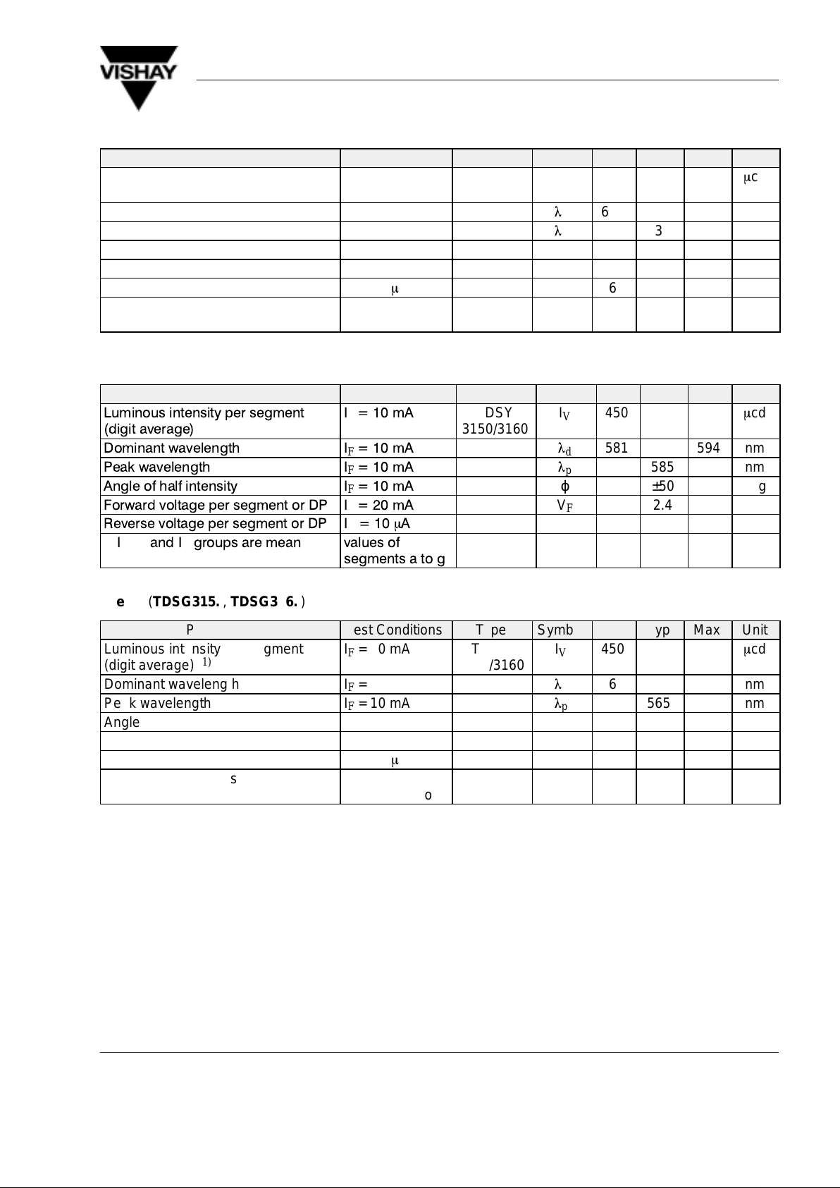
Orange red (TDSO315. , TDSO316. )
Parameter Test Conditions Type Symbol Min Typ Max Unit
Luminous intensity per segment
(digit average)
1)
IF = 10 mA TDSO
3150/3160
I
V
450
m
cd
Dominant wavelength IF = 10 mA
l
d
612 625 nm
Peak wavelength IF = 10 mA
l
p
630 nm
Angle of half intensity IF = 10 mA ϕ ±50 deg
Forward voltage per segment or DP IF = 20 mA V
F
2 3 V
Reverse voltage per segment or DP IR = 10 mA V
R
6 15 V
1)
I
Vmin
and IV groups are mean values of
segments a to g
Yellow (TDSY315. , TDSY316. )
Parameter Test Conditions Type Symbol Min Typ Max Unit
Luminous intensity per segment
(digit average)
1)
IF=10mA
TDSY
3150/3160
I
V
450
m
cd
Dominant wavelength IF=10mA
l
d
581 594 nm
Peak wavelength IF=10mA
l
p
585 nm
Angle of half intensity IF=10mA
ϕ ±50 deg
Forward voltage per segment or DP IF=20mA
V
F
2.4 3 V
Reverse voltage per segment or DP IR=10mA
V
R
6 15 V
1)
I
Vmin
and IVgroups are mean values of
segments a to g
Green (TDSG315. , TDSG316. )
Parameter Test Conditions Type Symbol Min Typ Max Unit
Luminous intensity per segment
(digit average)
1)
IF = 10 mA TDSG
3150/3160
I
V
450
m
cd
Dominant wavelength IF = 10 mA
l
d
562 575 nm
Peak wavelength IF = 10 mA
l
p
565 nm
Angle of half intensity IF = 10 mA ϕ ±50 deg
Forward voltage per segment or DP IF = 20 mA V
F
2.4 3 V
Reverse voltage per segment or DP IR = 10 mA V
R
6 15 V
1)
I
Vmin
and IV groups are mean values of
segments a to g
 Loading...