


OPERATOR'S
MANUAL
Model 811, 813, 819, 821 Series
Auto Lift Gas Grills
Original Operating Instructions
073625-M
9/15/10 (Original Publication)
(Updated 9/4/14)

Complete this page for quick reference when service is required:
Taylor Distributor:
Address:
Phone:
Service:
Parts:
Date of Installation:
Information found on data plate:
Model Number:
Serial Number:
Electrical Specs: Voltage |
|
Cycle |
||||||
|
Phase |
|
|
|
|
|
||
Maximum Fuse Size: |
|
|
|
|
Amps |
|||
Minimum Wire Ampacity: |
|
|
|
|
Amps |
|||
Part Number: |
|
|
|
|
|
|||
E 2010 Carrier Commercial Refrigeration, Inc. 073625-M
Any unauthorized reproduction, disclosure, or distribution of copies by any person of any portion of this work may be a violation of Copyright Law of the United States of America and other countries, could result in the awarding of Statutory Damages of up to $250,000 (17 USC 504) for infringement, and may result in further civil and criminal penalties. All rights reserved.
Taylor Company
a division of Carrier Commercial Refrigeration, Inc. 750 N. Blackhawk Blvd.
Rockton, IL 61072

Table of Contents
Section 1 |
To the Installer . . . . . . . . . . . . . . . . . . . . . . . . . . . . . . . . . . . . . . . . . . . . |
1 |
Installer Safety . . . . . . . . . . . . . . . . . . . . . . . . . . . . . . . . . . . . . . . . . . . . . . . . . . . . . . . . |
1 |
|
Site Preparation . . . . . . . . . . . . . . . . . . . . . . . . . . . . . . . . . . . . . . . . . . . . . . . . . . . . . . . |
1 |
|
Electrical Connections . . . . . . . . . . . . . . . . . . . . . . . . . . . . . . . . . . . . . . . . . . . . . . . . . |
1 |
|
Installation |
. . . . . . . . . . . . . . . . . . . . . . . . . . . . . . . . . . . . . . . . . . . . . . . . . . . . . . . . . . . |
2 |
Section 2 |
To the Operator . . . . . . . . . . . . . . . . . . . . . . . . . . . . . . . . . . . . . . . . . . . |
3 |
Section 3 |
Safety . . . . . . . . . . . . . . . . . . . . . . . . . . . . . . . . . . . . . . . . . . . . . . . . . . . . |
4 |
Section 4 |
Operator Parts Identification . . . . . . . . . . . . . . . . . . . . . . . . . . . . . . . |
7 |
C811 Exploded View . . . . . . . . . . . . . . . . . . . . . . . . . . . . . . . . . . . . . . . . . . . . . . . . . . |
7 |
|
L811 Exploded View . . . . . . . . . . . . . . . . . . . . . . . . . . . . . . . . . . . . . . . . . . . . . . . . . . . |
8 |
|
C813 Exploded View . . . . . . . . . . . . . . . . . . . . . . . . . . . . . . . . . . . . . . . . . . . . . . . . . . |
9 |
|
L813 Exploded View . . . . . . . . . . . . . . . . . . . . . . . . . . . . . . . . . . . . . . . . . . . . . . . . . . . |
10 |
|
C819 Exploded View . . . . . . . . . . . . . . . . . . . . . . . . . . . . . . . . . . . . . . . . . . . . . . . . . . |
11 |
|
L819 Exploded View . . . . . . . . . . . . . . . . . . . . . . . . . . . . . . . . . . . . . . . . . . . . . . . . . . . |
12 |
|
C821 Exploded View . . . . . . . . . . . . . . . . . . . . . . . . . . . . . . . . . . . . . . . . . . . . . . . . . . |
13 |
|
L821 Exploded View . . . . . . . . . . . . . . . . . . . . . . . . . . . . . . . . . . . . . . . . . . . . . . . . . . . |
14 |
|
Accessories |
. . . . . . . . . . . . . . . . . . . . . . . . . . . . . . . . . . . . . . . . . . . . . . . . . . . . . . . . . . |
15 |
Section 5 |
Important: To the Operator . . . . . . . . . . . . . . . . . . . . . . . . . . . . . . . . . |
16 |
Model 811, 813, 819, 821 Series |
Table of Contents |
|
|

Table of Contents - Page 2
Section 6 |
Operating Procedures . . . . . . . . . . . . . . . . . . . . . . . . . . . . . . . . . . . . . |
17 |
Daily Opening Procedures . . . . . . . . . . . . . . . . . . . . . . . . . . . . . . . . . . . . . . . . . . . . . . |
17 |
|
Loading Store Menu Items To USB . . . . . . . . . . . . . . . . . . . . . . . . . . . . . . . . . . . . . . |
23 |
|
Loading Menu Items From USB . . . . . . . . . . . . . . . . . . . . . . . . . . . . . . . . . . . . . . . . . |
24 |
|
Operating Procedures . . . . . . . . . . . . . . . . . . . . . . . . . . . . . . . . . . . . . . . . . . . . . . . . . |
27 |
|
Daily Cleaning Procedures . . . . . . . . . . . . . . . . . . . . . . . . . . . . . . . . . . . . . . . . . . . . . |
29 |
|
Section 7 |
Troubleshooting Guide . . . . . . . . . . . . . . . . . . . . . . . . . . . . . . . . . . . . |
38 |
Section 8 |
Limited Warranty on Equipment . . . . . . . . . . . . . . . . . . . . . . . . . . . . |
43 |
Section 9 |
Limited Warranty on Parts . . . . . . . . . . . . . . . . . . . . . . . . . . . . . . . . . |
46 |
Wiring Diagrams . . . . . . . . . . . . . . . . . . . . . . . . . . . . . . . . . . . . . . . . . . . . . . . . . . . . . . |
49 |
|
Note: Continuing research results in steady improvements; therefore, information in this manual is subject to change without notice.
Note: Only instructions originating from the factory or its authorized translation representative(s) are considered to be the original set of instructions.
E 2010 Carrier Commercial Refrigeration, Inc. (Original Publication) (Updated August, 2014)
073625-M
Any unauthorized reproduction, disclosure, or distribution of copies by any person of any portion of this work may be a violation of Copyright Law of the United States of America and other countries, could result in the awarding of Statutory Damages of up to $250,000 (17 USC 504) for infringement, and may result in further civil and criminal penalties.
All rights reserved.
Taylor Company
a division of Carrier Commercial Refrigeration, Inc. 750 N. Blackhawk Blvd.
Rockton, IL 61072
Table of Contents |
Model 811, 813, 819, 821 Series |
|
|

Section 1 |
To the Installer |
|
|
The following information has been included in the manual as safety and regulatory guidelines. For complete installation instructions, please see the Installation Checklist.
 This unit has many sharp edges that can cause severe injuries.
Installer Safety
 In all areas of the world, equipment should be installed in accordance with existing local codes. Please contact your local authorities if you have any questions.
Care should be taken to ensure that all basic safety practices are followed during the installation and servicing activities related to the installation and service of Taylor equipment.
SOnly Taylor authorized service personnel should perform installation and repairs on the equipment.
SAuthorized service personnel should consult OSHA Standard 29CFRI910.147 or the applicable code of the local area for the industry standards on lockout/tagout procedures before beginning any installation or repairs.
SAuthorized service personnel must ensure that the proper PPE is available and worn when required during installation and service.
SAuthorized service personnel must remove all metal jewelry, rings, and watches before working on electrical equipment.
 The main power supply(s) to the equipment must be disconnected prior to performing any repairs. Failure to follow this instruction may result in personal injury or death from electrical shock or hazardous moving parts as well as poor performance or damage to the equipment.
Note: All repairs must be performed by an authorized Taylor Service Technician.
Site Preparation
Review the area where the unit will be installed before uncrating the unit. Make sure all possible hazards to the user or equipment have been addressed.
Electrical Connections
The grill is supplied with one power cord. Check the data plate on the grill for voltage, cycle, phase and electrical specifications.
For proper power connections, refer to the wiring diagram provided inside the left side panel, attached to the gas manifold assembly. The power connection is located behind the access line cover on the front of the grill.
In the United States, this equipment is intended to be installed in accordance with the National Electrical Code (NEC), ANSI/NFPA 70-1987. The purpose of the NEC code is the practical safeguarding of persons and property from hazards arising from the use of electricity. This code contains provisions considered necessary for safety. Compliance therewith and proper maintenance will result in an installation essentially free from hazard!
In all other areas of the world, equipment should be installed in accordance with the existing local codes. Please contact your local authorities.
The Proper Wire Size and Branch Circuit Overcurrent Device shall be selected according to the data label information and in accordance with CEC Part I 2006, Section 14-100(e)(i).
FOLLOW YOUR LOCAL ELECTRICAL CODES!
131205
Model 811, 813, 819, 821 Series |
1 |
To the Installer |
|
|
|

 CAUTION: THIS EQUIPMENT MUST BE PROPERLY GROUNDED! FAILURE TO DO SO CAN RESULT IN SEVERE PERSONAL INJURY FROM ELECTRICAL SHOCK!
 This unit is provided with an equipotential grounding lug that is to be properly attached to the rear of the frame by the authorized installer. The installation location is marked by the equipotential bonding symbol (5021 of IEC 60417-1) on both the removable panel and the equipment's frame.
SStationary appliances which are not equipped with a power cord and a plug or another device to disconnect the appliance from the power source must have an all-pole disconnecting device with a contact gap of at least 3 mm installed in the external installation.
SAppliances that are permanently connected to fixed wiring and for which leakage currents may exceed 10 mA, particularly when disconnected or not used for long periods, or during initial installation, shall have protective devices such as a GFI, to protect against the leakage of current, installed by the authorized personnel to the local codes.
SSupply cords used with this unit shall be oil-resistant, sheathed flexible cable not lighter than ordinary polychloroprene or other equivalent synthetic elastomer-sheathed cord (Code designation 60245 IEC 57) installed with the proper cord anchorage to relieve conductors from strain, including twisting, at the terminals and protect the insulation of the conductors from abrasion.
If the supply cord is damaged, it must be replaced by an authorized Taylor service technician in order to avoid a hazard.
Installation
WARNING: Improper installation, adjustment, alteration, service or maintenance can cause property damage, injury or death. Read the installation, operating and maintenance instructions thoroughly before installing or servicing this equipment.
This machine is designed for indoor use only.
 DO NOT install the machine in an area where a water jet could be used to clean or rinse the machine. Failure to follow this instruction may result in serious electrical shock.
 This grill must be installed on a level surface. Failure to comply may result in personal injury or equipment damage.
Installation of Cable Kit
If the unit is permanently connected, the Cable Kit must be installed. Flexible conduit must be used when installing the appliance.
Ventilation and Clearance
To ensure proper operation of this appliance, it must be installed so that the products of combustion are efficiently removed.
 After set up, do not store anything on top of the grill. Failure to follow this instruction may result in a fire hazard.
Grease Disposal Container
If the grill is not factory-equipped with grease disposal containers, the store is required to provide appropriate grease disposal containers in accordance with NSF Standard 4 requirements.
To the Installer |
2 |
Model 811, 813, 819, 821 Series |
|
|
|

Section 2 |
To the Operator |
|
|
The Taylor grills included in this manual consist of the base model numbers 811, 813, 819, and 821.
Prefix letters were added to the base model numbers to denote minor design differences:
C = Standard Platen Length (17.5” / 445 mm) L = Longer Platen Length (21” / 533 mm)
G = Grooved Option
The models 811 and 813 are 36” (914 mm) grills. The 811 is equipped with three upper platens and the 813 is equipped with two upper platens.
The models 819 and 821 are 24” (610 mm) grills. The 819 is equipped with two upper platens and the model 821 is equipped with one upper platen.
These grills are capable of cooking a variety of products and feature two cooking options. They provide all the features of a flat grill as well as the advantages of two-sided cooking.
The grill you have purchased has been carefully engineered and manufactured to provide dependable operation. When properly operated and maintained, it will produce a consistent quality product. Like all mechanical products, it will require cleaning and maintenance. A minimum amount of care and attention is necessary if the operating procedures in this manual are followed closely.
This Operator's Manual should be read before operating or performing any maintenance on your equipment.
It is strongly recommended that all personnel responsible for the equipment's operation and cleaning review these procedures for proper training and assurance that no misunderstandings exist.
In the event you should require technical assistance, please contact your local authorized Taylor Distributor.
Note: Your Taylor warranty is valid only if the parts are authorized Taylor parts, purchased from the local authorized Taylor Distributor, and only if all required service work is provided by an authorized Taylor service technician. Taylor reserves the right to deny warranty claims on units or parts if non-Taylor approved parts or incorrect refrigerant were installed in the unit, system modifications were performed beyond factory recommendations, or it is determined that the failure was caused by abuse, misuse, neglect, or failure to follow all operating instructions. For full details of your Taylor Warranty, please see the Limited Warranty section in this manual.
Note: Constant research results in steady improvements; therefore, information in this manual is subject to change without notice.
 If the crossed out wheeled bin symbol is affixed to this product, it signifies that this product is compliant with the EU Directive as well as other similar legislation in effect after August 13, 2005. Therefore, it must be collected separately after its use is completed, and cannot be disposed as unsorted municipal waste.
The user is responsible for returning the product to the appropriate collection facility, as specified by your local code.
For additional information regarding applicable local laws, please contact the municipal facility and/or local distributor.
131205
Model 811, 813, 819, 821 Series |
3 |
To the Operator |
|
|
|

Section 3 |
Safety |
|
|
We, at Taylor Company, are concerned about the safety of the operator when he or she comes in contact with the grill and its parts. Taylor has gone to extreme efforts to design and manufacture built-in safety features to protect both you and the service technician. As an example, warning labels have been attached to the grill to further point out safety precautions to the operator.
 IMPORTANT - Failure to adhere to the following safety precautions may result in severe personal injury or death. Failure to comply with these warnings may damage the machine and its components. Component damage will result in part replacement expense and service repair expense.
To Operate Safely:
 DO NOT operate the grill without reading this operator's manual. This manual should be kept in a safe place for future reference.
 This appliance is to be used only by trained personnel. It is not intended for use by children or people with reduced physical, sensory, or mental capabilities, or lack of experience and knowledge, unless given supervision or instruction concerning the use of the appliance by a person responsible for their safety. Children should be supervised to ensure that they do not play with the appliance.
 Failure to follow the instructions below may result in severe injury or death from electrocution:
SDO NOT operate the grill unless it is properly grounded.
SDO NOT operate the grill with larger fuses than specified on data label.
130415
SDO NOT operate the grill unless all service panels and access doors are attached with screws.
SAll repairs must be performed by an authorized Taylor service technician.
SThe main power supplies to the grill must be disconnected prior to performing any repairs.
SFor Cord Connected Units: Only Taylor authorized service technicians or licensed electricians may install a plug or replacement cord on these units.
SStationary appliances which are not equipped with a power cord and a plug or other device to disconnect the appliance from the power source must have an all-pole disconnecting device with a contact gap of at least 3 mm installed in the external installation.
SAppliances that are permanently connected to fixed wiring and for which leakage currents may exceed 10 mA, particularly when disconnected or not used for long periods, or during initial installation, shall have protective devices such as a GFI, to protect against the leakage of current, installed by the authorized personnel to the local codes.
SSupply cords used with this unit shall be oil-resistant, sheathed flexible cable not lighter than ordinary polychloroprene or other equivalent synthetic elastomersheathed cord, (Code designation 60245 IEC 57), installed with the proper cord anchorage to relieve conductors from strain, including twisting, at the terminals and protect the insulation of the conductors from abrasion.
If the supply cord is damaged, it must be replaced by the manufacturer, its service agent, or similarly qualified person, in order to avoid a hazard.
Safety |
4 |
Model 811, 813, 819, 821 Series |
|
|
|

 IMPORTANT: DO NOT use a water jet or spray excessive water on or anywhere near the grill. Failure to follow this instruction may result in serious electrical shock and cause permanent electrical and mechanical damage to internal parts.
Failure to follow this instruction may result in:
S |
serious electrical shock |
S |
burns from hot steam |
S liquid collecting inside the grill and destroying electrical components
 This appliance must be isolated from all combustible construction and materials including, but not limited to; walls, partitions, furniture, floors, curtains, paper, boxes, and decorations. Failure to comply may result in fire and cause destruction and severe injury.
FOR YOUR SAFETY
Do not store or use gasoline or other flammable vapors or liquids in the vicinity of this or any other appliance.
 USE EXTREME CAUTION while setting up, operating, and cleaning the grill.
SAvoid coming in contact with hot grill surfaces or with hot grease.
SDO NOT prepare or remove product without proper equipment.
SDO NOT allow untrained personnel to operate this grill.
Failure to follow these instructions can result in burn injuries.
 DO NOT use cold water or ice to cool the upper platen or the lower cook surface. Failure to follow this instruction may result in:
S |
serious electrical shock |
S |
burns from hot steam |
S liquid collecting inside the grill and destroying electrical components
 Take caution to protect eyes, lungs, and all parts of the body from potential harm when using any chemical cleaner. Failure to follow this instruction may result in a chemical burn.
 DO NOT use any abrasives or cleaners other than approved food service cleaners and degreasers. Failure to comply may cause illness to the consumer and may also damage grill surfaces.
 This grill must be installed on a level surface. Failure to comply may result in personal injury or equipment damage.
 For thorough cleaning, the grill must be pulled away from the wall. Before moving the grill, remove the grease cans. Turn off the gas at the quick connect shut-off valve on the flexible hose. Disconnect the gas quick connector. Disconnect the tether to the grill, located on the back panel of the unit.
To return the grill to its original position, reverse the steps. Use extreme caution to smoothly and slowly roll the grill backward into place.
Failure to do so may cause the grill to tip and can result in severe equipment damage or personal injury.
Model 811, 813, 819, 821 Series |
5 |
Safety |
|
|
|

 Cleaning and sanitizing schedules are governed by your state or local regulatory agencies and must be followed accordingly. Please refer to the cleaning section of this manual for the proper procedure to clean this unit.
 Access to the service area of the unit is restricted to persons having knowledge and practical experience with the appliance, in particular as far as safety and hygiene are concerned.
SDO NOT obstruct the ventilation openings at the rear of this appliance.
SDO NOT obstruct the flow of air in and around the grill.
 NOTICE all warning labels that have been attached to the grill to further point out safety precautions to the operator.
This piece of equipment is made in America and has American sizes on hardware. All metric conversions are approximate and vary in size.
NOISE LEVEL: Airborne noise emission does not exceed 70 dB(A) when measured at a distance of 1.0 meter from the surface of the machine and at a height of 1.6 meters from the floor.
These instructions are valid only if the country code symbol appears on the appliance. If the symbol does not appear on the appliance, refer to the technical instructions which give the necessary instructions for adapting the appliance to the utilization conditions of that country.
130304
Safety |
6 |
Model 811, 813, 819, 821 Series |
|
|
|
Section 4 Operator Parts Identification
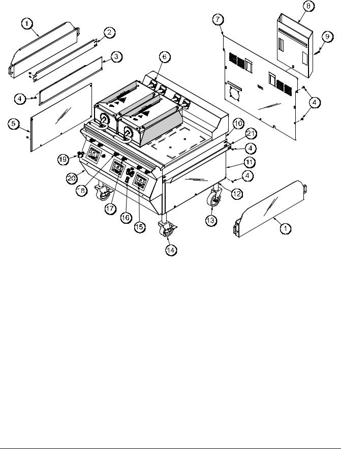
C811 Exploded View
Figure 1
ITEM |
DESCRIPTION |
PART NO. |
|
|
|
1 |
CAN A.-GREASE |
X80925 |
|
|
|
2 |
SLIDE-GREASE CAN LEFT |
069936 |
|
|
|
3 |
PANEL-SIDE-UPPER *LEFT |
073990 |
|
|
|
4 |
SCREW-10-32X3/8 SLTD TRUS |
024298 |
|
|
|
5 |
PANEL-SIDE-LOWER *LEFT |
073992 |
|
|
|
*6 |
KIT A.-GREASE SHIELD |
X78330-SER |
|
|
|
7 |
PANEL A.-BACK SERVICE |
X73993 |
|
|
|
8 |
DEFLECTOR A.-FLUE |
X69555 |
|
|
|
9 |
SCREW-3/8-16X34 SERR HWH |
017328 |
|
|
|
10 |
PANEL-SIDE-UPPER *RIGHT |
073989 |
|
|
|
11 |
PANEL-SIDE-LOWER *RIGHT |
073991 |
|
|
|
ITEM |
DESCRIPTION |
PART NO. |
|
|
|
12 |
NUT-JAM 1-1/2-12 (2 PCS) |
073594 |
|
|
|
13 |
CASTER-5" 7-5/8 STEM |
078377 |
|
|
|
14 |
CASTER-GRILL 5” SWIVEL LOC |
073240 |
|
|
|
15 |
KIT A.-GRILL CONTROL GEN |
X73474-SER |
|
|
|
16 |
SWITCH-ROCKER-DPST-10A |
076989-WP |
|
|
|
17 |
BUTTON-OPERATOR-BLACK |
076012 |
|
|
|
18 |
BUTTON-OPERATOR-RED |
076011 |
|
|
|
19 |
COVER A.-USB WATERPROOF |
068583 |
|
|
|
20 |
PANEL A.-FRONT UPPER |
X69550 |
|
|
|
21 |
PANEL A.-FRONT-LOWER |
X73979 |
|
|
|
22 |
SLIDE-GREASE CAN RIGHT |
069935 |
|
|
|
*NOTE: 1 KIT PER PLATEN
121003
Model 811, 813, 819, 821 Series |
7 |
Operator Parts Identification |
|
|
|

L811 Exploded View
Figure 2
ITEM |
DESCRIPTION |
PART NO. |
|
|
|
1 |
CAN A.-GREASE |
X80925 |
2 |
SLIDE-GREASE CAN LEFT |
069936 |
|
|
|
3 |
PANEL-SIDE-UPPER *LEFT |
073990 |
|
|
|
4 |
SCREW-10-32X3/8 SLTD TRUS |
024298 |
|
|
|
5 |
PANEL-SIDE-LOWER *LEFT |
073992 |
|
|
|
*6 |
KIT A.-GREASE SHIELD |
X78330-SER |
|
|
|
7 |
PANEL A.-BACK SERVICE |
X73993 |
|
|
|
8 |
DEFLECTOR A.-FLUE |
X69555 |
|
|
|
9 |
SCREW-3/8-16X34 SERR HWH |
017328 |
|
|
|
10 |
PANEL-SIDE-UPPER *RIGHT |
073989 |
|
|
|
11 |
PANEL-SIDE-LOWER *RIGHT |
073991 |
|
|
|
ITEM |
DESCRIPTION |
PART NO. |
|
|
|
12 |
NUT-JAM 1-1/2-12 (2 PCS) |
073594 |
13 |
CASTER-5" 7-5/8 STEM |
078377 |
|
|
|
14 |
CASTER-GRILL 5” SWIVEL LOC |
073240 |
|
|
|
15 |
KIT A.-GRILL CONTROL GEN |
X73474-SER |
|
|
|
16 |
SWITCH-ROCKER-DPST-10A |
076989-WP |
|
|
|
17 |
BUTTON-OPERATOR-BLACK |
076012 |
|
|
|
18 |
BUTTON-OPERATOR-RED |
076011 |
|
|
|
19 |
COVER A.-USB WATERPROOF |
068583 |
|
|
|
20 |
PANEL A.-FRONT-LOWER |
X73979 |
|
|
|
21 |
SLIDE-GREASE CAN RIGHT |
069935 |
|
|
|
*NOTE: 1 KIT PER PLATEN
120907
Operator Parts Identification |
8 |
Model 811, 813, 819, 821 Series |
|
|
|

C813 Exploded View
Figure 3
ITEM |
DESCRIPTION |
PART NO. |
|
|
|
1 |
CAN A.-GREASE |
X80925 |
|
|
|
2 |
SLIDE-GREASE CAN LEFT |
069936 |
|
|
|
3 |
PANEL-SIDE-UPPER *LEFT |
073990 |
|
|
|
4 |
SCREW-10-32X3/8 SLTD TRUS |
024298 |
|
|
|
5 |
PANEL-SIDE-LOWER-LEFT |
073992 |
|
|
|
*6 |
KIT A.-GREASE SHIELD |
X78330-SER |
|
|
|
7 |
PANEL A.-BACK SERVICE |
X73993 |
|
|
|
8 |
DEFLECTOR A.-FLUE |
X69555 |
|
|
|
9 |
SCREW-3/8-16X3/4 SERRATED |
017328 |
|
|
|
10 |
PANEL-SIDE-UPPER *RIGHT |
073989 |
|
|
|
11 |
PANEL-SIDE-LOWER-RIGHT |
073991 |
|
|
|
12 |
NUT-JAM 1 1/2-12 STEEL |
073594 |
|
|
|
ITEM |
DESCRIPTION |
PART NO. |
|
|
|
13 |
CASTER-5" 7-5/8 STEM |
078377 |
|
|
|
14 |
CASTER-GRILL 5" SWIVEL |
073240 |
|
W/LOCK |
|
15 |
KIT A.-GRILL CONTROL GEN |
X73474-SER |
|
|
|
16 |
SWITCH-ROCKER-DPST-10A |
076989-WP |
|
|
|
17 |
BUTTON-OPERATOR-BLACK |
076012 |
|
|
|
18 |
BUTTON-OPERATOR-RED |
076011 |
|
|
|
19 |
COVER A.-USB WATERPROOF |
068583 |
|
|
|
20 |
PANEL A.-FRONT UPPER |
X69550 |
|
|
|
21 |
PANEL A.-FRONT-LOWER |
X73979 |
|
|
|
22 |
SLIDE-GREASE CAN RIGHT |
069935 |
|
|
|
*NOTE: 1 KIT PER PLATEN
121003
Model 811, 813, 819, 821 Series |
9 |
Operator Parts Identification |
|
|
|
L813 Exploded View
Figure 4
ITEM |
DESCRIPTION |
PART NO. |
|
|
|
1 |
CAN A.-GREASE |
X80925 |
|
|
|
2 |
SLIDE-GREASE CAN LEFT |
069936 |
|
|
|
3 |
PANEL-SIDE-UPPER *LEFT |
073990 |
|
|
|
4 |
SCREW-10-32X3/8 SLTD TRUS |
024298 |
|
|
|
5 |
PANEL-SIDE-LOWER-LEFT |
073992 |
|
|
|
*6 |
KIT A.-GREASE SHIELD |
X78330-SER |
|
|
|
7 |
PANEL A.-BACK SERVICE |
X73993 |
|
|
|
8 |
DEFLECTOR A.-FLUE |
X69555 |
|
|
|
9 |
SCREW-3/8-16X3/4 SERRATED |
017328 |
|
|
|
10 |
PANEL-SIDE-UPPER *RIGHT |
073989 |
|
|
|
11 |
PANEL-SIDE-LOWER-RIGHT |
073991 |
|
|
|
ITEM |
DESCRIPTION |
PART NO. |
|
|
|
12 |
NUT-JAM 1 1/2-12 STEEL |
073594 |
|
|
|
13 |
CASTER-5" 7-5/8 STEM |
078377 |
|
|
|
14 |
CASTER-GRILL 5" SWIVEL |
073240 |
|
W/LOCK |
|
15 |
KIT A.-GRILL CONTROL GEN |
X73474-SER |
|
|
|
16 |
SWITCH-ROCKER-DPST-10A |
076989-WP |
|
|
|
17 |
BUTTON-OPERATOR-BLACK |
076012 |
|
|
|
18 |
BUTTON-OPERATOR-RED |
076011 |
|
|
|
19 |
COVER A.-USB WATERPROOF |
068583 |
|
|
|
20 |
PANEL A.-FRONT-LOWER |
X73979 |
|
|
|
21 |
SLIDE-GREASE CAN RIGHT |
069935 |
|
|
|
*NOTE: 1 KIT PER PLATEN
120907
Operator Parts Identification |
10 |
Model 811, 813, 819, 821 Series |
|
|
|
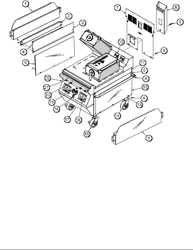
C819 Exploded View
Figure 5
ITEM |
DESCRIPTION |
PART NO. |
|
|
|
1 |
CAN A.-GREASE |
X80925 |
|
|
|
2 |
SLIDE-GREASE CAN LEFT |
069936 |
|
|
|
3 |
PANEL-SIDE UPPER-LEFT |
073990 |
|
|
|
4 |
SCREW-10-32X3/8 SLTD TRUS |
024298 |
|
|
|
5 |
PANEL-SIDE-LOWER-LEFT |
073992 |
|
|
|
6 |
SLIDE-GREASE CAN RIGHT |
069935 |
|
|
|
7 |
PANEL A.-BACK SERVICE |
X69664 |
|
|
|
8 |
DEFLECTOR A.-FLUE |
X69657 |
|
|
|
9 |
SCREW-3/8-16X1-1/2 SERR |
020129 |
|
|
|
*10 |
KIT A.-GREASE SHIELD |
X78330-SER |
|
|
|
11 |
PANEL-SIDE UPPER-RIGHT |
073989 |
|
|
|
12 |
PANEL-SIDE-LOWER-RIGHT |
073991 |
|
|
|
ITEM |
DESCRIPTION |
PART NO. |
|
|
|
13 |
NUT-JAM 1 1/2-12 STEEL |
073594 |
|
|
|
14 |
CASTER-5" 7-5/8 STEM |
078377 |
|
|
|
15 |
CASTER-GRILL 5" SWIVEL |
073240 |
|
W/LOCK |
|
16 |
KIT A.-GRILL CONTROL |
X73474-SER |
|
|
|
17 |
PANEL A.-FRONT-LOWER |
X69660 |
|
|
|
18 |
SWITCH-ROCKER-DPST-10A |
076989-WP |
|
|
|
19 |
COVER A.-USB WATERPROOF |
068583 |
|
|
|
20 |
BUTTON-OPERATOR-BLACK |
076012 |
|
|
|
21 |
BUTTON-OPERATOR-RED |
076011 |
|
|
|
22 |
PANEL A.-LIGHT |
X80626 |
|
|
|
*NOTE: 1 KIT PER PLATEN
121106
Model 811, 813, 819, 821 Series |
11 |
Operator Parts Identification |
|
|
|

L819 Exploded View
Figure 6
ITEM |
DESCRIPTION |
PART NO. |
|
|
|
1 |
CAN A.-GREASE |
X80925 |
|
|
|
2 |
SLIDE-GREASE CAN LEFT |
069936 |
|
|
|
3 |
PANEL-SIDE UPPER-LEFT |
073990 |
|
|
|
4 |
SCREW-10-32X3/8 SLTD TRUS |
024298 |
|
|
|
5 |
PANEL-SIDE-LOWER-LEFT |
073992 |
|
|
|
6 |
SLIDE-GREASE CAN RIGHT |
069935 |
|
|
|
7 |
PANEL A.-BACK SERVICE |
X69664 |
|
|
|
8 |
DEFLECTOR A.-FLUE |
X69657 |
|
|
|
9 |
SCREW-3/8-16X1-1/2 SERR |
020129 |
|
|
|
*10 |
KIT A.-GREASE SHIELD |
X78330-SER |
|
|
|
11 |
PANEL-SIDE UPPER-RIGHT |
073989 |
|
|
|
12 |
PANEL-SIDE-LOWER-RIGHT |
073991 |
|
|
|
ITEM |
DESCRIPTION |
PART NO. |
|
|
|
13 |
NUT-JAM 1 1/2-12 STEEL |
073594 |
|
|
|
14 |
CASTER-5" 7-5/8 STEM |
078377 |
|
|
|
15 |
CASTER-GRILL 5" SWIVEL |
073240 |
|
W/LOCK |
|
16 |
KIT A.-GRILL CONTROL |
X73474-SER |
|
|
|
17 |
PANEL A.-FRONT-LOWER |
X69660 |
|
|
|
18 |
SWITCH-ROCKER-DPST-10A |
076989-WP |
|
|
|
19 |
COVER A.-USB WATERPROOF |
068583 |
|
|
|
20 |
BUTTON-OPERATOR-BLACK |
076012 |
|
|
|
21 |
BUTTON-OPERATOR-RED |
076011 |
|
|
|
22 |
PANEL A.-LIGHT |
X80626 |
|
|
|
*NOTE: 1 KIT PER PLATEN
130316
Operator Parts Identification |
12 |
Model 811, 813, 819, 821 Series |
|
|
|

C821 Exploded View
Figure 7
ITEM |
DESCRIPTION |
PART NO. |
|
|
|
1 |
CAN A.-GREASE |
X80925 |
|
|
|
2 |
SLIDE-GREASE CAN LEFT |
069936 |
|
|
|
3 |
PANEL-SIDE UPPER-LEFT |
073990 |
|
|
|
4 |
SCREW-10-32X3/8 SLTD TRUS |
024298 |
|
|
|
5 |
PANEL-SIDE-LOWER-LEFT |
073992 |
|
|
|
6 |
PANEL A.-LIGHT |
X80626 |
|
|
|
7 |
PANEL A.-BACK SERVICE |
X69664 |
|
|
|
8 |
DEFLECTOR A.-FLUE |
X69657 |
|
|
|
9 |
SCREW-3/8-16X1-1/2 SERR |
020129 |
|
|
|
*10 |
KIT A.-GREASE SHIELD |
X78330-SER |
|
|
|
11 |
PANEL-SIDE UPPER-RIGHT |
073989 |
|
|
|
12 |
SLIDE-GREASE CAN RIGHT |
069935 |
|
|
|
ITEM |
DESCRIPTION |
PART NO. |
|
|
|
13 |
PANEL-SIDE-LOWER-RIGHT |
073991 |
|
|
|
14 |
NUT-JAM 1 1/2-12 STEEL |
073594 |
|
|
|
15 |
CASTER-5" 7-5/8 STEM |
078377 |
|
|
|
16 |
CASTER-GRILL 5" SWIVEL |
073240 |
|
W/LOCK |
|
17 |
KIT A.-GRILL CONTROL |
X73474-SER |
|
|
|
18 |
PANEL A.-FRONT-LOWER |
X69660 |
|
|
|
19 |
SWITCH-ROCKER-DPST-10A |
076989-WP |
|
|
|
20 |
COVER A.-USB WATERPROOF |
068583 |
|
|
|
21 |
BUTTON-OPERATOR-BLACK |
076012 |
|
|
|
22 |
BUTTON-OPERATOR-RED |
076011 |
|
|
|
*NOTE: 1 KIT PER PLATEN
121106
Model 811, 813, 819, 821 Series |
13 |
Operator Parts Identification |
|
|
|

L821 Exploded View
Figure 8
ITEM |
DESCRIPTION |
PART NO. |
|
|
|
1 |
CAN A.-GREASE |
X80925 |
|
|
|
2 |
SLIDE-GREASE CAN LEFT |
069936 |
|
|
|
3 |
PANEL-SIDE UPPER-LEFT |
073990 |
|
|
|
4 |
SCREW-10-32X3/8 SLTD TRUS |
024298 |
|
|
|
5 |
PANEL-SIDE-LOWER-LEFT |
073992 |
|
|
|
6 |
PANEL A.-LIGHT |
X80626 |
|
|
|
7 |
PANEL A.-BACK SERVICE |
X69664 |
|
|
|
8 |
DEFLECTOR A.-FLUE |
X69657 |
|
|
|
9 |
SCREW-3/8-16X1-1/2 SERR |
020129 |
|
|
|
*10 |
KIT A.-GREASE SHIELD |
X78330-SER |
|
|
|
11 |
PANEL-SIDE UPPER-RIGHT |
073989 |
|
|
|
12 |
SLIDE-GREASE CAN RIGHT |
069935 |
|
|
|
ITEM |
DESCRIPTION |
PART NO. |
|
|
|
13 |
PANEL-SIDE-LOWER-RIGHT |
073991 |
|
|
|
14 |
NUT-JAM 1 1/2-12 STEEL |
073594 |
|
|
|
15 |
CASTER-5" 7-5/8 STEM |
078377 |
|
|
|
16 |
CASTER-GRILL 5" SWIVEL |
073240 |
|
W/LOCK |
|
17 |
KIT A.-GRILL CONTROL |
X73474-SER |
|
|
|
18 |
PANEL A.-FRONT-LOWER |
X69660 |
|
|
|
19 |
SWITCH-ROCKER-DPST-10A |
076989-WP |
|
|
|
20 |
COVER A.-USB WATERPROOF |
068583 |
|
|
|
21 |
BUTTON-OPERATOR-BLACK |
076012 |
|
|
|
22 |
BUTTON-OPERATOR-RED |
076011 |
|
|
|
*NOTE: 1 KIT PER PLATEN
130318
Operator Parts Identification |
14 |
Model 811, 813, 819, 821 Series |
|
|
|
 Loading...