


C723

OPERATOR'S
MANUAL
Model C723
Soft Serve Freezer
Original Operating Instructions
069127-M
3/18/11 (Original Publication)
(Updated 7/18/14)

Complete this page for quick reference when service is required:
Taylor Distributor:
Address:
Phone:
Service:
Parts:
Date of Installation:
Information found on the data label:
Model Number:
Serial Number:
Electrical Specs: Voltage Cycle
Phase
Maximum Fuse Size: A
Minimum Wire Ampacity: A
E 2011 Carrier Commercial Refrigeration, Inc.
069127-M
Any unauthorized reproduction, disclosure, or distribution of copies by any person of any portion of this
work may be a violation of Copyright Law of the United States of America and other countries, could result
in the awarding of Statutory Damages of up to $250,000 (17 USC 504) for infringement, and may result
in further civil and criminal penalties. All rights reserved.
Taylor Company
a division of Carrier Commercial Refrigeration, Inc.
750 N. Blackhawk Blvd.
Rockton, IL 61072

Table of Contents
Section 1 To th e Installer 1............................................
Installer Safety 1........................................................
Site Preparation 1.......................................................
Air Cooled Units 1.......................................................
Water Connections (Water Cooled Units Only) 2............................
Electrical Connections 2.................................................
Beater Rotation 3.......................................................
Optional Carts 3........................................................
Refrigerant 3...........................................................
Section 2 To the Operator 4...........................................
Section 3 Safety 5....................................................
Section 4 Operator Parts Id entification 8...............................
Model C723 8..........................................................
Model C723 - Factory Equipped With Agitator 10.............................
Model C723 - Door and Beater Assembly 12................................
Optional Carts 13........................................................
Accessories 14..........................................................
Brushes 15..............................................................
Section 5 Important: To the Operator 16.................................
Symbol Definitions 17....................................................
Operating Screen Descriptions 20..........................................
Manager's Menu 21......................................................
Section 6 Operating Procedures 27.....................................
Assembly 27............................................................
Sanitizing 32............................................................
Priming 34..............................................................
Manual Brush Cleaning 34................................................
Draining Product From T he Freezing Cylinder 34............................
Rinsing 35..............................................................
Table of Contents Model C723

Table of Contents - Page 2
Hopper Cleaning 35......................................................
Disassembly 36..........................................................
Brush Cleaning 36.......................................................
Section 7 Important: Operator Checklist 37..............................
During Cleaning and Sanitizing 37.........................................
Troubleshooting Bacterial Count 37........................................
Regular Maintenance Checks 37...........................................
Winter Storage 38........................................................
Section 8 Troubleshooting Guide 39....................................
Section 9 Parts Replacement Schedule 42...............................
Section 10 Limited Warranty on Equipment 43............................
Section 11 Limited Warranty on Parts 45.................................
Section 12 Parts List 48.................................................
Wiring Diagrams 62......................................................
Note: Continuing research results in stead y improvements; therefore, information
in this manual is subject to change without notice.
Note: Only instructions originating from the factory or its authorized translation
representative(s) are considered to be the original set of in structions.
E 2011 Carrier Commercial Refrigeration, Inc. (Original Publication)
Updated July, 2014
069127-M
Any unauthorized reproduction, disclosure, or distribution of copies by any person of any portion of this
work may be a violation of Copyright Law of the United States of America and other countries, could result
in the awarding of Statutory Damages of up to $250,000 (17 USC 504) for infringement, and may result
in further civil and criminal penalties.
All rights reserved.
Taylor Company
a division of Carrier Commercial Refrigeration, Inc.
750 N. Blackhawk Blvd.
Rockton, IL 61072
Model C723 Table of Contents
Section 1 To the Installer
The following information has been included in the
manual as safety and regulatory guidelines. For
complete installation instructions, please see the
Installation Checklist.
Installer Safety
In all areas of the world, equipment should
be installed in accordance with existing local codes.
Please contact your local authorities if you have any
questions.
Care should be taken to ensure that all basic safety
practices are followed during the installation and
servicing activities related to the installation and
service of Taylor equipment.
S Only authorized Taylor service personnel
should perform installation and repairs on
the equipment.
S Authorized service personnel should consult
OSHA Standard 29CFRI910.147 or the
applicable code of the local area for the
industry standards on lockout/tagout
procedures before beginning any installation
or repairs.
S Authorized service personnel must ensure
that the proper PPE is available and worn
when required during installation and
service.
S Authorized service personnel must remove
all metal jewelry, rings, and watches before
working on electrical equipment.
cause severe injuries.
Site Preparation
Review the area where the unit will be installed
before uncrating the unit. Make sure all possible
hazards to the user or equipment have been
addressed.
Air Cooled Units
The Model C723 air cooled unit requires a minimum
of 6” (152 mm) on the left and right sides and 0” on
the back. The Model C723 unit equipped with top air
discharge requires 6” (152 mm) on the left side, 0”
on the right side, and 0” on the back.
This will allow for adequate air flow across the
condenser. Failure to allow adequate clearance can
reduce the refrigeration capacity of the freezer and
possibly cause permanent damage to the
compressor.
For Indoor Use Only: This unit is designed to
operate indoors, under normal ambient
temperatures of 70_-75_F(21_-24_C). The freezer
has successfully performed in high ambient
temperatures of 104_(40_C) at reduced capacities.
where a water jet or hose can be used. NEVER use
a water jet or hose to rinse or clean the unit. Failure
to follow this instruction may result in electrocution.
This unit has many sharp edges that can
This unit must NOT beinstalledinanarea
The main power supply(s) to the freezer
must be disconnected prior to performing any
repairs. Failure to follow this instruction may result in
personal injury or death from electrical shock or
hazardous moving parts as well as poor
performance or damage to the equipment.
Note:Allrepairsmustbeperformedbyan
authorized Taylor Service Technician.
Model C723 To the Installer
to avoid the hazard of tipping. Extreme care should
be taken in moving this equipment for any reason.
Two or more people are required to safely move this
unit. Failure to comply may result in personal injury
or equipment damage.
Uncrate the unit and inspect it for damage. Report
any damage to your Taylor Distributor.
1
This unit must be installed on a level surface
131121

This piece of equipment is made in the USA and has
USA sizes of hardware. All metric conversions are
approximate and vary in size.
Water Connections
(Water Cooled Units Only)
An adequate cold water supply must be provided
with a hand shut-off valve. On the back, right side of
the unit, two 3/8” I.P.S. water connections for inlet
and outlet are provided for easy hook-up. 1/2” inside
diameter water lines should be connected to the
machine. (Flexible lines are recommended, if local
codes permit.) Depending on local water conditions,
it may be advisable to install a water strainer to
prevent foreign substances from clogging the
automatic water valve. There will be only one water
“in” and one water “out” connection. DO NOT install
a hand shut-off valve on the water “out” line! Water
should always flow in this order: first, through the
automatic water valve; second, through the
condenser; and third, through the outlet fitting to an
opentrapdrain.
A back flow prevention device is
required on the incoming water connection side.
Please refer to the applicable National, State, and
local codes for determining the proper configuration.
Electrical Connections
In the United States, this equipment is intended to
be installed in accordance with the National
Electrical Code (NEC), ANSI/NFPA 70-1987. The
purpose of the NEC code is the practical
safeguarding of persons and property from hazards
arising from the use of electricity. This code contains
provisions considered necessary for safety. In all
other areas of the world, equipment should be
installed in accordance with the existing local codes.
Please contact your local authorities.
FOLLOW YOUR LOCAL ELECTRICAL CODES!
specifications. Refer to the wiring diagram provided
inside of the electrical box for proper power
connections.
CAUTION: THIS EQUIPMENT MUST BE
PROPERLY GROUNDED! FAILURE TO DO SO
CAN RESULT IN SEVERE PERSONAL INJURY
FROM ELECTRICAL SHOCK!
This unit is provided with an equipotential
grounding lug that is to be properly attached to the
rear of the frame by the authorized installer. The
installation location is marked by the equipotential
bonding symbol (5021 of IEC 60417-1) on both the
removable panel and the equipment's frame.
S Appliances that are permanently connected
to fixed wiring and for which leakage
currents may exceed 10 mA, particularly
when disconnected or not used for long
periods, or during initial installation, shall
have protective devices such as a GFI, to
protect against the leakage of current,
installed by the authorized personnel to the
local codes.
S Stationary appliances which are not
equipped with a power cord and a plug or
another device to disconnect the appliance
from the power source must have an all-pole
disconnecting device with a contact gap of
at least 3 mm installed in the external
installation.
S Supply cords used with this unit shall be
oil-resistant, sheathed flexible cable not
lighter than ordinary polychloroprene or
other equivalent synthetic
elastomer-sheathed cord (Code designation
60245 IEC 57) installed with the proper cord
anchorage to relieve conductors from strain,
including twisting, at the terminals and
protect the insulation of the conductors from
abrasion.
Each unit requires one power supply for each data
label on the unit. Check the data label(s) on the
freezer for branch circuit overcurrent protection or
fuse, circuit ampacity, and other electrical
130225
If the supply cord is damaged, it must be
replaced by the manufacturer, its service
agent, or similarly qualified person, in order
to avoid a hazard.
2
Model C723To the Installer
Beater Rotation
Refrigerant
Beater rotation must be clockwise as viewed
looking into the freezing cylinder.
Note: The following procedures should be performed
by a trained service technician.
To correct the rotation on a three-phase unit,
interchange any two incoming power supply lines at
freezer main terminal block only.
To correct rotation on a single-phase unit, change
the leads inside the beater motor. (Follow the
diagram printed on the motor.)
Electrical connections are made directly to the
terminal block provided in the splice box.
Optional Carts
There are two optional carts available.
1. C20600-AFB: ADA compliant height cart,
not equipped with a door.
In consideration of our environment, Taylor
uses only earth friendly HFC refrigerants. The HFC
refrigerant used in this unit is R404A. This
refrigerant is generally considered non-toxic and
non-flammable, with an Ozone Depleting Potential
(ODP) of zero (0).
However, any gas under pressure is potentially
hazardous and must be handled with caution.
NEVER fill any refrigerant cylinder completely with
liquid. Filling the cylinder to approximately 80% will
allow for normal expansion.
Use only R404A refrigerant that conforms
to the AHRI standard 700 specification. The use of
any other refrigerant may expose users and
operators to unexpected safety hazards.
Refrigerant liquid sprayed onto the skin may
cause serious damage to tissue. Keep eyes and skin
protected. If refrigerant burns should occur, flush
immediately with cold water. If burns are severe,
apply ice packs and contact a physician
immediately.
2. C20600-000: Standard height cart with
reversible front door panel and rear panel.
Note: If the door is required on the rear of the
cart instead of the front, the front door panel
and the rear panel can be reversed. To reverse
these panels, remove the five screws on each
panel. Reverse and reinstall the panels, making
sure all screws are reinstalled.
IMPORTANT! For safety purposes, the
freezer must be bolted to the cart using all 4
bolts. Failure to comply could result in personnel
injury and equipment damage.
Model C723 To the Installer
government laws regarding refrigerant recovery,
recycling, and reclaiming systems. If you have any
questions regarding these laws, please contact the
factory Service Department.
conjunction with polyolester oils is extremely
moisture absorbent. When opening a refrigeration
system, the maximum time the system is open must
not exceed 15 minutes. Cap all open tubing to
prevent humid air or water from being absorbed by
the oil.
3
Taylor reminds technicians to be cautious of
WARNING: R404A refrigerant used in
130923

Section 2 To the Operator
Your freezer has been carefully engineered and
manufactured to give you dependable operation.
This unit, when properly operated and cared for, will
produce a consistent quality product. Like all
mechanical products, it will require cleaning and
maintenance. A minimum amount of care and
attention is necessary if the operating procedures
outlined in this manual are followed closely.
This Operator's Manual should be read
before operating or performing any maintenance on
your equipment.
Your Taylor freezer will NOT eventually compensate
for and correct any errors during the set-up or filling
operations. Thus, the initial assembly and priming
procedures are of extreme importance. It is strongly
recommended that personnel responsible for the
equipment's operation, both assembly and
disassembly, go through these procedures together
in order to be properly trained and to make sure that
no confusion exists.
In the event you should require technical assistance,
please contact your local authorized Taylor
Distributor.
Your Taylor warranty is valid only if the parts are
authorized Taylor parts, purchased from the local
authorized Taylor Distributor, and only if all required
service work is provided by an authorized Taylor
service technician. Taylor reserves the right to deny
warranty claims on units or parts if non-Taylor
approved parts or incorrect refrigerant were installed
in the unit, system modifications were performed
beyond factory recommendations, or it is determined
that the failure was caused by abuse, misuse,
neglect, or failure to follow all operating instructions.
For full details of your Taylor Warranty, please see
the Limited Warranty section in this manual.
Note: Constant research results in steady
improvements; therefore, information in this
manual is subject to change without notice.
If the crossed out wheeled bin symbol is
affixed to this product, it signifies that this product is
compliant with the EU Directive as well as other
similar legislation in effect after August 13, 2005.
Therefore, it must be collected separately after its
use is completed, and cannot be disposed as
unsorted municipal waste. The user is responsible
for returning the product to the appropriate collection
facility, as specified by the local code.
For additional information regarding applicable local
laws, please contact the municipal facility and/or
local distributor.
Compressor Warranty Disclaimer
The refrigeration compressor(s) on this unit are
warranted for the term stated in the Limited
Warranty section in this manual. However, due to
the Montreal Protocol and the U.S. Clean Air Act
Amendments of 1990, many new refrigerants are
being tested and developed, thus seeking their way
into the service industry. Some of these new
refrigerants are being advertised as drop-in
replacements for numerous applications. It should
be noted that in the event of ordinary service to this
unit's refrigeration system, only the refrigerant
specified on the affixed data label should be
used. The unauthorized use of alternate refrigerants
will void your Taylor compressor warranty. It is the
unit owner's responsibility to make this fact known to
any technician he employs.
It should also be noted that Taylor does not warrant
the refrigerant used in its equipment. For example, if
the refrigerant is lost during the course of ordinary
service to this machine, Taylor has no obligation to
either supply or provide its replacement either at
billable or unbillable terms. Taylor does have the
obligation to recommend a suitable replacement if
the original refrigerant is banned, obsoleted, or no
longer available during the five year warranty of the
compressor.
Taylor will continue to monitor the industry and test
new alternates as they are being developed. Should
a new alternate prove, through our testing, that it
would be accepted as a drop-in replacement, then
the above disclaimer would become null and void.
To find out the current status of an alternate
refrigerant as it relates to your compressor warranty,
call the local Taylor Distributor or the Taylor Factory.
Be prepared to provide the Model/Serial Number of
the unit in question.
131121
4
Model C723To the Operator
Section 3 Safety
We, at Taylor Company, are concerned about the
safety of the operator when he or she comes in
contact with the freezer and its parts. Taylor has
gone to extreme efforts to design and manufacture
built-in safety features to protect both you and the
service technician. As an example, warning labels
have been attached to the freezer to further point
out safety precautions to the operator.
IMPORTANT - Failure to adhere to the
following safety precautions may result in
severe personal injury or death. Failure to
comply with these warnings may damage the
machine and its components. Component
damage will result in part replacement expense
and service repair expense.
DO NOT operate the freezer without
reading this Operator Manual. Failure to follow this
instruction may result in equipment damage, poor
freezer performance, health hazards, or personal
injury.
This appliance is to be used only by trained
personnel. It is not intended for use by children or
people with reduced physical, sensory, or mental
capabilities, or lack of experience and knowledge,
unless given supervision or instruction concerning
the use of the appliance by a person responsible for
their safety.
This unit is provided with an equipotential
grounding lug that is to be properly attached to the
rear of the frame by the authorized installer. The
installation location is marked by the equipotential
bonding symbol (5021 of IEC 60417-1) on both the
removable panel and the equipment's frame.
S All repairs must be performed by an
authorized Taylor service technician.
S The main power supplies to the machine
must be disconnected prior to performing
any repairs.
S DO NOT operate the freezer unless it is
properly grounded.
S DO NOT operate the freezer with larger
fuses than specified on the freezer data
label.
S Appliances that are permanently connected
to fixed wiring and for which leakage
currents may exceed 10 mA, particularly
when disconnected or not used for long
periods, or during initial installation, shall
have protective devices such as a GFI, to
protect against the leakage of current,
installed by the authorized personnel to the
local codes.
S Stationary appliances which are not
equipped with a power cord and a plug or
another device to disconnect the appliance
from the power source must have an all-pole
disconnecting device with a contact gap of
at least 3 mm installed in the external
installation.
S Supply cords used with this unit shall be
oil-resistant, sheathed flexible cable not
lighter than ordinary polychloroprene or
other equivalent synthetic
elastomer-sheathed cord (Code designation
60245 IEC 57) installed with the proper cord
anchorage to relieve conductors from strain,
including twisting, at the terminals and
protect the insulation of the conductors from
abrasion.
If the supply cord is damaged, it must be
replaced by the manufacturer, its service
agent, or similarly qualified person, in order
to avoid a hazard.
DO NOT use a water jet to clean or rinse
the freezer. Failure to follow these instructions may
result in serious electrical shock.
Model C723 Safety
Failure to follow these instructions may result in
electrocution. Contact your local authorized Taylor
Distributor for service.
130225
5
S DO NOT allow untrained personnel to
operate this machine.
S DO NOT operate the freezer unless all
service panels and access doors are
restrained with screws.
S DO NOT remove any internal operating
parts (examples: freezer door, beater,
scraper blades, etc.) unless all control
switches are in the OFF position.
Failure to follow these instructions may result in
severe personal injury to fingers or hands from
hazardous moving parts.
This unit has many sharp edges that can
cause severe injuries.
S DO NOT put objects or fingers in the door
spout. This may contaminate the product
and cause severe personal injury from blade
contact.
S USE EXTREME CAUTION when removing
the beater asssembly. The scraper blades
are very sharp.
S CAUTION-SHARP EDGES: Two people are
required to handle the cup/cone dispenser.
Protective gloves must be worn and the
mounting holes must NOT be used to lift or
hold the dispenser. Failure to follow this
instruction can result in personal injury to
fingers or equipment damage.
Thismachinemustbeplacedonalevel
surface. Extreme care should be taken in moving it
for any reason. Two or more persons are required to
safely move this machine. Failure to comply may
result in personal injury or equipment damage.
Cleaning and sanitizing schedules are
governed by your state or local regulatory agencies
and must be followed accordingly. Please refer to
the cleaning section of this manual for the proper
procedure to clean this unit.
DO NOT obstruct air intake and discharge openings:
The Model C723 air cooled unit requires a minimum
of 6” (152 mm) on the left and right sides and 0” on
the back. The Model C723 unit equipped with top air
discharge requires 6” (152 mm) on the left side, 0”
on the right side, and 0” on the back.
This will allow for adequate air flow across the
condenser. Failure to allow adequate clearance can
reduce the refrigeration capacity of the freezer and
possibly cause permanent damage to the
compressor.
For Indoor Use Only: This unit is designed to
operate indoors, under normal ambient
temperatures of 70° - 75°F (21° - 24°C). The freezer
has successfully performed in high ambient
temperatures of 104°(40°C) at reduced capacities.
DO NOT run the machine without product. Failure to
follow this instruction can result in damage to the
machine.
Access to the service area of the unit is
restricted to persons having knowledge and practical
experience with the appliance, in particular as far as
safety and hygiene are concerned.
130225
NOISE LEVEL: Airborne noise emission does not
exceed 78 dB(A) when measured at a distance of
1.0 meter from the surface of the machine and at a
height of 1.6 meters from the floor.
6
Model C723Safety

Notes:
Model C723 Safety
7
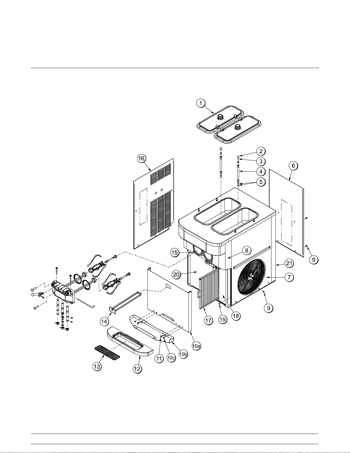
Section 4 Operator Parts Identification
Model C723
140519
Figure 1
8
Model C723Operator Parts Identification
Model C723 Exploded View Parts Identification
ITEM DESCRIPTION PART NO.
1 COVER-HOPPER 041682-BLA
2 ORIFICE 022465-100
3 O-RING-3/8 OD X .070W
(100 TO BAG)
4 TUBE A.-FEED-SS-5/32 HOLE X29429-2
5 O-RING-.643 OD X .077W
(50 TO BAG)
6 PANEL-REAR 069340
7 PANEL A.-SIDE RIGHT X68854
8 PANEL A.-FRONT X81843
9 SCREW-1/4-20X3/8 SLTD 011694
10 PANEL A.-SHELF (INCLUDES
ITEMS 10a -10c)
10a PANEL A.-FRONT-LOWER X81841
10b SHELF-DRIP TRAY 080782
016137
018572
X81840
ITEM DESCRIPTION PART NO.
10c SCREW-1/4-20X3/8 SLTD 011694
11 SCREW-WINGHEAD 081582
12 TRAY-DRIP 080781
13 SHIELD-SPLASH-WIRE 046177-SP
14 PAN A.-DRIP 15 1/8 LONG X51601
15 STUD-NOSE CONE 055987
16 PANEL-SIDE LEFT 068851
17 FILTER ASSEMBLY X81440
17a FILTER-AIR-18.28X15.5X.70 052779-15
18 COVER-ACCESS-FRONT-R. 068844
19 SCREW-10X3/8 SLOTTED HEX 015582
20 COVER-ACCESS-LEFT 081834
TRIM-REAR CORNER-R 068847
21
TRIM-REAR CORNER-L 080238
140519
Model C723 Operator Parts Identification
9

Model C723 - Factory Equipped With Agitator
140519
Figure 2
10
Model C723Operator Parts Identification

Model C723 Factory Equipped With Agitator Exploded View Parts Identification
ITEM DESCRIPTION PART NO.
1 COVER-HOPPER-14 QT-GRAY 041682-GRY
2 ORIFICE 022465-100
3 O-RING-3/8 OD X .070W
(100 TO BAG)
4 TUBE A.-FEED-SS-5/32 HOLE X29429-2
5 O-RING-.643 OD X .077W
(50 TO BAG)
6 PANEL-REAR 069340
7 PANEL A.-SIDE RIGHT X68854
8 PANEL A.-FRONT X81843
9 SCREW-1/4-20X3/8 SLTD 011694
10 PANEL A.-SHELF
(INCLUDES ITEMS 10a -10c)
10a PANEL A.-FRONT-LOWER X81841
10b SHELF-DRIP TRAY 080782
016137-SER
018572-SER
X81840
ITEM DESCRIPTION PART NO.
10c SCREW-1/4-20X3/8 SLTD 011694
11 SCREW-WINGHEAD 081582
12 TRAY-DRIP 080781
13 SHIELD-SPLASH-WIRE 046177-SP
14 PAN A.-DRIP 15 1/8 LONG X51601
15 STUD-NOSE CONE 055987
16 PANEL-SIDE LEFT 068851
17 FILTER A. X81440
18 COVER-ACCESS-FRONT-R. 081833
19 SCREW-10X3/8 SLOTTED HEX 015582
20 COVER-ACCESS-LEFT 081834
21 AGITATOR 056592-SP
TRIM-REAR CORNER-R 068847
22
TRIM-REAR CORNER-L 080238
140519
Model C723 Operator Parts Identification
11

Model C723 - Door and Beater Assembly
ITEM DESCRIPTION PART NO.
1 PLUG-PRIME TWIN 059936
2 O-RING-1/2OD X .070W
(50 TO BAG)
3 GASKET-DOOR HT 4"-DOUBLE 048926
4 BEARING-FRONT 050216
5 BEATER A.-2.8QT-HELICORE X35466
6 BLADE-SCRAPER-PLASTIC 035480
7 SHAFT-BEATER 054194
8 SEAL-DRIVE SHAFT 032560
9 PIN-HANDLE-TWIN 059894
10 VALVE A.-DRAW X69615
11 O-RING-13/16 OD X .103W
(25 TO BAG)
140519
024278
019330
Figure 3
12
ITEM DESCRIPTION PART NO.
12 CAP-DESIGN 1.010"ID-6 POINT 014218
13 SEAL-DRAW VALVE-LARGE
H-RING
14 VALVE A.-DRAW-CENTER X62218
15 NUT-STUD-BLACK 2.563 LONG 058764
16 SCREW-ADJUSTMENT-5/16-24 056332
17 O-RING-1/4 OD X .070W 50
(25 TO BAG)
18 HANDLE A.-DRAW X56421-1
19 NUT-STUD-BLACK 3.250 LONG 058765
20 DOOR A.-*SH BAF*W/PRG X68889-SER
20a BAFFLE A.-SHORT 4 IN X50883
034698
015872
Model C723Operator Parts Identification
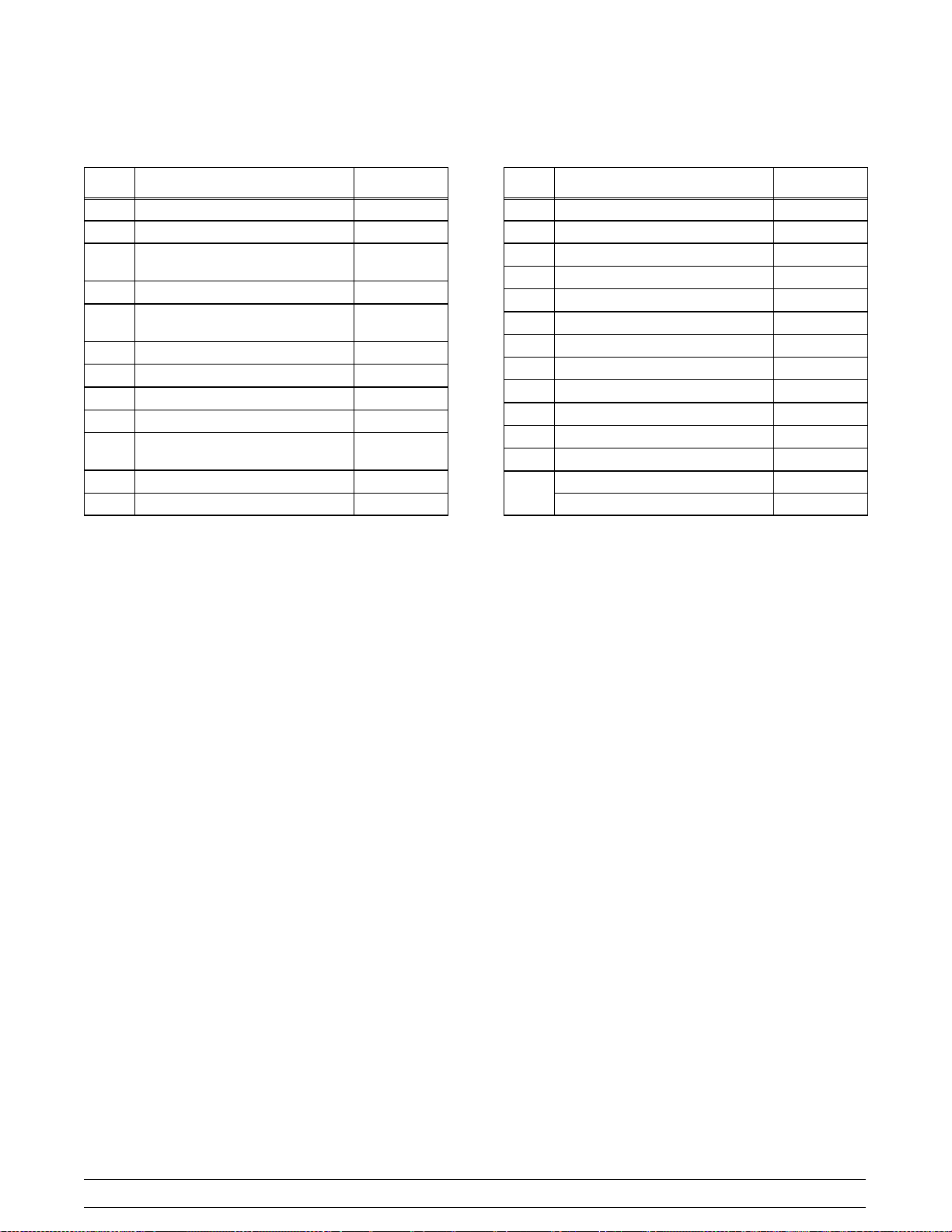
Optional Carts
Cart A.-ADA (X69400) CartA.-Std (X69425)
ITEM DESCRIPTION PART NO.
1 SCREW-10-32X1/2SLTD TRUSS 037734
2 PANEL-FRONT/REAR-ADA 069402
3 CASTER-3" SWV 3/4-10 STEM
W/BRAKE
4 PANEL-SIDE-CART 069403
5 CASTER-3" SWV 3/4-10 STEM 021279
NOTE: ADA COMPLIANT HEIGHT CART, NOT
EQUIPPED WITH A DOOR.
030307
Figure 4
ITEM
1 PANEL A.-STD CART-FRONT X69426
2 DOOR A.-STD CART X69295
3 SCREW-10-32X1/2SLTD TRUSS 037734
4 HANDLE-STNLS FLUSH PULL 019043
5 CASTER-3" SWV 3/4-10 STEM
W/BRAKE
6 PANEL-SIDE-STD CART 069428
7 PANEL-REAR-STD CART 069429
NOTE: STANDARD HEIGHT CART WITH
REVERSIBLE FRONT DOOR PANEL AND REAR
PANEL.
DESCRIPTION PART NO.
030307
140519
Model C723 Operator Parts Identification
13
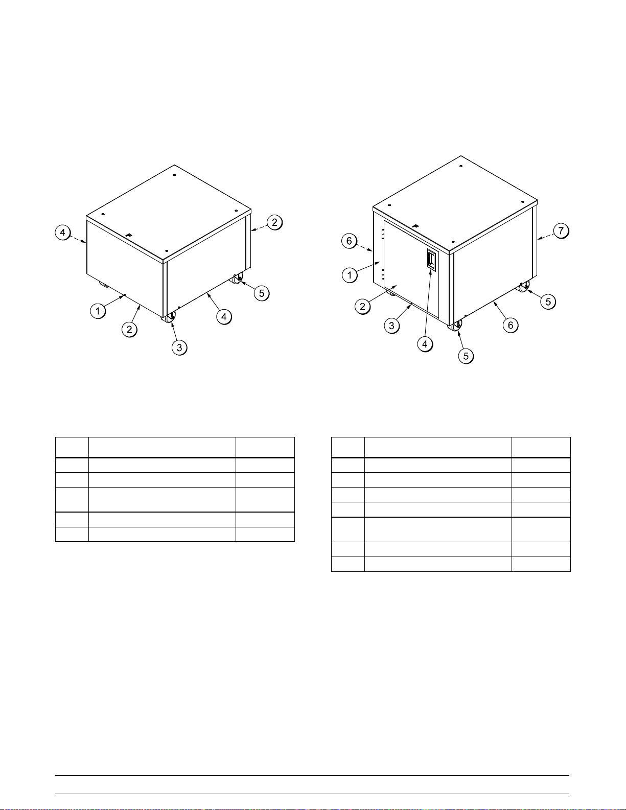
Accessories
ITEM DESCRIPTION PART NO.
1 LUBRICANT-TAYLOR 4 OZ. 047518
2 TOOL-O-RING REMOVAL 048260-WHT
*3 SANITIZER-STERA SHEEN SEE NOTE
140718
Figure 5
14
ITEM DESCRIPTION PART NO.
4 PAIL-10 QT 013163
** KIT A.-TUNE-UP X49463-80
*A sample container of sanitizer is sent with the unit. For
reorders,orderStera Sheen part no. 055492 (100 2 oz.
packs) or Kay-5 part no. 041082 (200 packs).
**NotShown.
Model C723Operator Parts Identification
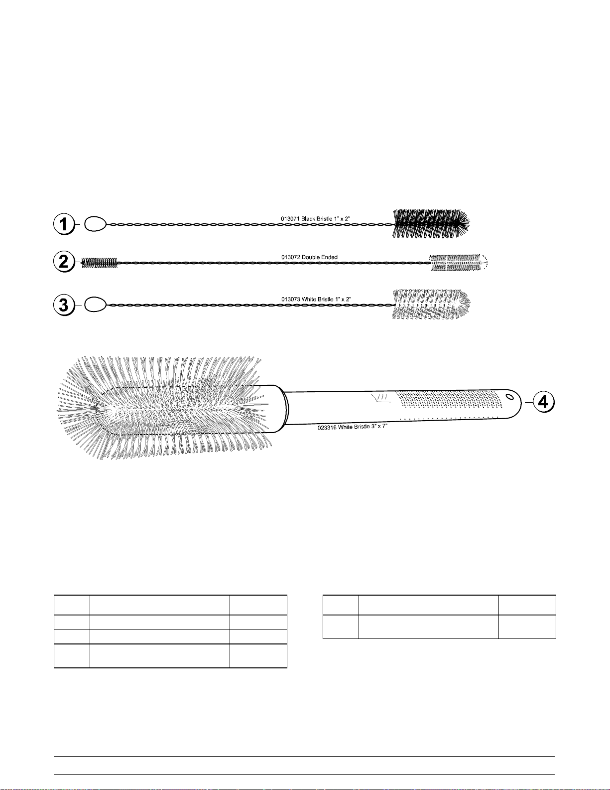
Brushes
Figure 6
ITEM DESCRIPTION PART NO.
1 BLACK BRISTLE BRUSH 013071
2 DOUBLE END BRUSH 013072
3 WHITE BRISTLE BRUSH
(1” x 2”)
013073
Model C723 Operator Parts Identification
ITEM DESCRIPTION PART NO.
4 WHITE BRISTLE BRUSH
(3” x 7”)
15
023316
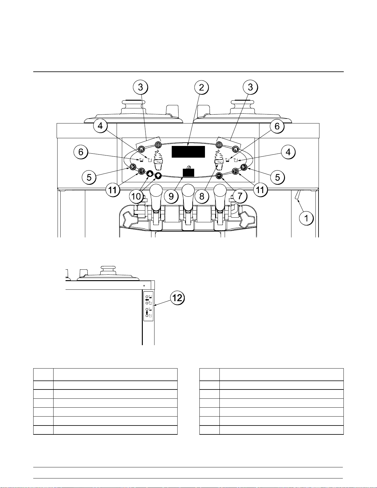
Section 5 Important: To the Operator
Model C723
ITEM DESCRIPTION
1 POWER SWITCH
2 LIQUID CRYSTAL DISPLAY
3 KEYPADS
4 MIX OUT INDICATOR
5 STANDBY KEY
6 MIX LOW INDICATOR
130425
Figure 7
16
ITEM DESCRIPTION
7 SELECT KEY
8 SERVICE MENU KEY
9 BRUSH CLEAN COUNTER
10 ARROW KEYS
11 SYRUP HEATER KEY (INACTIVE)
*12 DECAL-REAR MIX L IGHTS
*FACTORY INSTALLED OPTION
Model C723Important: To the Operator
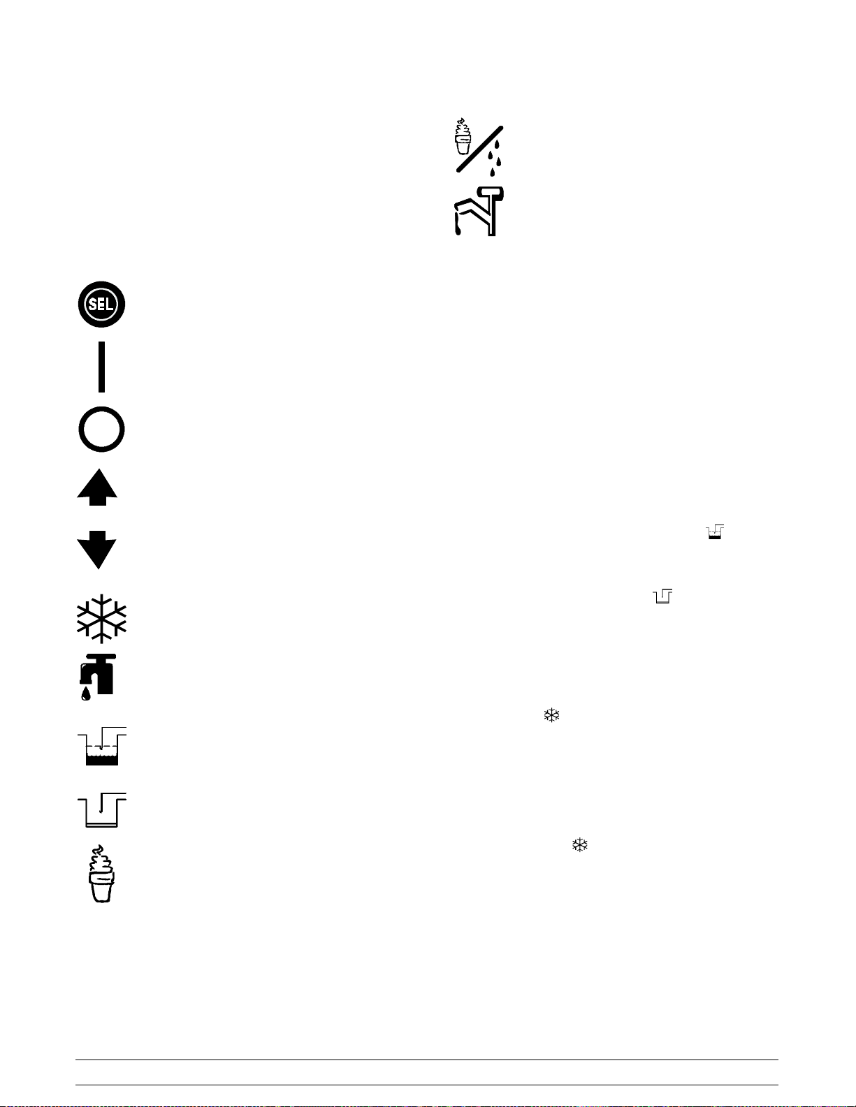
Symbol Definitions
To better communicate in the International arena,
symbols have replaced words on many of our
operator switches, function, and fault indicators.
Your Taylor equipment is designed with these
International symbols.
The following chart identifies the symbol definitions.
= SELECT
= STANDBY
= TOPPING HEATER
Power Switch
When placed in the ON position, the power switch
allows control panel operation.
=ON
=OFF
= UP ARROW
= DOWN ARROW
=AUTO
= WASH
=MIXLOW
Fluorescent Display
The fluorescent display is located on the front
control panel. During normal operation, the display is
blank. The display is used to show menu options
and notifies the operator if a fault is detected. On
International models, the display will indicate the
temperature of the mix in the hopper.
Indicator Lights
MIX LOW - When the MIX LOW symbol is
illuminated, the mix hopper has a low supply of mix
and should be refilled as soon as possible.
MIX OUT - When the MIX OUT
illuminated, the mix hopper has been almost
completely exhausted and has an insufficient supply
of mix to operate the freezer. At this time, the AUTO
mode is locked out and the freezer will be placed in
the STANDBY mode. To initiate the refrigeration
system, add mix to the mix hopper and touch the
AUTO symbol
begin operation.
Optional feature: Some freezers are equipped with
rear indicator lights.
. The freezer will automatically
symbol is
= MIX OUT
Auto Symbol
The AUTO symbol will illuminate when it is
= MENU DISPLAY
Model C723 Important: To the Operator
touched. This indicates that the refrigeration system
has been activated. In the AUTO mode, the WASH
or STANDBY functions are automatically cancelled.
130430
17
 Loading...