


Models H62 & H63
Shake/Slush Freezers
Original Operating Instructions
067343-M
4/1/09 (Original Publication)
(Updated 4/16/12)

Complete this page for quick reference when service is required:
Taylor Distributor:
Address:
Phone:
Service:
Parts:
Date of Installation:
Information found on the data label:
Model Number:
Serial Number:
Electrical Specs: Voltage |
|
Cycle |
|||||
Phase |
|
|
|
|
|
||
Maximum Fuse Size: |
|
|
|
|
A |
||
Minimum Wire Ampacity: |
|
|
|
|
A |
||
E April, 2009 Taylor All rights reserved. 067343--M
The word Taylor and the Crown design
are registered trademarks in the United States of America and certain other countries.
Taylor Company
750 N. Blackhawk Blvd.
Rockton, IL 61072

Table of Contents
Section 1 |
To the Installer . . . . . . . . . . . . . . . . . . . . . . . . . . . . . . . . . . . . . . . . . . . . |
1 |
Installer Safety . . . . . . . . . . . . . . . . . . . . . . . . . . . . . . . . . . . . . . . . . . . . . . . . . . . . . . . . |
1 |
|
Site Preparation . . . . . . . . . . . . . . . . . . . . . . . . . . . . . . . . . . . . . . . . . . . . . . . . . . . . . . . |
1 |
|
Air Cooled Units . . . . . . . . . . . . . . . . . . . . . . . . . . . . . . . . . . . . . . . . . . . . . . . . . . . . . . . |
2 |
|
Water Connections (Water Cooled Units Only) . . . . . . . . . . . . . . . . . . . . . . . . . . . . |
2 |
|
Electrical Connections . . . . . . . . . . . . . . . . . . . . . . . . . . . . . . . . . . . . . . . . . . . . . . . . . |
2 |
|
Beater Rotation . . . . . . . . . . . . . . . . . . . . . . . . . . . . . . . . . . . . . . . . . . . . . . . . . . . . . . . |
3 |
|
Refrigerant |
. . . . . . . . . . . . . . . . . . . . . . . . . . . . . . . . . . . . . . . . . . . . . . . . . . . . . . . . . . . |
3 |
Section 2 |
To the Operator . . . . . . . . . . . . . . . . . . . . . . . . . . . . . . . . . . . . . . . . . . . |
4 |
Section 3 |
Safety . . . . . . . . . . . . . . . . . . . . . . . . . . . . . . . . . . . . . . . . . . . . . . . . . . . . |
5 |
Section 4 |
Operator Parts Identification . . . . . . . . . . . . . . . . . . . . . . . . . . . . . . . |
7 |
H62 Exploded View . . . . . . . . . . . . . . . . . . . . . . . . . . . . . . . . . . . . . . . . . . . . . . . . . . . . |
7 |
|
H63 Exploded View . . . . . . . . . . . . . . . . . . . . . . . . . . . . . . . . . . . . . . . . . . . . . . . . . . . . |
8 |
|
Door and Beater Assembly . . . . . . . . . . . . . . . . . . . . . . . . . . . . . . . . . . . . . . . . . . . . . |
9 |
|
Accessories |
. . . . . . . . . . . . . . . . . . . . . . . . . . . . . . . . . . . . . . . . . . . . . . . . . . . . . . . . . . |
10 |
Section 5 |
Important: To the Operator . . . . . . . . . . . . . . . . . . . . . . . . . . . . . . . . . |
11 |
Symbol Definitions . . . . . . . . . . . . . . . . . . . . . . . . . . . . . . . . . . . . . . . . . . . . . . . . . . . . |
12 |
|
Power Switch . . . . . . . . . . . . . . . . . . . . . . . . . . . . . . . . . . . . . . . . . . . . . . . . . . . . . . . . . |
13 |
|
Liquid Crystal Display . . . . . . . . . . . . . . . . . . . . . . . . . . . . . . . . . . . . . . . . . . . . . . . . . . |
13 |
|
Consistency Control . . . . . . . . . . . . . . . . . . . . . . . . . . . . . . . . . . . . . . . . . . . . . . . . . . . |
13 |
|
Reset Mechanism . . . . . . . . . . . . . . . . . . . . . . . . . . . . . . . . . . . . . . . . . . . . . . . . . . . . . |
13 |
|
Operating Screen Descriptions . . . . . . . . . . . . . . . . . . . . . . . . . . . . . . . . . . . . . . . . . . |
14 |
|
Freezer Locks . . . . . . . . . . . . . . . . . . . . . . . . . . . . . . . . . . . . . . . . . . . . . . . . . . . . . . . . |
16 |
|
Operator Menu . . . . . . . . . . . . . . . . . . . . . . . . . . . . . . . . . . . . . . . . . . . . . . . . . . . . . . . |
17 |
|
Section 6 |
Operating Procedures . . . . . . . . . . . . . . . . . . . . . . . . . . . . . . . . . . . . . |
22 |
Assembly . |
. . . . . . . . . . . . . . . . . . . . . . . . . . . . . . . . . . . . . . . . . . . . . . . . . . . . . . . . . . . |
22 |
Sanitizing . |
. . . . . . . . . . . . . . . . . . . . . . . . . . . . . . . . . . . . . . . . . . . . . . . . . . . . . . . . . . . |
26 |
Priming . . . |
. . . . . . . . . . . . . . . . . . . . . . . . . . . . . . . . . . . . . . . . . . . . . . . . . . . . . . . . . . . |
27 |
Daily Closing Procedures . . . . . . . . . . . . . . . . . . . . . . . . . . . . . . . . . . . . . . . . . . . . . . |
28 |
|
Models H62 & H63 |
Table of Contents |
|
|

|
|
Table of Contents - Page 2 |
Daily Opening Procedures . . . . . . . . . . . . . . . . . . . . . . |
. . . . . . . . . . . . . . . . . . . . . . . . 29 |
|
Manual Brush Cleaning . . . . . . . . . . . . . . . . . . . . . . . . |
. . . . . . . . . . . . . . . . . . . . . . . . 30 |
|
Draining Product From The Freezing Cylinder . . . . |
. . . . . . . . . . . . . . . . . . . . . . . . 31 |
|
Rinsing . . . |
. . . . . . . . . . . . . . . . . . . . . . . . . . . . . . . . . . . |
. . . . . . . . . . . . . . . . . . . . . . . . 32 |
Hopper Cleaning . . . . . . . . . . . . . . . . . . . . . . . . . . . . . . |
. . . . . . . . . . . . . . . . . . . . . . . . 32 |
|
Disassembly . . . . . . . . . . . . . . . . . . . . . . . . . . . . . . . . . . |
. . . . . . . . . . . . . . . . . . . . . . . . 33 |
|
Brush Cleaning . . . . . . . . . . . . . . . . . . . . . . . . . . . . . . . |
. . . . . . . . . . . . . . . . . . . . . . . . 34 |
|
Section 7 |
Important: Operator Checklist . . . . . . |
. . . . . . . . . . . . . . . . . . . . . . . . 35 |
During Cleaning and Sanitizing . . . . . . . . . . . . . . . . . |
. . . . . . . . . . . . . . . . . . . . . . . . 35 |
|
Troubleshooting Bacterial Count . . . . . . . . . . . . . . . . |
. . . . . . . . . . . . . . . . . . . . . . . . 35 |
|
Regular Maintenance Checks . . . . . . . . . . . . . . . . . . . |
. . . . . . . . . . . . . . . . . . . . . . . . 35 |
|
Winter Storage . . . . . . . . . . . . . . . . . . . . . . . . . . . . . . . . |
. . . . . . . . . . . . . . . . . . . . . . . . 36 |
|
Section 8 |
Troubleshooting Guide . . . . . . . . . . . . |
. . . . . . . . . . . . . . . . . . . . . . . . 37 |
Section 9 |
Parts Replacement Schedule . . . . . . . |
. . . . . . . . . . . . . . . . . . . . . . . . 42 |
Section 10 |
Parts List . . . . . . . . . . . . . . . . . . . . . . . . . |
. . . . . . . . . . . . . . . . . . . . . . . . 43 |
Wiring Diagrams . . . . . . . . . . . . . . . . . . . . . . . . . . . . . . |
. . . . . . . . . . . . . . . . . . . . . . . . 53 |
|
Note: Continuing research results in steady improvements; therefore, information in this manual is subject to change without notice.
Note: Only instructions originating from the factory or its authorized translation representative(s) are considered to be the original set of instructions.
E April, 2009 Taylor (Original Publication) (Updated April, 2012)
All rights reserved. 067343--M
The word Taylor and the Crown design
are registered trademarks in the United States of America and certain other countries.
Taylor Company
750 N. Blackhawk Blvd.
Rockton, IL 61072
Table of Contents |
Models H62 & H63 |
|
|

Section 1 |
To the Installer |
|
|
The following are general installation instructions. For complete installation details, please see the check out card.
Installer Safety
 In all areas of the world, equipment should be installed in accordance with existing local codes. Please contact your local authorities if you have any questions.
Care should be taken to ensure that all basic safety practices are followed during the installation and servicing activities related to the installation and service of Taylor equipment.
SOnly authorized Taylor service personnel should perform installation and repairs on the equipment.
SAuthorized service personnel should consult OSHA Standard 29CFRI910.147 or the applicable code of the local area for the industry standards on lockout/tagout procedures before beginning any installation or repairs.
SAuthorized service personnel must ensure that the proper PPE is available and worn when required during installation and service.
SAuthorized service personnel must remove all metal jewelry, rings, and watches before working on electrical equipment.
 The main power supply(s) to the freezer must be disconnected prior to performing any repairs. Failure to follow this instruction may result in personal injury or death from electrical shock or hazardous moving parts as well as poor performance or damage to the equipment.
Note: All repairs must be performed by an authorized Taylor Service Technician.
 This unit has many sharp edges that can cause severe injuries.
Site Preparation
Review the area the unit is to be installed in before uncrating the unit, making sure that all possible hazards the user or equipment may come into have been addressed.
For Indoor Use Only: This unit is designed to operate indoors, under normal ambient temperatures of 70_-75_F (21_-24_C). The freezer has successfully performed in high ambient temperatures of 104_F (40_C) at reduced capacities.
 This unit must NOT be installed in an area where a water jet or hose can be used. NEVER use a water jet or hose to rinse or clean the unit. Failure to follow this instruction may result in electrocution.
 This unit must be installed on a level surface to avoid the hazard of tipping. Extreme care should be taken in moving this equipment for any reason. Two or more persons are required to safely move this unit. Failure to comply may result in personal injury or equipment damage.
Uncrate the unit and inspect it for damage. Report any damage to your Taylor Distributor.
This piece of equipment is made in the USA and has USA sizes of hardware. All metric conversions are approximate and vary in size.
Models H62 & H63 |
1 |
To the Installer |
|
|
|
Air Cooled Units
DO NOT obstruct air intake and discharge openings:
Air cooled units require a minimum of 6” (152 mm) of clearance around all sides of the freezer and 7--1/2” (191 mm) on the bottom to allow for adequate air flow across the condenser. Failure to allow adequate clearance can reduce the refrigeration capacity of the freezer and possibly cause permanent damage to the compressor.
Water Connections
(Water Cooled Units Only)
An adequate cold water supply must be provided with a hand shut--off valve. On the underside rear of the base pan, two 3/8” I.P.S. water connections for inlet and outlet have been provided for easy hook--up. 1/2” inside diameter water lines should be connected to the machine. (Flexible lines are recommended, if local codes permit.) Depending on local water conditions, it may be advisable to install a water strainer to prevent foreign substances from clogging the automatic water valve. There will be only one water “in” and one water “out” connection. DO NOT install a hand shut--off valve on the water “out” line! Water should always flow in this order: first, through the automatic water valve; second, through the condenser; and third, through the outlet fitting to an open trap drain.
 A back flow prevention device is required on the incoming water connection side. Please refer to the applicable National, State, and local codes for determining the proper configuration.
111012
Electrical Connections
In the United States, this equipment is intended to be installed in accordance with the National Electrical Code (NEC), ANSI/NFPA 70-1987. The purpose of the NEC code is the practical safeguarding of persons and property from hazards arising from the use of electricity. This code contains provisions considered necessary for safety. In all other areas of the world, equipment should be installed in accordance with the existing local codes. Please contact your local authorities.
FOLLOW YOUR LOCAL ELECTRICAL CODES!
Each freezer requires one power supply. Check the data label on the freezer for branch circuit overcurrent protection or fuse, circuit ampacity and electrical specifications. Refer to the wiring diagram provided inside of the control box for proper power connections.
 CAUTION: THIS EQUIPMENT MUST BE PROPERLY GROUNDED! FAILURE TO DO SO CAN RESULT IN SEVERE PERSONAL INJURY FROM ELECTRICAL SHOCK!
 This unit is provided with an equipotential grounding lug that is to be properly attached to the rear of the frame by the authorized installer. The installation location is marked by the equipotential bonding symbol (5021 of IEC 60417-1) on both the removable panel and the equipment’s frame.
To the Installer |
2 |
Models H62 & H63 |
|
|
|
SStationary appliances which are not equipped with a power cord and a plug or another device to disconnect the appliance from the power source must have an all-pole disconnecting device with a contact gap of at least 3 mm installed in the external installation.
SAppliances that are permanently connected to fixed wiring and for which leakage currents may exceed 10 mA, particularly when disconnected, not used for long periods, or during initial installation, shall have protective devices such as a GFI to protect against the leakage of current, installed by authorized personnel to the local codes.
SSupply cords used with this unit shall be oil-resistant, sheathed flexible cable, not lighter than ordinary polychloroprene or other equivalent synthetic elastomer-sheathed cord (Code designation 60245 IEC 57) installed with the proper cord anchorage to relieve conductors from strain, including twisting, at the terminals and protect the insulation of the conductors from abrasion.
Beater Rotation
 Beater rotation must be clockwise as viewed looking into the freezing cylinder.
Note: The following procedures must be performed by an authorized Taylor service technician.
To correct rotation on a three--phase unit, interchange any two incoming power supply lines at freezer main terminal block only.
To correct rotation on a single--phase unit, change the leads inside the beater motor. (Follow the diagram printed on the motor.)
Electrical connections are made directly to the terminal block provided in the main control box mounted on the right hand side of the freezer.
Refrigerant
 In consideration of our environment, Taylor proudly uses only earth friendly HFC refrigerants. The HFC refrigerant used in this unit is R404A. This refrigerant is generally considered non-toxic and non-flammable, with an Ozone Depleting Potential (ODP) of zero (0).
However, any gas under pressure is potentially hazardous and must be handled with caution.
NEVER fill any refrigerant cylinder completely with liquid. Filling the cylinder to approximately 80% will allow for normal expansion.
 Refrigerant liquid sprayed onto the skin may cause serious damage to tissue. Keep eyes and skin protected. If refrigerant burns should occur, flush immediately with cold water. If burns are severe, apply ice packs and contact a physician immediately.
 Taylor reminds technicians to be cautious of government laws regarding refrigerant recovery, recycling, and reclaiming systems. If you have any questions regarding these laws, please contact the factory Service Department.
 WARNING: R404A refrigerant used in conjunction with polyolester oils is extremely moisture absorbent. When opening a refrigeration system, the maximum time the system is open must not exceed 15 minutes. Cap all open tubing to prevent humid air or water from being absorbed by the oil.
Models H62 & H63 |
3 |
To the Installer |
|
|
|

Section 2 |
To the Operator |
|
|
The Models H62 and H63 shake freezers have been carefully engineered and manufactured to give you dependable operation. These units, when properly operated and cared for, will produce a consistent, quality product. Like all mechanical products, they will require cleaning and maintenance. A minimum amount of care is necessary if the operating procedures outlined in this manual are followed closely.
This Operator’s Manual should be read before operating or performing any maintenance on your equipment.
Your Taylor freezer will NOT eventually compensate for and correct any errors during the set--up or filling operations. Thus, the initial assembly and priming procedures are of extreme importance. It is strongly recommended that personnel responsible for the equipment’s operation, both assembly and disassembly, go through these procedures together in order to be properly trained and to make sure that no confusion exists.
In the event you should require technical assistance, please contact your local authorized Taylor Distributor.
Note: Warranty is valid only if the parts are authorized Taylor parts, purchased from an authorized Taylor Distributor, and the required service work is provided by an authorized Taylor service technician. Taylor reserves the right to deny warranty claims on equipment or parts if non--approved parts or refrigerant were installed in the machine, system modifications were performed beyond factory recommendations, or it is determined that the failure was caused by neglect or abuse.
Note: Constant research results in steady improvements; therefore, information in this manual is subject to change without notice.
 If the crossed out wheeled bin symbol is affixed to this product, it signifies that this product is compliant with the EU Directive as well as other similar legislation in effect after August 13, 2005. Therefore, it must be collected separately after its use is completed, and cannot be disposed as unsorted municipal waste.
The user is responsible for returning the product to the appropriate collection facility, as specified by your local code.
For additional information regarding applicable local laws, please contact the municipal facility and/or local distributor.
Compressor Warranty Disclaimer
The refrigeration compressor(s) on this machine are warranted for the term indicated on the warranty card accompanying this machine. However, due to the Montreal Protocol and the U.S. Clean Air Act Amendments of 1990, many new refrigerants are being tested and developed, thus seeking their way into the service industry. Some of these new refrigerants are being advertised as drop--in replacements for numerous applications. It should be noted that, in the event of ordinary service to this machine’s refrigeration system, only the refrigerant specified on the affixed data label should be used. The unauthorized use of alternate refrigerants will void your compressor warranty. It will be the owner’s responsibility to make this fact known to any technician he employs.
It should also be noted that Taylor does not warrant the refrigerant used in its equipment. For example, if the refrigerant is lost during the course of ordinary service to this machine, Taylor has no obligation to either supply or provide its replacement either at billable or unbillable terms. Taylor does have the obligation to recommend a suitable replacement if the original refrigerant is banned, obsoleted, or no longer available during the five year warranty of the compressor.
The Taylor Company will continue to monitor the industry and test new alternates as they are being developed. Should a new alternate prove, through our testing, that it would be accepted as a drop--in replacement, then the above disclaimer would become null and void. To find out the current status of an alternate refrigerant as it relates to your compressor warranty, call the local Taylor Distributor or the Taylor Factory. Be prepared to provide the Model/Serial Number of the unit in question.
To the Operator |
4 |
Models H62 & H63 |
|
|
|

Section 3 |
Safety |
|
|
We, at Taylor Company, are concerned about the safety of the operator when he or she comes in contact with the freezer and its parts. Taylor has gone to extreme efforts to design and manufacture built--in safety features to protect both you and the service technician. As an example, warning labels have been attached to the freezer to further point out safety precautions to the operator.
 IMPORTANT -- Failure to adhere to the following safety precautions may result in severe personal injury or death. Failure to comply with these warnings may damage the machine and its components. Component damage will result in part replacement expense and service repair expense.
 DO NOT operate the freezer without reading this Operator Manual. Failure to follow this instruction may result in equipment damage, poor freezer performance, health hazards, or personal injury.
 Per IEC 60335--1 and its part 2 standards, “This appliance is to be used only by trained personnel. It is not intended for use by children or people with reduced physical, sensory, or mental capabilities, or lack of experience and knowledge, unless given supervision or instruction concerning the use of the appliance by a person responsible for their safety.”
 This unit is provided with an equipotential grounding lug that is to be properly attached to the rear of the frame by the authorized installer. The installation location is marked by the equipotential bonding symbol (5021 of IEC 60417-1) on both the removable panel and the equipment’s frame.
 DO NOT use a water jet to clean or rinse the freezer. Failure to follow these instructions may result in serious electrical shock.
SDO NOT operate the freezer unless it is properly grounded.
SDO NOT operate the freezer with larger fuses than specified on the freezer data label.
SAll repairs must be performed by an authorized Taylor service technician. The main power supplies to the machine must be disconnected prior to performing any repairs.
SCord Connected Units: Only Taylor authorized service technicians may install a plug on this unit.
SStationary appliances which are not equipped with a power cord and a plug or another device to disconnect the appliance from the power source must have an all-pole disconnecting device with a contact gap of at least 3 mm installed in the external installation.
SAppliances that are permanently connected to fixed wiring and for which leakage currents may exceed 10 mA, particularly when disconnected, not used for long periods, or during initial installation, shall have protective devices such as a GFI to protect against the leakage of current, installed by authorized personnel to the local codes.
SSupply cords used with this unit shall be oil-resistant, sheathed flexible cable, not lighter than ordinary polychloroprene or other equivalent synthetic elastomer-sheathed cord (Code designation 60245 IEC 57) installed with the proper cord anchorage to relieve conductors from strain, including twisting, at the terminals and protect the insulation of the conductors from abrasion.
Failure to follow these instructions may result in electrocution. Contact your local authorized Taylor Distributor for service.
111020
Models H62 & H63 |
5 |
Safety |
|
|
|
SDO NOT allow untrained personnel to operate this machine.
SDO NOT operate the freezer unless all service panels and access doors are restrained with screws.
SDO NOT remove any internal operating parts (examples: freezer door, beater, scraper blades, etc.) unless all control switches are in the OFF position.
Failure to follow these instructions may result in severe personal injury to fingers or hands from hazardous moving parts.
 This unit has many sharp edges that can cause severe injuries.
SDO NOT put objects or fingers in the door spout. This may contaminate the product and cause severe personal injury from blade contact.
SUSE EXTREME CAUTION when removing the beater asssembly. The scraper blades are very sharp.
 This freezer must be placed on a level surface. Failure to comply may result in personal injury or equipment damage.
 DO NOT draw product or attempt to disassemble the unit during the HEAT cycle. The product is hot and under extreme pressure.
 Cleaning and sanitizing schedules are governed by your state or local regulatory agencies and must be followed accordingly. Please refer to the cleaning section of this manual for the proper procedure to clean this unit.
DO NOT obstruct air intake and discharge openings:
Air cooled units require a minimum of 6” (152 mm) of clearance around all sides of the freezer and 7--1/2” (191 mm) on the bottom to allow for adequate air flow across the condenser. Failure to allow adequate clearance can reduce the refrigeration capacity of the freezer and possibly cause permanent damage to the compressor.
For Indoor Use Only: This unit is designed to operate indoors, under normal ambient temperatures of 70_ - 75_F (21_ - 24_C). The freezer has successfully performed in high ambient temperatures of 104_F (40_C) at reduced capacities.
NOISE LEVEL: Airborne noise emission does not exceed 78 dB(A) when measured at a distance of 1.0 meter from the surface of the machine and at a height of 1.6 meters from the floor.
Safety |
6 |
Models H62 & H63 |
|
|
|

Section 4 Operator Parts Identification
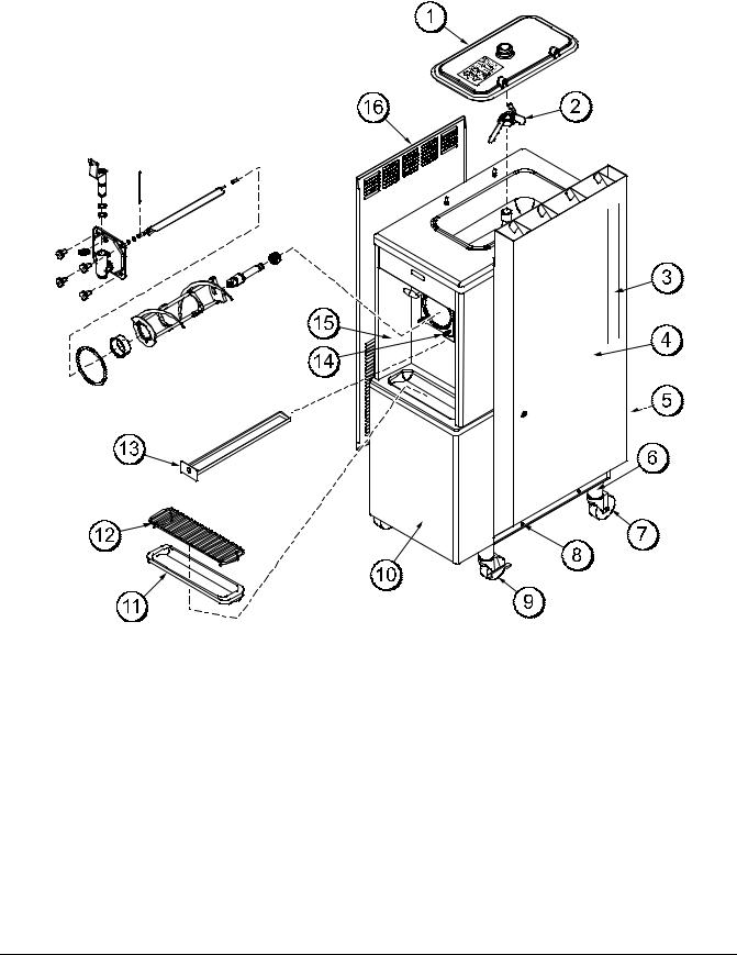
H62 Exploded View
Figure 1
ITEM |
DESCRIPTION |
PART NO. |
|
|
|
1 |
KIT A.-COVER-HOPPER |
X65368 |
|
|
|
2 |
SPACER-PROBE *SQ HOLE* |
030966 |
|
|
|
3 |
DISC-PROBE *SQ HOLE* |
030965 |
|
|
|
4 |
PROBE A.-MIX LOW-HT |
X42077 |
|
|
|
5 |
BLADE A.-AGITATOR |
X56591-SP1 |
|
|
|
6 |
PANEL-REAR |
067501 |
|
|
|
7 |
SCREW-1/4-20X3/8 SLTD |
011694 |
|
|
|
8 |
PANEL A.-DUCT-RIGHT |
X67499-SP1 |
|
|
|
9 |
PANEL-FRONT-UPPER |
067305 |
|
|
|
ITEM |
DESCRIPTION |
PART NO. |
|
|
|
10 |
GASKET-BASE PAN |
067316 |
|
|
|
11 |
SHELF-TRAY-DRIP |
056076 |
|
|
|
12 |
PANEL A.-FRONT-LOWER |
X69419 |
|
|
|
13 |
SHIELD-SPLASH |
049203 |
|
|
|
14 |
TRAY-DRIP |
056858 |
|
|
|
15 |
PANEL-SIDE LEFT |
067500-SP1 |
|
|
|
16 |
PAN-DRIP 11-5/8 LONG |
027503 |
|
|
|
17 |
STUD-NOSE CONE |
011390 |
|
|
|
*18 |
SCREW-10X7/16 UNSLOTTED |
066234 |
|
|
|
*NOT SHOWN
120215
Models H62 & H63 |
7 |
Operator Parts Identification |
|
|
|
H63 Exploded View
Figure 2
ITEM |
DESCRIPTION |
PART NO. |
|
|
|
1 |
KIT A.-COVER-HOPPER |
X65369 |
|
|
|
2 |
BLADE A.-AGITATOR |
X56591-SP1 |
|
|
|
3 |
TRIM-REAR CORNER |
046668 |
|
|
|
4 |
PANEL A.-DUCT-RIGHT |
X67958-SP1 |
|
|
|
5 |
PANEL-REAR W/LOUVERS |
026980-SP |
|
|
|
6 |
ADAPTOR A.-CASTER |
X18915 |
|
|
|
7 |
CASTER-SWV 5/8 STEM 4IN |
018794 |
|
|
|
8 |
SCREW-1/4-20X5/8 |
005542 |
|
|
|
9 |
CASTER-4" SWV 5/8 STEM |
034081 |
|
W/BRAKE |
|
ITEM |
DESCRIPTION |
PART NO. |
|
|
|
10 |
PANEL-SERVICE |
048380 |
|
|
|
11 |
TRAY-DRIP 14.8 |
046275 |
|
|
|
12 |
SHIELD-SPLASH-WIRE |
046177 |
|
13-11/16 L |
|
13 |
PAN-DRIP 19-1/2 LONG |
035034 |
|
|
|
14 |
STUD-NOSE CONE |
011390 |
|
5/16-18X3/8-1 |
|
15 |
PANEL A.-FRONT |
X48371 |
|
|
|
16 |
PANEL-SIDE LEFT |
067721-SP1 |
|
|
|
120214
Operator Parts Identification |
8 |
Models H62 & H63 |
|
|
|
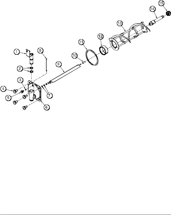
Door and Beater Assembly
Figure 3
ITEM |
DESCRIPTION |
PART NO. |
|
|
|
1 |
VALVE A.--DRAW |
X56119 |
|
|
|
2 |
O--RING--1--1/16 OD X .139W |
020571 |
|
|
|
3 |
O--RING 5/8 OD X .103 W |
016030 |
|
|
|
4 |
NUT--STUD |
021508 |
|
|
|
5 |
PLUG--PRIME |
067192 |
|
|
|
6 |
DOOR A.--1 SPOUT |
X67194--SER |
|
|
|
7 |
O--RING--.291 ID X .080W |
018550 |
|
|
|
8 |
ARM--TORQUE |
067428 |
|
|
|
ITEM |
DESCRIPTION |
PART NO. |
|
|
|
|
|
9 |
TORQUE A.--SOFT SLUSH |
X67190 |
|
|
|
|
|
10 |
BEARING--GUIDE |
014496 |
|
|
|
|
|
11 |
GASKET--DOOR 5.177 ID |
016672 |
|
|
|
|
|
12 |
BEARING--FRONT |
013116 |
|
|
|
|
|
13 |
BEATER A.--7QT BLADELESS |
X45719 |
|
|
|
|
|
14 |
SHAFT--BEATER H62 |
067489 |
|
|
|
||
SHAFT--BEATER H63 |
035527 |
||
|
|||
|
|
|
|
15 |
SEAL--DRIVE SHAFT |
032560 |
|
|
|
|
120214
Models H62 & H63 |
9 |
Operator Parts Identification |
|
|
|
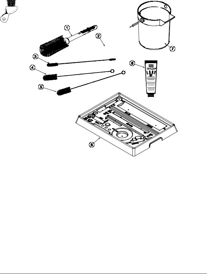
Accessories
Figure 4
ITEM |
DESCRIPTION |
PART NO. |
|
|
|
1 |
BRUSH-MIX PUMP BODY - |
023316 |
|
3” X 7” WHITE |
|
2 |
BRUSH-END-DOOR-SPOUT |
039719 |
|
|
|
3 |
BRUSH-DOUBLE ENDED |
013072 |
|
|
|
4 |
BRUSH-REAR BRG 1IN.D X 2IN |
013071 |
|
|
|
5 |
BRUSH-DRAW VALVE |
014753 |
|
|
|
ITEM |
DESCRIPTION |
PART NO. |
|
|
|
6 |
LUBRICANT-TAYLOR HI PERF |
048232 |
|
|
|
7 |
PAIL-MIX 10 QT. |
013163 |
|
|
|
8 |
TRAY-PARTS-BARREL 7 QT. |
067406 |
|
|
|
* |
KIT A.-TUNE UP |
X67224 |
|
|
|
** |
SANITIZER·STERA SHEEN |
SEE NOTE |
|
|
|
*Not Shown
**Note: A sample container of sanitizer is sent with the unit. For reorders, order Stera Sheen part no. 055492 (100 2 oz. packs) or Kay-5 part no. 041082 (200 packs).
111012
Operator Parts Identification |
10 |
Models H62 & H63 |
|
|
|
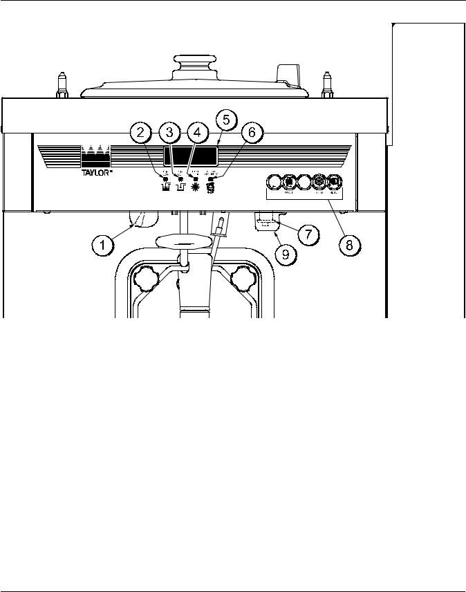
Section 5 |
Important: To the Operator |
H62 |
|
Figure 5
ITEM |
DESCRIPTION |
|
|
1 |
POWER SWITCH (TOGGLE) |
2 |
LED INDICATOR--MIX LOW (PCB A--LED) |
|
|
3 |
LED INDICATOR--MIX OUT (PCB A--LED) |
|
|
4 |
LED INDICATOR--HEAT MODE |
|
|
5 |
LIQUID CRYSTAL DISPLAY |
ITEM |
DESCRIPTION |
|
|
6 |
LED INDICATOR-- CLEAN MANUALLY |
7 |
CONSISTENCY CONTROL |
|
(SWITCH--TORQUE) |
|
|
8 |
KEYPADS |
|
|
9 |
COVER--VISCOSITY ADJUSTMENT |
|
|
120206
Models H62 & H63 |
11 |
Important: To the Operator |
|
|
|
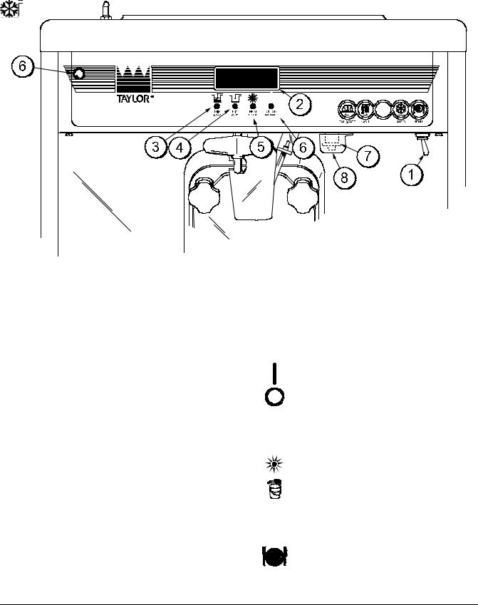
H63
Figure 6
ITEM |
DESCRIPTION |
|
|
1 |
POWER SWITCH (TOGGLE) |
2 |
LIQUID CRYSTAL DISPLAY |
|
|
3 |
LED INDICATOR--MIX LOW (PCB A--LED) |
|
|
4 |
LED INDICATOR--MIX OUT (PCB A--LED) |
|
|
5 |
LED INDICATOR--HEAT MODE |
|
|
6 |
LED INDICATOR--CLEAN MANUALLY |
|
|
7 |
CONSISTENCY CONTROL |
|
(SWITCH--TORQUE) |
|
|
8 |
COVER--VISCOSITY ADJUSTMENT |
|
|
Symbol Definitions
To better communicate in the International arena, the words on many of our operator switches and buttons have symbols to indicate their functions. Your Taylor equipment is designed with these International symbols.
The following chart identifies the symbol definitions used on the operator switches.
= ON
= OFF
= MIX LOW
= MIX OUT
= HEAT MODE
= CLEAN MANUALLY = WASH
= AUTO
= MENU
120206
Important: To the Operator |
12 |
Models H62 & H63 |
|
|
|

Power Switch
When placed in the ON position, the power switch allows control panel operation. The power switch is located on the left side of the control channel.
Liquid Crystal Display
The Liquid Crystal Display (LCD) is located on the front control panel. The LCD is used to show the current mode of operation, and whether or not there is sufficient mix.
LED Indicator - MIX LOW
The MIX LOW indicator flashes to indicate that the mix hopper has a low supply of mix. The mix hopper should be filled as soon as possible.
LED Indicator - CLEAN MANUALLY
The CLEAN MANUALLY indicator flashes to indicate that the freezer must be disassembled and brush cleaned within 24 hours.
When all four indicators are flashing, the freezer is in a locked condition. Once a hard lock condition has been remedied, two indicators will remain flashing until the mix low and mix out conditions have been satisfied. During a soft lock condition, all four indicators will stop flashing once the unit has been placed in a heat cycle.
Consistency Control
The viscosity (thickness) of the shake is controlled by a sensing device called the consistency control. The consistency control knob is located to the lower right of the control channel. To achieve a thicker shake, turn the knob clockwise and counterclockwise to achieve a thinner shake consistency.
Allow the refrigeration system to cycle on and off 2 or 3 times before an accurate consistency can be evaluated.
LED Indicator - MIX OUT
The MIX OUT indicator flashes to indicate that the mix hopper has an insufficient supply of mix to operate the freezer. At this time, the AUTO mode is locked out and the freezer goes into the STANDBY mode. To return the freezer to the AUTO mode, fill the hopper with mix and press the AUTO key. The freezer will automatically begin operation.
LED Indicator - HEAT MODE
The HEAT MODE indicator flashes to indicate that the freezer is in the process of a heat cycle.
Reset Mechanism
The reset button is located in the left side panel of the H62. The reset button is located in the right side panel of the H63. The reset mechanism protects the beater motor from an overload condition. If an overload occurs, the reset mechanism will trip. To properly reset the freezer, press the reset button firmly and clear the tone per instructions in “Clearing Fault Tones” on page 18.
If the reset mechanism trips again, contact your authorized Taylor Distributor to resolve the problem.
 Warning: Do not use metal objects to press the reset button. Failure to comply may result in severe personal injury or death.
Models H62 & H63 |
13 |
Important: To the Operator |
|
|
|

Operating Screen Descriptions
When the machine is powered the system will initialize. The screen will display “INITIALIZING”. There will be four types of data the system will check: LANGUAGE, SYSTEM DATA, CONFIG DATA, and LOCKOUT DATA. During the INITIALIZING... LANGUAGE screen, the alarm will be on. If the system data, configuration data, or lockout history data has become corrupt, the following screen will alert the operator that the system settings may have been changed.
NVRAM FAULT
RESET TO DEFAULTS
PRESS SEL KEY
Once the system has initialized the SAFETY TIMEOUT screen is displayed and the alarm is turned on.
SAFETY TIMEOUT
ANY KEY ABORTS
This screen will be displayed, with the alarm on, for 60 seconds or until any key is pressed.
After the safety timeout has been completed, and the power switch is OFF, one of the following screens is displayed.
The first screen is displayed if the machine is not in a brush clean state.
POWER SWITCH OFF
MIX: OUT TIME: 4:30
HOPPER: 62.1
BARREL: 67.7
If any of the requirements for a brush clean have not been met, the time displayed will remain at 5:00 minutes. When all the requirements for a brush cleaning are met, and the five minutes expire, the screen will change to the second screen, which is the standard power switch OFF screen.
POWER SWITCH OFF
-= - = - = - = - = - UNIT CLEANED
When the power switch is set in the ON position, the system mode of operation screen is displayed. In this example, the machine is ON, but no mode of operation has been selected. The second line of the display indicates whether there is a sufficient supply of mix in the hopper or if there is a LOW or OUT mix condition. The third line of the display shows the temperature of the mix hopper. After pressing the AUTO key, the last line of the display shows the month and date (MM = month, DD = day) that the machine needs to be disassembled and brush cleaned.
MODE: ON
MIX: OK
HOPPER TEMP: 40.0F
BRUSH CLEAN ON: MM/DD
The next display indicates the freezer is operating in two different modes. The following information is given:
The machine is operating in the WASH mode and the mix level in the hopper is low. The temperature of the mix hopper is 40_F (4.4_C), and the machine needs to be brush cleaned on October 31st.
MODE: WASH
MIX: LOW
HOPPER TEMP: 40.0 F
BRUSH CLEAN ON: 10/31
Important: To the Operator |
14 |
Models H62 & H63 |
|
|
|
 Loading...