


SERVICE
MANUAL
Model 358 & 359
Thick Shake Dessert Machines
Service Manual
056788-S |
8/27/10 (Original Publication) |
|
(Updated 2/19/14) |

Table of Contents
Section 1: Introduction . . . . . . . . . . . . . . . . . . . . . . . . . . . . . . . . . . . . . . . . . . . . . . . |
1 |
Safety . . . . . . . . . . . . . . . . . . . . . . . . . . . . . . . . . . . . . . . . . . . . . . . . . . . . . . . . . . . . . |
2 |
Model 358 Specifications . . . . . . . . . . . . . . . . . . . . . . . . . . . . . . . . . . . . . . . . . . . . . |
4 |
Model 359 Specifications . . . . . . . . . . . . . . . . . . . . . . . . . . . . . . . . . . . . . . . . . . . . . |
5 |
Running Specifications . . . . . . . . . . . . . . . . . . . . . . . . . . . . . . . . . . . . . . . . . . . . . . . |
6 |
General Installation Instructions . . . . . . . . . . . . . . . . . . . . . . . . . . . . . . . . . . . . . . . |
7 |
Refrigerant . . . . . . . . . . . . . . . . . . . . . . . . . . . . . . . . . . . . . . . . . . . . . . . . . . . . . . . . . |
9 |
Environmental Notices . . . . . . . . . . . . . . . . . . . . . . . . . . . . . . . . . . . . . . . . . . . . . . . |
10 |
Section 2: Controls & Systems . . . . . . . . . . . . . . . . . . . . . . . . . . . . . . . . . . . . . . . . |
11 |
Thermistor Control . . . . . . . . . . . . . . . . . . . . . . . . . . . . . . . . . . . . . . . . . . . . . . . . . . |
12 |
Thermistor Curve . . . . . . . . . . . . . . . . . . . . . . . . . . . . . . . . . . . . . . . . . . . . . . . . . . . |
14 |
Refrigeration System . . . . . . . . . . . . . . . . . . . . . . . . . . . . . . . . . . . . . . . . . . . . . . . . |
15 |
Maintaining Quality . . . . . . . . . . . . . . . . . . . . . . . . . . . . . . . . . . . . . . . . . . . . . . . . . . |
16 |
Section 3: Troubleshooting . . . . . . . . . . . . . . . . . . . . . . . . . . . . . . . . . . . . . . . . . . . |
17 |
Troubleshooting Thermistor Components . . . . . . . . . . . . . . . . . . . . . . . . . . . . . . |
18 |
General Troubleshooting Guide . . . . . . . . . . . . . . . . . . . . . . . . . . . . . . . . . . . . . . . |
19 |
Overrun . . . . . . . . . . . . . . . . . . . . . . . . . . . . . . . . . . . . . . . . . . . . . . . . . . . . . . . . . . . . |
22 |
Section 4: General Service . . . . . . . . . . . . . . . . . . . . . . . . . . . . . . . . . . . . . . . . . . . . |
23 |
Evaporator Oil . . . . . . . . . . . . . . . . . . . . . . . . . . . . . . . . . . . . . . . . . . . . . . . . . . . . . . |
24 |
Rear Bearing Unit Alignment . . . . . . . . . . . . . . . . . . . . . . . . . . . . . . . . . . . . . . . . . . |
25 |
Pulley Alignment . . . . . . . . . . . . . . . . . . . . . . . . . . . . . . . . . . . . . . . . . . . . . . . . . . . . |
26 |
Rear Shell Bearing . . . . . . . . . . . . . . . . . . . . . . . . . . . . . . . . . . . . . . . . . . . . . . . . . . |
26 |
Beater Shaft Removal . . . . . . . . . . . . . . . . . . . . . . . . . . . . . . . . . . . . . . . . . . . . . . . |
26 |
Preventative Maintenance . . . . . . . . . . . . . . . . . . . . . . . . . . . . . . . . . . . . . . . . . . . . |
27 |
Models 358 & 359 |
Table of Contents |
|
|

Table of Contents - Page 2
Section 5: Parts . . . . . . . . . . . . . . . . . . . . . . . . . . . . . . . . . . . . . . . . . . . . . . . . . . . . . . |
29 |
Parts Warranty Explanation . . . . . . . . . . . . . . . . . . . . . . . . . . . . . . . . . . . . . . . . . . . |
30 |
Model 358 Operator Parts . . . . . . . . . . . . . . . . . . . . . . . . . . . . . . . . . . . . . . . . . . . . |
31 |
Model 358 Exploded View . . . . . . . . . . . . . . . . . . . . . . . . . . . . . . . . . . . . . . . . . . . . |
32 |
Model 358 Shell Assembly . . . . . . . . . . . . . . . . . . . . . . . . . . . . . . . . . . . . . . . . . . . |
34 |
Model 358 Control A. (X66731-33) . . . . . . . . . . . . . . . . . . . . . . . . . . . . . . . . . . . . |
35 |
Model 358 Channel A.-Control (X63534) . . . . . . . . . . . . . . . . . . . . . . . . . . . . . . . |
36 |
Models 358 & 359 Beater Door Assembly . . . . . . . . . . . . . . . . . . . . . . . . . . . . . . |
38 |
Model 359 Operator Parts . . . . . . . . . . . . . . . . . . . . . . . . . . . . . . . . . . . . . . . . . . . . |
39 |
Model 359 Exploded View . . . . . . . . . . . . . . . . . . . . . . . . . . . . . . . . . . . . . . . . . . . . |
40 |
Model 359 Shell Assembly . . . . . . . . . . . . . . . . . . . . . . . . . . . . . . . . . . . . . . . . . . . |
42 |
Model 359 Channel A.-Control (X65222) . . . . . . . . . . . . . . . . . . . . . . . . . . . . . . . |
43 |
Model 359 Control A. (X65279-33) . . . . . . . . . . . . . . . . . . . . . . . . . . . . . . . . . . . . |
44 |
Models 358 & 359 Switch A.-Draw (X65212-SER) . . . . . . . . . . . . . . . . . . . . . . . |
45 |
Models 358 & 359 Accessories . . . . . . . . . . . . . . . . . . . . . . . . . . . . . . . . . . . . . . . |
46 |
Parts List . . . . . . . . . . . . . . . . . . . . . . . . . . . . . . . . . . . . . . . . . . . . . . . . . . . . . . . . . . . |
47 |
Wiring Diagrams . . . . . . . . . . . . . . . . . . . . . . . . . . . . . . . . . . . . . . . . . . . . . . . . . . . . |
54 |
CAUTION: Information in this manual is intended to be used by Taylor Authorized Service Technicians only.
Note: Continuing research results in steady improvements; therefore, information in this manual is subject to change without notice.
E August, 2010 Taylor (Original Publication) (Updated March, 2011)
All rights reserved. 056788-S
The word Taylor and the Crown design
are registered trademarks in the United States of America and certain other countries.
Taylor Company
750 N. Blackhawk Blvd.
Rockton, IL 61072
Table of Contents |
Models 358 & 359 |
|
|

Section 1: Introduction
S Safety
S Specifications
S Running Specifications
S General Installation Instructions
S Refrigerant
S Environmental Notices
Models 358 & 359 |
1 |
Introduction |
Safety
______________________________
We, at Taylor Company, are deeply committed to manufacturing safe operating and serviceable equipment. The many built-in safety features that are part of all Taylor equipment are aimed at protecting operators and trained service technicians alike.
 This manual is intended exclusively for Taylor Company authorized service personnel.
 DO NOT attempt to run the equipment unless you have been properly trained to do so. Failure to follow this instruction may result in equipment damage, poor equipment performance, health hazards, or personal injury.
 CAUTION: THIS EQUIPMENT MUST BE PROPERLY GROUNDED! Do not operate this unit unless it is properly grounded and all service panels and access doors are restrained with screws. Failure to do so can result in severe personal injury from electrical shock!
SDO NOT attempt any repairs unless the main power supply to the unit has been disconnected.
SDO NOT operate the unit with larger fuses than specified on the data label.
SStationary appliances which are not equipped with a power cord and a plug or other device to disconnect the appliance from the power source must have an all-pole disconnecting device with a contact gap of at least 3 mm installed in the external installation.
SAppliances that are permanently connected to fixed wiring and for which leakage currents may exceed 10 mA, particularly when disconnected, not used for long periods, or during initial installation, shall have protective devices such as a GFI to
protect against the leakage of current, and be installed by authorized personnel to the local codes.
SSupply cords used with this unit shall be oil-resistant, sheathed flexible cable, not lighter than ordinary polychloroprene or other equivalent synthetic elastomer-sheathed cord, (Code designation 60245 IEC 57) installed with the proper cord anchorage to relieve conductors from strain, including twisting, at the terminals and protect the insulation of the conductors from abrasion.
Failure to follow these instructions may result in electrocution or damage to the unit.
 This unit is provided with an equipotential grounding lug that is to be properly attached to either the rear of the frame or the under side of the base pan near the entry hole for incoming power, by the authorized installer. The installation location is marked by the equipotential bonding symbol (5021 of IEC 60417-1) on both the removable panel and the equipment's frame, as well as on the diagram.
DO NOT remove the freezer door or any internal operating parts (examples: beater, scraper blades, etc.) unless all control switches are in the OFF position. Failure to follow these instructions may result in severe personal injury from hazardous moving parts.
 THIS UNIT HAS MANY SHARP EDGES THAT CAN CAUSE SEVERE INJURIES.
 This unit must be installed on a level surface to avoid the hazard of tipping. Extreme care should be taken in moving this equipment for any reason.
Two or more people are required to safely move this unit. Failure to comply may result in personal injury or equipment damage.
Introduction |
2 |
Models 358 & 359 |

 This unit must NOT be installed in an area where a water jet or hose can be used. NEVER use a water jet or hose to rinse or clean this unit. Using a water jet or hose on or around this equipment may result in the electrocution of the user or damage to the equipment.
 Cleaning and sanitizing schedules are governed by your state or local regulatory agencies and must be followed accordingly. Please refer to the cleaning section of the Operator Manual for the proper procedure to clean this unit.
Models 358 & 359 |
3 |
Introduction |
Model 358 Specifications
SFreezing Cylinder - One; 7 quart (6.6 liter) capacity.
SMix Hopper - One; 20 quart (18.9 liter) capacity. Refrigerated and insulated.
S Beater Motor - One; 1.5 hp.
SRefrigeration Unit - One; approximately 9,500 btu/hr compressor. Refrigerant 404A.
SElectrical - Standard is 208/230-60-3; however, other electrical characteristics are available. Each unit requires electrical service.*
Three Phase Maximum Fuse Size: 20A Minimum Circuit Ampacity: 16A
*For exact electrical information, always refer to the data label of the unit.
SAir Cooled - Clearance: 3” (76 mm) around all sides.
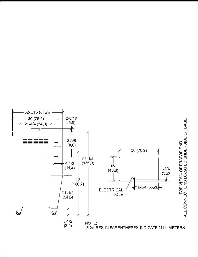
SDimensions -
Width: 16” (406 mm) Depth: 30” (762 mm) Height: 55-7/8” (1418 mm)
Floor Clearance: 3-1/2” (89 mm) mounted on standard casters.
SApproximate Weights -
Net: 356 lbs. (161.5 kgs.) Crated: 400 lbs. (181.4 kgs.) Volume: 22.3 cu. ft. (.63 cu. m.)
Availability and specifications subject to change without notice.
Figure 1
Introduction |
4 |
Models 358 & 359 |

Model 359 Specifications
SFreezing Cylinder - Two; 7 quart (6.6 liter) capacity.
SMix Hopper - Two; 20 quart (18.9 liter) capacity. Refrigerated and insulated.
S Beater Motor - Two; 1.5 hp.
SRefrigeration Unit - Two; approximately 9,500 btu/hr compressors. Refrigerant 404A.
SElectrical - Standard is 208/230-60-3; however, other electrical characteristics are available.
Each unit requires electrical service.* Maximum Fuse Size: 35A
Minimum Circuit Ampacity: 30A
*For exact electrical information, always refer to the data label of the unit.
SAir Cooled - Clearance: 3” (76 mm) around all sides.
SDimensions -
Width: 26” (660 mm) Depth: 32-3/8” (822 mm) Height: 55-7/8” (1418 mm)
Floor Clearance: 4-1/4” (108 mm) mounted on standard casters.
SApproximate Weights -
Net: 580 lbs. (263.1 kgs.) Crated: 673 lbs. (305.3 kgs.) Volume: 41.1 cu. ft. (1.16 cu. m.)
Availability and specifications subject to change without notice.
|
Figure 2 |
|
|
|
140219 |
Models 358 & 359 |
5 |
Introduction |

Running Specifications
Expansion Valve Setting
404A/HP62: 20 - 22 PSI (138 - 152 kPa)
Low Side Pressure
Low side pressure = expansion valve setting
To adjust the low side pressure, place the gauge on the low side suction port at the compressor. With the compressor running, turn the adjustment knob of the automatic expansion valve clockwise to raise the low side pressure and counterclockwise to lower the pressure.
High Side Pressure
Air Cooled: The following chart indicates normal operating head pressures at various ambient temperatures:
Ambient Temperature |
Normal Operating Head |
|
|
|
Pressures |
|
|
|
F |
C |
PSI |
|
|
|
70_ |
21.1_ |
240 -- 270 |
|
|
(1,655 -- 1,862 kPa) |
|
|
|
80_ |
26.7_ |
270 -- 300 |
|
|
(1,862 -- 2,069 kPa) |
|
|
|
90_ |
32.2_ |
300 -- 340 |
|
|
(2,069 -- 2,344 kPa) |
|
|
|
100_ |
37.8_ |
340 -- 380 |
|
|
(2,344 -- 2,620 kPa) |
|
|
|
Water Cooled: The high side pressure for water cooled units is determined by the water valve. The water valve is factory set to maintain a high pressure of 235 PSI (1,620 kPa). To adjust the high pressure, place the gauge on the high side access port. Turn the adjustment knob on the water valve clockwise to lower the high side pressure and counterclockwise to raise the pressure.
The high side pressure switch is factory set at 440 PSI (3,034kPa) for 404A/HP62. In the event of a water loss, this switch will sense a rise in pressure and deactivate the unit.
EPR Valve Setting
The product temperature in the mix hopper is maintained by the main refrigeration system and can be adjusted by the EPR (evaporator pressure regulator) valve. The EPR valve is factory set at 67 - 69 PSI (462 - 476 kPa) in order to maintain hopper product temperature below 40_F (4_C). To adjust the hopper temperature, place the gauge on the access port at the inlet of the EPR valve. With the compressor running, loosen the locking nut and turn the adjustment screw (located on the top of the valve) clockwise to raise hopper temperature and counterclockwise to lower the temperature. When the adjustment is complete, tighten the locking nut.
Introduction |
6 |
Models 358 & 359 |
General Installation Instructions
CAUTION: Only trained, authorized service technicians should install this equipment. Failure to comply will void the factory warranty.
The following are general installation instructions. For complete installation details, please see the checkout card.
 ALL WIRING AND PLUMBING MUST CONFORM TO NATIONAL AND LOCAL CODES.
INSTALL POTABLE WATER CONNECTION WITH ADEQUATE BACK-FLOW PROTECTION TO COMPLY WITH APPLICABLE NATIONAL, STATE AND LOCAL CODES.
Site Preparation
Review the area the unit is to be installed in before uncrating the unit. Make sure that all possible hazards to the user and the equipment have been addressed.
Clearance: Air Cooled Units
Air cooled units require a minimum of 3” (76 mm) of clearance around all sides of the unit. Failure to allow for adequate clearance can reduce the refrigeration capacity of the unit and possibly cause damage to the compressor.
For Indoor Use Only: This unit is designed to operate indoors, under normal ambient temperatures of 70_ - 75_F (21_ - 24_C). The machine has successfully performed in high ambient temperatures of 104_(40_C) at reduced capacities.
 This unit must NOT be installed in an area where a water jet or hose can be used. NEVER use a water jet or hose to rinse or clean this unit. Using a water jet or hose on or around this equipment may result in the electrocution of the user or damage to the equipment.
 This unit must be installed on a level surface to avoid the hazard of tipping. Extreme care should be taken in moving this equipment for any reason.
Two or more people are required to safely move this unit. Failure to comply may result in personal injury or equipment damage.
Uncrate the machine. Inspect the unit for damage. Report any damage to the Taylor factory immediately.
This piece of equipment is made in the USA and has USA sizes of hardware. All metric conversions are approximate and vary in size.
Installer Safety
 In all areas of the world, equipment should be installed in accordance with existing local codes. Please contact your local authorities if you have any questions.
Care should be taken to ensure that all basic safety practices are followed during the installation and servicing activities related to the installation and service of Taylor equipment.
SOnly authorized Taylor service personnel should perform installation and repairs on the equipment.
SAuthorized service personnel should consult OSHA Standard 29CFRI910.147 or the applicable code of the local area for the industry standards on lockout/tagout procedures before beginning any installation or repairs.
SAuthorized service personnel must ensure that the proper PPE (Personal Protective Equipment) is available and worn when required during installation and service.
SAuthorized service personnel must remove all metal jewelry, rings, and watches before working on electrical equipment.
 THIS UNIT HAS MANY SHARP EDGES THAT CAN CAUSE SEVERE INJURIES.
Models 358 & 359 |
7 |
Introduction |
Electrical Connections
 In the United States, this equipment is intended to be installed in accordance with the National Electrical Code (NEC), ANSI/NFPA 70-1987. The purpose of the NEC code is the practical safeguarding of persons and property from hazards arising from the use of electricity. This code contains provisions considered necessary for safety.
In all other areas of the world, equipment should be installed in accordance with the existing local codes. Please contact your local authorities.
Each machine requires one power supply. Check the data label on the machine for fuse, circuit ampacity and other electrical specifications. Refer to the wiring diagram provided inside the control box for proper power connections.
It is recommended that the machine be plugged into an electrical surge protector for added protection against power surges which could damage an electrical/electronics component. An electrical surge event may cause the unit to shut down. Such an event would require service by a qualified service technician if the machine was not adequately protected. A good surge protector, as would normally be used on a home computer, should be adequate. They are available at most computer retail outlets or electrical supply stores.
FOLLOW YOUR LOCAL ELECTRICAL CODES!
 CAUTION: THIS EQUIPMENT MUST BE PROPERLY GROUNDED! FAILURE TO DO SO CAN RESULT IN SEVERE PERSONAL INJURY FROM ELECTRICAL SHOCK!
 Note: This unit is provided with an equipotential grounding lug that is to be properly attached to either the rear of the frame or the under side of the base pan near the entry hole for incoming power, by the authorized installer. The installation location is marked by the equipotential bonding symbol (5021 of IEC 60417-1) on both the removable panel and the equipment's frame, as well as on the diagram.
SDO NOT operate the machine with larger fuses than specified on the data label.
SStationary appliances which are not equipped with a power cord and a plug or another device to disconnect the appliance from the power source must have an all-pole disconnecting device with a contact gap of at least 3 mm installed in the external installation.
SAppliances that are permanently connected to fixed wiring and for which leakage currents may exceed 10 mA, particularly when disconnected, not used for long periods, or during initial installation, shall have protective devices such as a GFI to protect against the leakage of current, and be installed by authorized personnel to the local codes.
SSupply cords used with this unit shall be oil-resistant, sheathed flexible cable, not lighter than ordinary polychloroprene or other equivalent synthetic elastomer-sheathed cord (Code designation 60245 IEC 57) installed with the proper cord anchorage to relieve conductors from strain, including twisting, at the terminals and protect the insulation of the conductors from abrasion.
Failure to follow these instructions may result in electrocution or damage to the machine.
Introduction |
8 |
Models 358 & 359 |

Refrigerant
______________________________
In consideration of our environment, Taylor proudly uses only earth friendly HFC refrigerants. The HFC refrigerant used in this unit is R404A. This refrigerant is generally considered non-toxic and non-flammable, with an Ozone Depleting Potential (ODP) of zero (0).
However, any gas under pressure is potentially hazardous and must be handled with caution.
NEVER fill any refrigerant cylinder completely with liquid. Filling the cylinder to approximately 80% will allow for normal expansion.
 Refrigerant liquid sprayed onto the skin may cause serious damage to tissue. Keep eyes and skin protected. If refrigerant burns should occur, flush immediately with cold water. If burns are severe, apply ice packs and contact a physician immediately.
 Taylor reminds technicians to be cautious of government laws regarding refrigerant recovery, recycling, and reclaiming systems. If you have any questions regarding these laws, please contact the factory Service Department.
 WARNING: R404A refrigerant used in conjunction with polyolester oils is extremely moisture absorbent. When opening a refrigeration system, the maximum time the system is open must not exceed 15 minutes. Cap all open tubing to prevent humid air or water from being absorbed by the oil.
Compressor Warranty Disclaimer
The refrigeration compressor(s) on this machine are warranted for the term indicated on the warranty card accompanying this machine. However, due to the Montreal Protocol and the U.S. Clean Air Act Amendments of 1990, many new refrigerants are being tested and developed; thus seeking their way into the service industry. Some of these new refrigerants are being advertised as drop-in replacements for numerous applications. It should be noted that in the event of ordinary service to this machine's refrigeration system, only the refrigerant specified on the affixed data label should be used. The unauthorized use of alternate refrigerants will void your compressor warranty. It will be the owners' responsibility to make this fact known to any technicians they employ.
It should be noted that Taylor does not warrant the refrigerant used in its equipment. For example, if the refrigerant is lost during the course of ordinary service to this machine, Taylor has no obligation to either supply or provide its replacement, either at billable or unbillable terms. Taylor does have the obligation to recommend a suitable replacement if the original refrigerant is banned, obsoleted, or no longer available during the five year warranty of the compressor.
Taylor will continue to monitor the industry and test new alternate refrigerants as they are being developed. Should a new alternate prove, through our testing, that it would be accepted as a drop-in replacement, then the above disclaimer would become null and void. To find out the current status of an alternate refrigerant as it relates to your compressor, call the local Taylor Distributor or the Taylor Factory. Be prepared to provide the model/serial number of the unit in question.
Models 358 & 359 |
9 |
Introduction |

Environmental Notices
______________________________
In consideration of our environment, Taylor proudly uses only earth friendly HFC refrigerants. The HFC refrigerant used in this unit is R404A. This refrigerant is generally considered non-toxic and non-flammable, with an Ozone Depleting Potential (ODP) of zero (0).
However, any gas under pressure is potentially hazardous and must be handled with caution.
 If the crossed out wheeled bin symbol is affixed to this product, it signifies that this product is compliant with the EU Directive as well as other similar legislation in effect after August 13, 2005. Therefore, it must be collected separately after its use is completed, and cannot be disposed as unsorted municipal waste.
The user is responsible for returning the product to the appropriate collection facility, as specified by your local code.
For additional information regarding applicable local laws, please contact the municipal facility and/or local distributor.
NOISE LEVEL: Airborne noise emission does not exceed 78 dB(A) when measured at a distance of 1.0 meter from the surface of the machine and at a height of 1.6 meters from the floor.
Introduction |
10 |
Models 358 & 359 |

Section 2: Controls & Systems
S Thermistor Control
S Thermistor Curve
S Refrigeration System
S Maintaining Quality
Models 358 & 359 |
11 |
Controls & Systems |

Thermistor Control
Function
The thermistor control maintains product temperature in the freezing cylinder by monitoring the resistance of the thermistor probe.
Thermistor Probe (038061-20)
The resistance value of the thermistor probe corresponds with the product temperature in the freezing cylinder. As the product becomes colder, the probe resistance increases. As the product becomes warmer, the probe resistance decreases.
Approximate probe resistance readings:
S10,000 OHMS at room temperature (77°F/25°C)
S46,012 OHMS at product temperature (20°F/-6.6°C)
Operation
The thermistor probe is positioned in the bulb-well located at the front of the freezing cylinder. The thermistor control becomes operational when powered by the 24 VAC transformer.
When the desired product is achieved (control set-point), the thermistor control relay relaxes and discontinues sending L1 power to the compressor relay coil.
When the product in the freezing cylinder warms up
.5°F (.3°C) above the control set-point, the thermistor control relay closes, sending L1 power to the compressor relay coil. The refrigeration system will run until the control set-point is achieved.
Anticipator
The anticipator signals the thermistor control to activate the refrigeration system whenever product is drawn. As the draw valve is raised and the freezer draw switch closes, continuity is created between the thermistor control anticipator terminals. The thermistor control relay will close within .5 seconds to start the refrigeration system. The control set point will shift 8°F (4.4°C) approximately 5 seconds after the draw switch is released. The set point shift will change 3.5°F (2°C) and remain in that state for 20 seconds. The set point will then return to its original setting.
Setting Temperature
1.Position the thermistor fine adjustment at mid-range. This will limit the fine adjustment temperature range to ±2_F (±1_C).
2.Turn the coarse adjustment clockwise to the coldest setting.
3.With the freezer correctly primed, place the power switch in the “AUTO” position.
4.After the appropriate freezing time, test the product temperature. When a sample portion temperature is approximately 1_ above the desired temperature setting, slowly turn the coarse adjustment counterclockwise (warmer) until the refrigeration system cycles off.
5.Allow the refrigeration system to cycle through at least two “off” cycles. After the unit cycles off, draw a sample of product and check the temperature. Readjust the coarse adjustment as required, but make only small adjustments.
Note: The anticipator automatically activates the refrigeration system within 5 seconds after the draw valve is opened. If several small samples are drawn, the temperature may drift lower. To accurately set the control, let the product temperature stabilize by allowing the thermistor control to cycle the freezer on and off by the control set-point, not the anticipator.
Controls & Systems |
12 |
Models 358 & 359 |

Service Tips
If a problem arises with the thermistor control assembly, identify and replace only the faulty component. For example, if the probe is defective, replace only the probe.
SA varistor must be connected to the thermistor control 24 VAC terminals in order to protect the control from voltage spikes (varistor part number X31547).
SFill the bulb-well with antifreeze before installing the thermistor probe.
SBe sure the probe is installed completely into the bottom of the bulb-well.
Note: Lower the probe to the point where the wires extend from the probe and a resistance is felt. This indicates the probe is installed completely in the bottom of the bulb-well.
If the thermistor relay which starts the compressor will not close, check the following items:
ELECTRICAL SHOCK AREA! USE CAUTION!
1.Make sure power is being supplied to the freezer and that all operating switches are in the correct position.
2.Using a voltmeter, check the voltage supply to the thermistor control. The control requires 24 volts to operate.
3.Using an ohmmeter, check probe resistance. (Refer to the thermistor curve chart on page 14 for proper readings.)
If the thermistor relay which deactivates the compressor will not open, check the following items:
ELECTRICAL SHOCK AREA! USE CAUTION!
1.Make sure the thermistor relay opens when the freezer control switch is in the “OFF” position.
2.Make sure the thermistor probe is connected to the correct probe terminals.
3.Using an ohmmeter, check the thermistor probe for proper resistance. (Refer to the thermistor curve chart on page 14 for proper readings.)
4.Disconnect one wire to an anticipator terminal. If the thermistor relay opens after approximately 25 seconds, the problem is in the anticipator wiring circuit.
When problems such as erratic product quality occur, it is of utmost importance to determine if the thermistor components are defective before replacing them.
For a diagram of the thermistor control, see page 18 (Troubleshooting Thermistor Components).
Models 358 & 359 |
13 |
Controls & Systems |

Thermistor Curve
F |
C |
K OHM |
|
F |
C |
K OHM |
|
F |
C |
K OHM |
|
|
|
|
|
|
|
|
|
|
|
-10 |
-23.3 |
118.201 |
|
22 |
-5.5 |
43.530 |
|
54 |
12.2 |
17.915 |
|
|
|
|
|
|
|
|
|
|
|
-9 |
-22.7 |
114.394 |
|
23 |
-5.0 |
42.340 |
|
55 |
12.7 |
17.451 |
|
|
|
|
|
|
|
|
|
|
|
-8 |
-22.2 |
110.709 |
|
24 |
-4.4 |
41.136 |
|
56 |
13.3 |
16.998 |
|
|
|
|
|
|
|
|
|
|
|
-7 |
-21.6 |
107.143 |
|
25 |
-3.8 |
39.967 |
|
57 |
13.8 |
16.557 |
|
|
|
|
|
|
|
|
|
|
|
-6 |
-21.1 |
103.692 |
|
26 |
-3.3 |
38.830 |
|
58 |
14.4 |
16.128 |
|
|
|
|
|
|
|
|
|
|
|
-5 |
-20.5 |
100.352 |
|
27 |
-2.7 |
37.727 |
|
59 |
15.0 |
15.710 |
|
|
|
|
|
|
|
|
|
|
|
-4 |
-20.0 |
97.120 |
|
28 |
-2.2 |
36.654 |
|
60 |
15.5 |
15.315 |
|
|
|
|
|
|
|
|
|
|
|
-3 |
-19.4 |
94.085 |
|
29 |
-1.6 |
35.612 |
|
61 |
16.1 |
14.929 |
|
|
|
|
|
|
|
|
|
|
|
-2 |
-18.8 |
91.144 |
|
30 |
-1.1 |
34.599 |
|
62 |
16.6 |
14.554 |
|
|
|
|
|
|
|
|
|
|
|
-1 |
-18.3 |
88.296 |
|
31 |
-0.5 |
33.616 |
|
63 |
17.2 |
14.187 |
|
|
|
|
|
|
|
|
|
|
|
0 |
-17.7 |
85.536 |
|
32 |
0 |
32.660 |
|
64 |
17.7 |
13.830 |
|
|
|
|
|
|
|
|
|
|
|
1 |
-17.2 |
82.863 |
|
33 |
0.5 |
31.760 |
|
65 |
18.3 |
13.482 |
|
|
|
|
|
|
|
|
|
|
|
2 |
-16.6 |
80.273 |
|
34 |
1.1 |
30.885 |
|
66 |
18.8 |
13.143 |
|
|
|
|
|
|
|
|
|
|
|
3 |
-16.1 |
77.765 |
|
35 |
1.6 |
30.035 |
|
67 |
19.4 |
12.812 |
|
|
|
|
|
|
|
|
|
|
|
4 |
-15.5 |
75.334 |
|
36 |
2.2 |
29.207 |
|
68 |
20.0 |
12.490 |
|
|
|
|
|
|
|
|
|
|
|
5 |
-15.0 |
72.980 |
|
37 |
2.7 |
28.403 |
|
69 |
20.5 |
12.185 |
|
|
|
|
|
|
|
|
|
|
|
6 |
-14.4 |
70.627 |
|
38 |
3.3 |
27.620 |
|
70 |
21.1 |
11.888 |
|
|
|
|
|
|
|
|
|
|
|
7 |
-13.8 |
68.350 |
|
39 |
3.8 |
26.859 |
|
71 |
21.6 |
11.598 |
|
|
|
|
|
|
|
|
|
|
|
8 |
-13.3 |
66.147 |
|
40 |
4.4 |
26.120 |
|
72 |
22.2 |
11.315 |
|
|
|
|
|
|
|
|
|
|
|
9 |
-12.7 |
64.014 |
|
41 |
5.0 |
25.400 |
|
73 |
22.7 |
11.039 |
|
|
|
|
|
|
|
|
|
|
|
10 |
-12.2 |
61.951 |
|
42 |
5.5 |
24.721 |
|
74 |
23.3 |
10.769 |
|
|
|
|
|
|
|
|
|
|
|
11 |
-11.6 |
59.953 |
|
43 |
6.1 |
24.059 |
|
75 |
23.8 |
10.507 |
|
|
|
|
|
|
|
|
|
|
|
12 |
-11.1 |
58.021 |
|
44 |
6.6 |
23.416 |
|
76 |
24.4 |
10.250 |
|
|
|
|
|
|
|
|
|
|
|
13 |
-10.5 |
56.150 |
|
45 |
7.2 |
22.789 |
|
77 |
25.0 |
10.000 |
|
|
|
|
|
|
|
|
|
|
|
14 |
-10.0 |
54.340 |
|
46 |
7.7 |
22.180 |
|
78 |
25.5 |
9.763 |
|
|
|
|
|
|
|
|
|
|
|
15 |
-9.4 |
52.854 |
|
47 |
8.3 |
21.586 |
|
79 |
26.1 |
9.532 |
|
|
|
|
|
|
|
|
|
|
|
16 |
-8.8 |
51.409 |
|
48 |
8.8 |
21.009 |
|
80 |
26.6 |
9.306 |
|
|
|
|
|
|
|
|
|
|
|
17 |
-8.3 |
50.003 |
|
49 |
9.4 |
20.447 |
|
81 |
27.2 |
9.085 |
|
|
|
|
|
|
|
|
|
|
|
18 |
-7.7 |
48.636 |
|
50 |
10.0 |
19.900 |
|
82 |
27.7 |
8.870 |
|
|
|
|
|
|
|
|
|
|
|
19 |
-7.2 |
47.306 |
|
51 |
10.5 |
19.384 |
|
83 |
28.3 |
8.659 |
|
|
|
|
|
|
|
|
|
|
|
20 |
-6.6 |
46.012 |
|
52 |
11.1 |
18.881 |
|
84 |
28.8 |
8.454 |
|
|
|
|
|
|
|
|
|
|
|
21 |
-6.1 |
44.754 |
|
53 |
11.6 |
18.392 |
|
85 |
29.4 |
8.254 |
|
|
|
|
|
|
|
|
|
|
|
When checking a thermistor probe, first determine the temperature at the probe and find it on this chart, along with the correct ohmmeter reading. If your ohmmeter reading varies from the correct reading, determine whether the difference is acceptable. If a probe is faulty, the difference will be great.
Controls & Systems |
14 |
Models 358 & 359 |
 Loading...