


Models C708 & C716
Heat Treatment
Soft Serve Freezer
Operating Instructions
059061-M
1/03/05

Complete this page for quick reference when service is required:
Taylor Distributor:
Address:
Phone:
Service:
Parts:
Date of Installation:
Information found on the data label:
Model Number:
Serial Number:
Electrical Specs: Voltage |
|
Cycle |
|||||
Phase |
|
|
|
|
|
||
Maximum Fuse Size: |
|
|
|
|
A |
||
Minimum Wire Ampacity: |
|
|
|
|
A |
||
E December, 2004 Taylor All rights reserved. 059061--M
The word Taylor and the Crown design
are registered trademarks in the United States of America and certain other countries.
Taylor Company
750 N. Blackhawk Blvd.
Rockton, IL 61072

|
Table of Contents |
|
Section 1 |
To the Installer . . . . . . . . . . . . . . . . . . . . . . . . . . . . . . . . . . . . . . . . . . . . |
1 |
Water Connections (Water Cooled Units Only) . . . . . . . . . . . . . . . . . . . . . . . . . . . . |
1 |
|
Air Cooled Units . . . . . . . . . . . . . . . . . . . . . . . . . . . . . . . . . . . . . . . . . . . . . . . . . . . . . . . |
1 |
|
Electrical Connections . . . . . . . . . . . . . . . . . . . . . . . . . . . . . . . . . . . . . . . . . . . . . . . . . |
1 |
|
Section 2 |
To the Operator . . . . . . . . . . . . . . . . . . . . . . . . . . . . . . . . . . . . . . . . . . . |
2 |
Compressor Warranty Disclaimer . . . . . . . . . . . . . . . . . . . . . . . . . . . . . . . . . . . . . . . |
2 |
|
Section 3 |
Safety . . . . . . . . . . . . . . . . . . . . . . . . . . . . . . . . . . . . . . . . . . . . . . . . . . . . |
3 |
Section 4 |
Operator Parts Identification . . . . . . . . . . . . . . . . . . . . . . . . . . . . . . . |
4 |
Model C708 . . . . . . . . . . . . . . . . . . . . . . . . . . . . . . . . . . . . . . . . . . . . . . . . . . . . . . . . . . |
4 |
|
Model C716 . . . . . . . . . . . . . . . . . . . . . . . . . . . . . . . . . . . . . . . . . . . . . . . . . . . . . . . . . . |
5 |
|
Model C708 Single Spout Door and Beater Assembly . . . . . . . . . . . . . . . . . . . . . . |
6 |
|
Model C716 Door and Beater Assembly . . . . . . . . . . . . . . . . . . . . . . . . . . . . . . . . . . |
7 |
|
X57029-XX Pump A. - Mix Simplified (Model C708) . . . . . . . . . . . . . . . . . . . . . . . . |
8 |
|
X57029-XX Pump A. - Mix Simplified (Model C716) . . . . . . . . . . . . . . . . . . . . . . . . |
9 |
|
Accessories |
. . . . . . . . . . . . . . . . . . . . . . . . . . . . . . . . . . . . . . . . . . . . . . . . . . . . . . . . . . |
10 |
Brush Kit Assembly X44127 . . . . . . . . . . . . . . . . . . . . . . . . . . . . . . . . . . . . . . . . . . . . |
11 |
|
Section 5 |
Important: To the Operator . . . . . . . . . . . . . . . . . . . . . . . . . . . . . . . . . |
12 |
Symbol Definitions . . . . . . . . . . . . . . . . . . . . . . . . . . . . . . . . . . . . . . . . . . . . . . . . . . . . |
13 |
|
Operating Screen Descriptions . . . . . . . . . . . . . . . . . . . . . . . . . . . . . . . . . . . . . . . . . . |
14 |
|
Manager’s Menu . . . . . . . . . . . . . . . . . . . . . . . . . . . . . . . . . . . . . . . . . . . . . . . . . . . . . . |
18 |
|
Section 6 |
Operating Procedures . . . . . . . . . . . . . . . . . . . . . . . . . . . . . . . . . . . . . |
26 |
Freezing Cylinder Assembly . . . . . . . . . . . . . . . . . . . . . . . . . . . . . . . . . . . . . . . . . . . . |
26 |
|
Freezer Door Assembly . . . . . . . . . . . . . . . . . . . . . . . . . . . . . . . . . . . . . . . . . . . . . . . . |
28 |
|
Mix Pump Assembly . . . . . . . . . . . . . . . . . . . . . . . . . . . . . . . . . . . . . . . . . . . . . . . . . . . |
31 |
|
Sanitizing . |
. . . . . . . . . . . . . . . . . . . . . . . . . . . . . . . . . . . . . . . . . . . . . . . . . . . . . . . . . . . |
34 |
Priming . . . |
. . . . . . . . . . . . . . . . . . . . . . . . . . . . . . . . . . . . . . . . . . . . . . . . . . . . . . . . . . . |
36 |
Daily Closing Procedures . . . . . . . . . . . . . . . . . . . . . . . . . . . . . . . . . . . . . . . . . . . . . . |
37 |
|
Daily Opening Procedures . . . . . . . . . . . . . . . . . . . . . . . . . . . . . . . . . . . . . . . . . . . . . . |
38 |
|
Manual Brush Cleaning . . . . . . . . . . . . . . . . . . . . . . . . . . . . . . . . . . . . . . . . . . . . . . . . |
39 |
|
Draining Product From The Freezing Cylinder . . . . . . . . . . . . . . . . . . . . . . . . . . . . |
39 |
|
Rinsing . . . |
. . . . . . . . . . . . . . . . . . . . . . . . . . . . . . . . . . . . . . . . . . . . . . . . . . . . . . . . . . . |
40 |
Hopper Cleaning . . . . . . . . . . . . . . . . . . . . . . . . . . . . . . . . . . . . . . . . . . . . . . . . . . . . . . |
40 |
|
Disassembly . . . . . . . . . . . . . . . . . . . . . . . . . . . . . . . . . . . . . . . . . . . . . . . . . . . . . . . . . . |
41 |
|
Brush Cleaning . . . . . . . . . . . . . . . . . . . . . . . . . . . . . . . . . . . . . . . . . . . . . . . . . . . . . . . |
42 |
|
Models C708 & C716 |
Table of Contents |
|
|

Table of Contents - Page 2
Section 7 Important: Operator Checklist . . . . . . . . . . . . . . . . . . . . . . . . . . . . . . 43
During Cleaning and Sanitizing . . . . . . . . . . . . . . . . . . . . . . . . . . . . . . . . . . . . . . . . . 43
Troubleshooting Bacterial Count . . . . . . . . . . . . . . . . . . . . . . . . . . . . . . . . . . . . . . . . 43
Regular Maintenance Checks . . . . . . . . . . . . . . . . . . . . . . . . . . . . . . . . . . . . . . . . . . . 43
Winter Storage . . . . . . . . . . . . . . . . . . . . . . . . . . . . . . . . . . . . . . . . . . . . . . . . . . . . . . . . 44
Section 8 Troubleshooting Guide . . . . . . . . . . . . . . . . . . . . . . . . . . . . . . . . . . . . 45
Section 9 Parts Replacement Schedule . . . . . . . . . . . . . . . . . . . . . . . . . . . . . . . 49
Section 10 Parts List . . . . . . . . . . . . . . . . . . . . . . . . . . . . . . . . . . . . . . . . . . . . . . . . . 50
Wiring Diagrams . . . . . . . . . . . . . . . . . . . . . . . . . . . . . . . . . . . . . . . . . . . . . . . . . . . . . . 63
Note: Continuing research results in steady improvements; therefore, information in this manual is subject to change without notice.
Table of Contents |
Models C708 & C716 |
|
|

 DO NOT install these machines in an area where a water jet could be used. Failure to follow this instruction may result in serious electrical shock.
Water Connections
(Water Cooled Units Only)
An adequate cold water supply must be provided with a hand shut-off valve. On the underside of the base pan or on the right side, two 3/8” I.P.S. water connections for inlet and outlet are provided for easy hook-up. 1/2” inside diameter water lines should be connected to the machine. (Flexible lines are recommended, if local codes permit.) Depending on local water conditions, it may be advisable to install a water strainer to prevent foreign substances from clogging the automatic water valve. There will be only one water “in” and one water “out” connection. DO NOT install a hand shut-off valve on the water “out” line! Water should always flow in this order: first, through the automatic water valve; second, through the condenser; and third, through the outlet fitting to an open trap drain.
Air Cooled Units
Model C708: Requires a minimum of 6” (152 mm) of clearance on both sides and 0” in the rear of the unit.
Model C716: Requires a minimum of 3” (76 mm) of clearance on all sides.
This will allow for adequate air flow across the condensers. Failure to allow adequate clearance can reduce the refrigeration capacity of the freezers and possibly cause permanent damage to the compressors.
Electrical Connections
Each freezer requires one power supply for each data label. Check the data label on the freezer for fuse, circuit ampacity and electrical specifications. Refer to the wiring diagram provided inside of the electrical box, for proper power connections.
In the United States, this equipment is intended to be installed in accordance with the National Electrical Code (NEC), ANSI/NFPA 70-1987. The purpose of the NEC code is the practical safeguarding of persons and property from hazards arising from the use of electricity. This code contains provisions considered necessary for safety. Compliance therewith and proper maintenance will result in an installation essentially free from hazard!
In all other areas of the world, equipment should be installed in accordance with the existing local codes. Please contact your local authorities.
Stationary appliances which are not equipped with a power cord and a plug or other device to disconnect the appliance from the power source must have an all-pole disconnecting device with a contact gap of at least 3 mm installed in the external installation.
 CAUTION: This equipment must be properly grounded! Failure to do so can result in severe personal injury from electrical shock!
Beater rotation must be clockwise as viewed looking into the freezing cylinder.
 Note: The following procedures should be
Models C708 & C716 |
1 |
To the Installer |
|
|
|

Section 2 |
To the Operator |
|
|
Your freezers have been carefully engineered and manufactured to give you dependable operation.
These units, when properly operated and cared for, will produce a consistent quality product. Like all mechanical products, they will require cleaning and maintenance. A minimum amount of care and attention is necessary if the operating procedures outlined in this manual are followed closely.
This Operator’s Manual should be read before operating or performing any maintenance on your equipment.
Your Taylor freezer will NOT eventually compensate for and correct any errors during the set-up or filling operations. Thus, the initial assembly and priming procedures are of extreme importance. It is strongly recommended that personnel responsible for the equipment’s operation, both assembly and disassembly, go through these procedures together in order to be properly trained and to make sure that no confusion exists.
In the event you should require technical assistance, please contact your local authorized Taylor Distributor.
 If the crossed out wheeled bin symbol is affixed to this product, it signifies that this product is compliant with the EU Directive as well as other similar legislation in effect after August 13, 2005. Therefore, it must be collected separately after its use is completed, and cannot be disposed as unsorted municipal waste.
The user is responsible for returning the product to the appropriate collection facility, as specified by your local code.
For additional information regarding applicable local laws, please contact the municipal facility and/or local distributor.
Compressor Warranty Disclaimer
The refrigeration compressors on this machine are warranted for the term indicated on the warranty card accompanying this machine. However, due to the Montreal Protocol and the U.S. Clean Air Act Amendments of 1990, many new refrigerants are being tested and developed, thus seeking their way into the service industry. Some of these new refrigerants are being advertised as drop-in replacements for numerous applications. It should be noted that, in the event of ordinary service to this machine’s refrigeration system, only the refrigerant specified on the affixed data label should be used. The unauthorized use of alternate refrigerants will void your compressor warranty. It will be the owner’s responsibility to make this fact known to any technician he employs.
It should also be noted that Taylor does not warrant the refrigerant used in its equipment. For example, if the refrigerant is lost during the course of ordinary service to this machine, Taylor has no obligation to either supply or provide its replacement either at billable or unbillable terms. Taylor does have the obligation to recommend a suitable replacement if the original refrigerant is banned, obsoleted, or no longer available during the five year warranty of the compressor.
The Taylor Company will continue to monitor the industry and test new alternates as they are being developed. Should a new alternate prove, through our testing, that it would be accepted as a drop-in replacement, then the above disclaimer would become null and void. To find out the current status of an alternate refrigerant as it relates to your compressor warranty, call the local Taylor Distributor or the Taylor Factory. Be prepared to provide the Model/Serial Number of the unit in question.
050816
To the Operator |
2 |
Models C708 & C716 |
|
|
|
Section 3 |
Safety |
We at Taylor Company are concerned about the safety of the operator when he or she comes in contact with the freezer and its parts. Taylor has gone to extreme efforts to design and manufacture built-in safety features to protect both you and the service technician. As an example, warning labels have been attached to the freezer to further point out safety precautions to the operator.
 IMPORTANT - Failure to adhere to the following safety precautions may result in severe personal injury. Failure to comply with these warnings may also damage the machine and its components. Component damage will result in part replacement expense and service repair expense.
To Operate Safely:
 DO NOT operate the freezer without reading this operator’s manual. Failure to follow this instruction may result in equipment damage, poor freezer performance, health hazards, or personal injury.
SDO NOT operate the freezer unless it is properly grounded.
SDO NOT operate the freezer with larger fuses than specified on the freezer data label.
SDO NOT attempt any repairs unless the main power supply to the freezer has been disconnected.
Failure to follow these instructions may result in electrocution or damage to the machine. Consult your electrician.
 DO NOT use a water jet to clean or rinse the freezer. Failure to follow this instruction may result in serious electrical shock.
SDO NOT allow untrained personnel to operate this machine.
SDO NOT operate the freezer unless all service panels and access doors are restrained with screws.
SDO NOT remove the door, beater and blades, or drive shaft unless the control switch is in the OFF position.
SDO NOT put objects or fingers in door spout.
Failure to follow these instructions may result in contaminated product or personal injury from hazardous moving parts.

 The freezer must be placed on a level surface. Failure to comply may result in personal injury or equipment damage.
 USE EXTREME CAUTION when removing the beater assembly. The scraper blades are very sharp and may cause injury.
DO NOT obstruct air intake and discharge openings:
C708: A minimum of 6” (152 mm) air space is required on both sides and 0” on the rear.
C716: A minimum of 3” (76 mm) air space is required on all sides.
Failure to follow these instructions may cause poor freezer performance and damage to the machines.
These freezers are designed to operate indoors, under normal ambient temperatures of 70°-75°F (21°-24°C). The freezers have successfully performed in high ambient temperatures of 104°F (40°C) at reduced capacities.
NOISE LEVEL: Airborne noise emission does not exceed 78 dB(A) when measured at a distance of 1.0 meter from the surface of the machine and at a height of 1.6 meters from the floor.
Models C708 & C716 |
3 |
Safety |
|
|
|
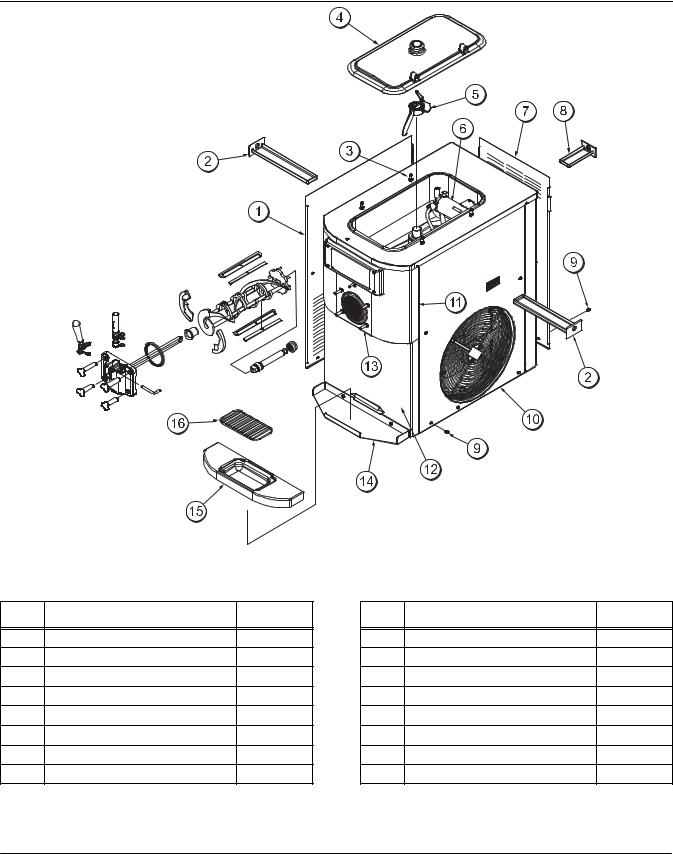
Section 4 Operator Parts Identification
Model C708
Figure 1
ITEM |
DESCRIPTION |
PART NO. |
1 |
PANEL-SIDE-LEFT |
056963 |
2 |
PAN-DRIP 11-5/8 LONG |
027503 |
3 |
PIN-RETAINING-HOPPER CVR |
043934 |
4 |
COVER-HOPPER *BLACK |
053809-1 |
5 |
BLADE A.-AGITATOR |
X56591 |
6 |
PUMP A.-MIX SIMPLIFIED S.S. |
X57029-14 |
7 |
PANEL-REAR |
056077 |
8 |
PAN A.-DRIP 5 1/2” LONG |
X56074 |
ITEM |
DESCRIPTION |
PART NO. |
9 |
SCREW-1/4-20X3/8 RHM-STNLS |
011694 |
10 |
PANEL A-SIDE-RIGHT |
X57871 |
11 |
PANEL A.-FRONT-UPPER |
X59423 |
12 |
PANEL A.-FRONT-LOWER |
X58955 |
13 |
STUD-NOSE CONE |
055987 |
14 |
SHELF-TRAY-DRIP |
056076 |
15 |
TRAY-DRIP |
056858 |
16 |
SHIELD-SPLASH |
049203 |
Operator Parts Identification |
4 |
Models C708 & C716 |
|
|
|

Models C708 & C716 |
5 |
Operator Parts Identification |
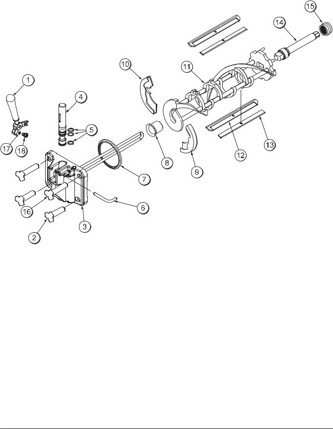
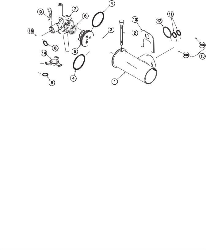
Model C708 Single Spout Door and Beater Assembly
Figure 3
ITEM |
DESCRIPTION |
PART NO. |
|
|
|
1 |
HANDLE A.-DRAW-WELDED |
X56246 |
|
|
|
2 |
NUT-STUD-BLACK 2.563“ |
058764 |
|
|
|
3 |
DOOR A.-W/BAFFLE |
X57332-SER |
|
|
|
4 |
VALVE A.-DRAW |
X55820 |
|
|
|
5 |
O-RING-DRAW VALVE-S.S. |
014402 |
|
|
|
6 |
PIN-HANDLE-SS |
055819 |
|
|
|
7 |
GASKET-DOOR HT 4”-DBL |
048926 |
|
|
|
8 |
BEARING-FRONT-SHOE |
050348 |
|
|
|
9 |
SHOE-FRONT HELIX *REAR* |
050346 |
|
|
|
ITEM |
DESCRIPTION |
PART NO. |
|
|
|
10 |
SHOE-FRONT HELIX *FRONT* |
050347 |
|
|
|
11 |
BEATER A.-3.4QT-1 PIN |
X46231 |
|
|
|
12 |
BLADE-SCRAPER-PLASTIC |
046235 |
|
|
|
13 |
CLIP-SCRAPER BLADE 7.00 |
046236 |
|
|
|
14 |
SHAFT-BEATER |
056078 |
|
|
|
15 |
SEAL-DRIVE SHAFT |
032560 |
|
|
|
16 |
NUT-STUD-BLACK 3.250” |
058765 |
|
|
|
17 |
O-RING-1/4 OD X .070W 50 |
015872 |
|
|
|
18 |
SCREW-ADJUSTMT-5/16-24 |
056332 |
|
|
|
Operator Parts Identification |
6 |
Models C708 & C716 |
|
|
|
Model C716 Door and Beater Assembly
Figure 4
ITEM |
DESCRIPTION |
PART NO. |
|
|
|
1 |
HANDLE A.-DRAW-WELDED |
X56421-1 |
|
|
|
2 |
NUT-STUD-BLACK 3.250 LONG |
058765 |
|
|
|
3 |
NUT-STUD*BLACK 2.563 LONG |
058764 |
|
|
|
4 |
DOOR A.-3SPT*HT*LG BAF |
X59923-SER |
|
|
|
5 |
PIN-HANDLE-TWIN |
059894 |
|
|
|
6 |
GASKET-DOOR HT 4”-DOUBLE |
048926 |
|
|
|
7 |
O-RING--7/8 OD X .103W |
014402 |
|
|
|
8 |
VALVE A.-DRAW |
X59888 |
|
|
|
9 |
VALVE A.-DRAW*CENTER |
X59890 |
|
|
|
10 |
SHOE-FRONT HELIX *FRONT* |
050347 |
|
|
|
ITEM |
DESCRIPTION |
PART NO. |
|
|
|
11 |
BEARING-FRONT-SHOE |
050348 |
|
|
|
12 |
SHOE-FRONT HELIX *REAR* |
050346 |
|
|
|
13 |
BLADE-SCRAPER-PLAS 8-1/8L |
046235 |
|
|
|
14 |
CLIP-SCRAPER BLADE 7.00” |
046236 |
|
|
|
15 |
BEATER A.-3.4QT-1 PIN |
X46231 |
|
|
|
16 |
SHAFT-BEATER |
032564 |
|
|
|
17 |
SEAL-DRIVE SHAFT |
032560 |
|
|
|
18 |
O-RING-1/4 OD X .070W 50 |
015872 |
|
|
|
19 |
SCREW-ADJUSTMENT-5/16-24 |
056332 |
|
|
|
Models C708 & C716 |
7 |
Operator Parts Identification |
|
|
|
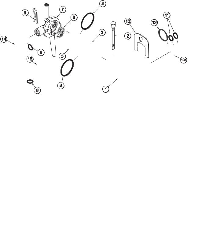
X57029-XX Pump A. - Mix Simplified (Model C708)
Operator Parts Identification |
8 |
Models C708 & C716 |
|
|
|
X57029-XX Pump A. - Mix Simplified (Model C716)
Models C708 & C716 |
9 |
Operator Parts Identification |
|
|
|
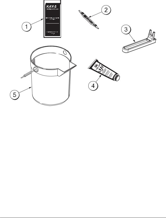
Accessories
Figure 7
ITEM |
DESCRIPTION |
PART NO. |
|
|
|
1 |
SANITIZER-KAY 5 CASE 125 |
041082 |
|
|
|
2 |
TOOL-O-RING REMOVAL |
048260-WHT |
|
|
|
3 |
TOOL-SHAFT-DRIVE-PUMP- |
0457167 |
|
HOPPER |
|
4 |
LUBRICANT-TAYLOR HI-PERF |
048232 |
|
|
|
ITEM |
DESCRIPTION |
PART NO. |
|
|
|
5 |
PAIL-MIX 10 QT. |
013163 |
|
|
|
* |
KIT A.-TUNE-UP (C708) |
X56085 |
|
|
|
* |
KIT A.-TUNE-UP (C716) |
X49463-82 |
|
|
|
* |
KIT A.-PARTS TRAY (C708) |
X57797 |
|
|
|
* |
KIT A.-PARTS TRAY (C716) |
X58449 |
|
|
|
*NOT SHOWN
Operator Parts Identification |
10 |
Models C708 & C716 |
|
|
|
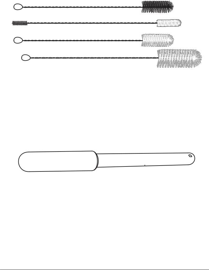
Brush Kit Assembly X44127
Models C708 & C716 |
11 |
Operator Parts Identification |
|
|
|
Section 5 |
Important: To the Operator |
||||||||
|
|
|
|
|
|
|
|
|
|
C708 |
C716 |
||||||||
|
|
|
|
|
|
|
|
|
|
|
|
|
|
|
|
|
|
|
|
|
|
|
|
|
|
|
|
|
|
|
|
|
|
|
|
|
|
|
|
|
|
|
|
|
|
|
|
|
|
|
|
|
|
|
|
|
|
|
|
|
|
|
|
|
|
|
|
|
|
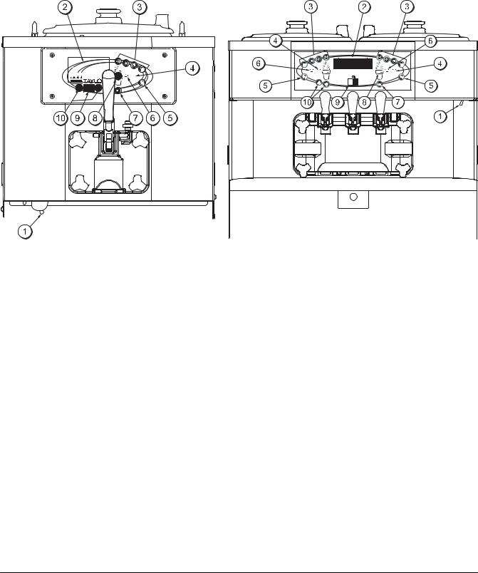
Figure 9
ITEM |
DESCRIPTION |
|
|
1 |
POWER SWITCH |
2 |
LIQUID CRYSTAL DISPLAY |
3 |
KEYPADS |
4 |
MIX OUT INDICATOR |
5 |
STANDBY INDICATOR |
6 |
MIX LOW INDICATOR |
7 |
SELECT KEY |
8 |
SERVICE MENU KEY |
9 |
BRUSH CLEAN COUNTER |
10 |
ARROW KEY(S) |
Important: To the Operator |
12 |
Models C708 & C716 |
|
|
|
Symbol Definitions
To better communicate in the International arena, symbols have replaced words on many of our operator switches, function, and fault indicators. Your Taylor equipment is designed with these International symbols.
The following chart identifies the symbol definitions.
= SELECT
= UP ARROW
= DOWN ARROW
=AUTO
=HEAT CYCLE
=WASH
 = MIX LOW
 = MIX OUT
= MENU DISPLAY
 = MIX PUMP
= STANDBY
Power Switch
When placed in the ON position, the power switch allows control panel operation.
Fluorescent Display
The fluorescent display is located on the front control panel. During normal operation the display is blank. The display is used to show menu options and notifies the operator if a fault is detected. On International models, the display will indicate the temperature of the mix in the hopper.
Indicator Lights
MIX LOW - When the MIX LOW symbol  is
is
050628
Models C708 & C716 |
13 |
Important: To the Operator |
|
|
|
If the beater motor is turning properly, touch the WASH symbol  to cancel the cycle. Touch the
AUTO symbol  to resume normal operation. If the freezer shuts down again, contact your authorized service technician.
Air/Mix Pump Reset Mechanism
This reset button protects the pump from an overload condition. Should an overload occur, the reset mechanism will trip. To reset the pump, press the reset button firmly.
 WARNING: Do not use metal objects to press the reset button. Failure to comply may result in severe personal injury or death.
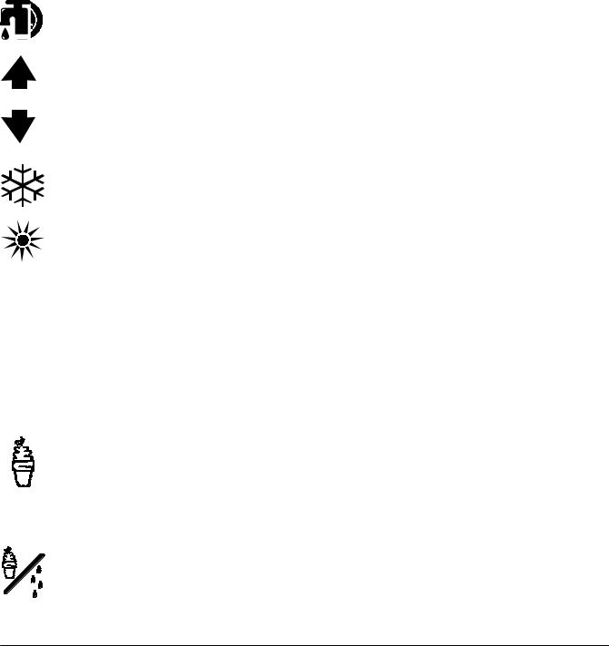
Adjustable Draw Handle
These units feature an adjustable draw handle(s) to provide the best portion control, giving a better, consistent quality to your product and controlling costs. The draw handle(s) should be adjusted to provide a flow rate of 5 to 7-1/2 oz. (142 to 213 g.) of product by weight per 10 seconds. To INCREASE the flow rate, turn the screw CLOCKWISE. To DECREASE the flow rate, turn the screw COUNTERCLOCKWISE . (See Figure 10.)
10354
+
 -
-
Figure 10
050628
Operating Screen Descriptions
The fluorescent display located in the center of the control panel is normally blank during the daily operation of the machine. The display is activated when the SEL symbol or the Manager’s Menu is selected. The display screen will also alert the operator of specific faults detected by the control.
Note: The displays illustrated in this section are those seen on the Models C708/C709. The Model C716/C717 versions may vary slightly.
Power Up Memory (Initializing)
The seven segment display should display “00” during the initializing sequence.
When the machine is powered, the control system will initialize to perform a system check. The screen will display “INITIALIZING”. There will be four types of data the system will check: LANGUAGE, SYSTEM DATA, CONFIG DATA, and LOCKOUT DATA.
Language Initialization
The UVC platform supports multiple languages by keeping specific strings in battery backed RAM. After power-up or a CPU reset, the strings are tested to see if the language strings are present and not corrupted. If the strings are present and not corrupted, initialization continues. Otherwise, the operator is prompted to select a language. While language strings are being checked for integrity, the following screen is displayed.
Initializing
Language
Note: If there is a language initialization fault, the machine will force a language selection prior to the initializing sequence. The standard menu LED’s should light, as if it were in a menu. If a language has been selected, the unit is powered down, the machine should not ask for a language unless there is another language initialization fault. English is the factory default setting.
Important: To the Operator |
14 |
Models C708 & C716 |
|
|
|

System Data
System data is protected separately from the rest of the data in memory. System data includes variables that change frequently such as the mode the machine is in, lockout status, serving counters, fault codes, and others. While System Data is being checked the following screen is displayed.
Initializing
System Data
If the System Data is corrupted, the machine is set to OFF, the serving counters are set to zero, and the faults are cleared. A “SYSTEM CRC ERR” fault is set and displayed on the VFD. An acknowledgement (SEL key) is required.
Configuration Data
Configuration data is separate from the rest of the data in the memory. Configuration data is information entered through operator and service menus. While Configuration Data is being checked the following screen is displayed.
Initializing
Config Data
If Configuration data is corrupted, all user and service settings are set to defaults. A “CONFIG CRC ERR” fault is set and displayed on the VFD. The system will continue to operate in its previous mode but according to default settings.
Lockout Data
Lockout data is protected separately from the rest of the data in the memory. While the Lockout Data is being checked, the following screen is displayed.
Initializing
Lockout Data
If Lockout Data is corrupted, all lockout history data is cleared. A “LOCKOUT CRC ERR” fault is displayed.
After the memory integrity has been tested, the Safety Timeout screen will be displayed.
Heat Cycle Data
Heat cycle data is checked separately from the rest of the data in memory. Each individual Heat Cycle Data record is monitored for corruption individually. At the start of a heat cycle, the next Heat Cycle data record is cleared and data for the heat cycle is written to it. The current Heat Cycle Data is displayed as the first heat cycle record in the HEAT CYCLE DATA menu option.
The heat cycle data records are checked for integrity when the record is accessed, presently only through the HEAT CYCLE DATA menu option. (For additional Heat Cycle Data information,
see page 24.)
Once the system has initialized, the number of days until brush cleaning is required is indicated on the control panel. The SAFETY TIMEOUT screen will be displayed with the alarm on for 60 seconds or until any control symbol is touched.
SAFETY TIMEOUT
ANY KEY ABORTS
Power Switch OFF
After the safety timeout has been completed and the power switch is OFF, the following screen is displayed.
POWER SWITCH OFF - = - = - = - = - = - UNIT CLEANED
050628
Models C708 & C716 |
15 |
Important: To the Operator |
|
|
|

Power Switch ON
When the power switch is placed in the ON position, the control panel touch keys become operative. The fluorescent display will be either blank or indicate that the unit has been cleaned.
UNIT CLEANED
International Models Only:
Some International models will continuously display the temperature of the mix hopper when the power switch is in the ON position.
HOPPER 21.0
UNIT CLEANED
If the control is set for international configuration, the following screen will appear when the heat symbol is touched.
ARE YOU SURE
>Yes No
Use the up or down arrow symbol to move the cursor to “YES”. Touch the SEL symbol to immediately start a heat cycle.
Note: The machine must be in AUTO or STANDBY and have sufficient mix in the hopper before the machine can successfully enter the HEAT mode of operation.
050628
Heat Cycle
The HEAT symbol on the control panel is illuminated throughout the heat treatment cycle. Two warning messages will be displayed on the screen. “DO NOT DRAW” will be displayed when the mix temperature is below 130°F (54.4°C).
DO NOT DRAW
When the temperature of the mix is above 130°F (54.4°C) the screen will display a message indicating that HOT PRODUCT is in the machine.
HOT PRODUCT
 DO NOT attempt to draw product or disassemble the unit during the HEAT cycle. The product is hot and under extreme pressure.
In the HEAT cycle, the mix temperature in the hopper and freezing cylinder must be raised to 151°F (66.1°C) within 90 minutes.
When the heating phase is complete, the freezer goes into the holding phase of the cycle. The holding phase will keep the temperature above 151°F (66.1°C) for a minimum of 35 minutes.
The final phase of the heat treatment cycle is the cooling phase. The freezer must cool the mix below 41°F (5°C) within 90 minutes.
When the entire heat cycle has been completed, the HEAT symbol will no longer be illuminated. The machine will enter the STANDBY mode (STANDBY symbol illuminates). The machine can be placed in AUTO or left in STANDBY.
To comply with health codes, heat treatment system freezers must complete a heat treatment cycle daily, and must be disassembled and brush cleaned a minimum of every 14 days. Brush cleaning is the normal disassembly and cleaning procedure found in the Operator Manual. Failure to follow these guidelines will cause the control to lock the freezer out of the AUTO mode.
Important: To the Operator |
16 |
Models C708 & C716 |
|
|
|
If the Heat Treatment Cycle fails, the screen will display a failure message and return the freezer to the STANDBY mode.
Always comply with local guidelines for the maximum number of days allowed between brush clean cycles. (See the Manager’s Menu for setting the Brush Clean interval.)
Freezer Locks
There are two types of freezer lock conditions that can occur: Hard Lock or Soft Lock. A Hard Lock requires the machine be disassembled and brush cleaned. A Soft Lock can be corrected by either disassembling and brush cleaning the machine, or by starting another heat treatment cycle.
Hardlock
There are two causes of a hard lock failure. The freezer will hardlock if either the Brush Clean Timer has elapsed or if a Thermistor Failure (Freezing Cylinder or Hopper) occurred during a Heat cycle.
1.The following screen will be displayed if a Brush Clean Cycle Time has occurred.
BRUSH CLEAN TIMEOUT
FREEZER LOCKED
CLEANING REQ’D
>BRUSH CLEAN
Touching the SEL symbol will display the following screen.
FREEZER LOCKED
2.The following screen will display if there has been a thermistor failure (freezing cylinder or hopper) during the heat treatment process.
SYSTEM FAULT
FREEZER LOCKED
SERVICE REQ’D
>BRUSH CLEAN
Touching the SEL symbol will indicate which thermistor caused the Hard Lock.
HOPPER THERM BAD
FREEZER LOCKED
If the machine has hard locked and an attempt is made to enter AUTO, the machine will enter the STANDBY mode and display the following message.
FREEZER LOCKED
To restore the message that identified the reason for the hard lock, turn the power switch OFF for five seconds and then return the power switch to the ON position. The original message with the reason for the Hard Lock will be displayed.
The FREEZER LOCKED message will remain on the display until the brush clean requirements are fulfilled. The freezer must be disassembled in order to activate the five minute timer on the display screen. Once the timer counts down to zero, the lockout is cleared.
Soft Lock
If a heat treatment cycle has not been initiated within the last 24 hours, a soft lock failure will occur. A soft lock allows the operator to correct the cause of the soft lock. The operator has the option of either starting another heat cycle or brush cleaning the machine. When a soft lock occurs, the machine will go into the STANDBY mode. The following message is displayed on the screen. The reason for the soft lock is indicated on the second line.
NO HEAT CYCLE START
REASON
>HEAT CYCLE BRUSH CLEAN
If the reason for the soft lock has been corrected, selecting HEAT CYCLE initiates a Heat Cycle immediately. Selecting BRUSH CLEAN when the previous message is displayed will hard lock the machine and brush cleaning will be necessary.
050628
Models C708 & C716 |
17 |
Important: To the Operator |
|
|
|

Following are the variable messages for soft lock failures that appear on the second line of the screen.
POWER SWITCH OFF |
Power switch was in the |
|
OFF position. |
|
|
MIX OUT PRESENT |
There was a mix out |
|
condition present. |
AUTO OR STANDBY |
The machine was not in |
OFF |
the AUTO or STANDBY |
|
mode. |
NO HEAT CYCLE |
A heat treatment cycle |
TRIED |
was not attempted in |
|
the last 24 hours. |
|
(AUTO HEAT TIME |
|
was advanced or a pow- |
|
er loss was experienced |
|
at the time the cycle |
|
was to occur.) |
If the following screen appears, a soft lock has occurred during the heat treatment cycle.
HEAT TREAT FAILURE
FREEZER LOCKED
>HEAT CYCLE BRUSH CLEAN
A soft lock can also occur any time during operation when the hopper or freezing cylinder temperature rises above 59°F (15°C), the temperature rises and remains above 45°F(7°C) for more than one hour, or the temperature rises and remains above 41°F(5°C) for more than four hours.
If a PRODUCT OVER TEMPERATURE condition occurs during operation, the following screen will appear.
PRODUCT OVER TEMP
>HEAT CYCLE BRUSH CLEAN
When one of these messages appears, automatic freezer operation cannot take place until the freezer is disassembled and brush cleaned, or has completed a heat treatment cycle.
Once the freezer is unlocked by starting a heat treatment cycle the HEAT symbol will illuminate and the following message will be displayed on the screen.
DO NOT DRAW
If BRUSH CLEAN is selected to clear the lockout by brush cleaning the machine, the FREEZER LOCKED message will remain on the display until the brush clean requirements are fulfilled. The freezer must be disassembled in order to activate the five minute timer on the display screen. Once the timer counts down to zero, the lockout is cleared.
FREEZER LOCKED
To restore the message that identified the reason for the soft lock, turn the power switch OFF for five seconds, and then return the power switch to the ON position. The original message with the reason for the soft lock will be displayed.
050628
Important: To the Operator |
18 |
Models C708 & C716 |
|
|
|
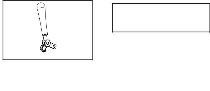
Manager’s Menu
The Manager’s Menu is used to enter the operator function displays. To access the Menu, touch the center of the CONE symbol on the control panel. The arrow symbols, the SEL symbol and the CONE symbol will be lit when the ACCESS CODE screen is displayed.
13201 |
® |
SEL |
Figure 11
In the Menu program, the arrow symbols and the SEL symbol will function as menu keys.
UP ARROW - increases the value above the cursor and is used to scroll upward in text displays.
DOWN ARROW - decreases the value above the cursor and is used to scroll downward in text displays.
SEL - advances the cursor position to the right and is used to select menu options.
There is a two minute time-out in effect during the Manager’s Menu. While in the Manager’s Menu, if no activity occurs within a two minute period, the display will exit to the Main Menu. There is one exception to this time-out, and that is the Current Conditions Display.
Note: The machine will continue operation in the mode it was in when the Menu was selected. However, the control keys will not be lit and are non-functional when the Manager’s Menu is displayed. The control keys are functional in the Manager’s Menu when the CURRENT CONDITIONS screen is displayed. (See CURRENT CONDITIONS on page 25.)
Entering Access Code
With the ACCESS CODE screen on the display, use the SEL symbol to set the first code number in the cursor position. When the correct number is selected, touch the SEL symbol to move the cursor to the next number position.
ENTER ACCESS CODE
8 |
3 |
0 |
9 |
__ |
|
|
|
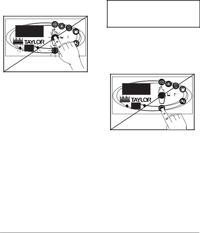
Continue to enter the proper access code numbers (8309) until all four numbers are displayed, then touch the SEL symbol. The Manager’s Menu list will display on the screen, provided the correct access code is entered.
If an incorrect number is entered for the access code, the display will exit the Menu program when the SEL symbol is touched.
13202
®
SEL
Figure 12
Manager Menu Options
Touch the ARROW symbols to move up or down through the Menu. Select a Menu option by touching the SEL symbol. Exit the Menu program by selecting EXIT FROM MENU or touch the CONE symbol.
The following menu options are listed in the Manager’s Menu.
EXIT FROM MENU
RESET DRAW COUNTER
SET CLOCK
AUTO HEAT TIME
050628
Models C708 & C716 |
19 |
Important: To the Operator |
|
|
|
 Loading...