


Model C903
Slush Freezer
Operating Instructions
057072-M
6/10/04

Complete this page for quick reference when service is required:
Taylor Distributor:
Address:
Phone:
Service:
Parts:
Date of Installation:
Information found on the data label:
Model Number:
Serial Number:
Electrical Specs: Voltage |
|
Cycle |
|||||
Phase |
|
|
|
|
|
||
Maximum Fuse Size: |
|
|
|
|
A |
||
Minimum Wire Ampacity: |
|
|
|
|
A |
||
E April, 2004 Taylor All rights reserved.
057072--M
The word Taylor and the Crown design
are registered trademarks in the United States of America and certain other countries.
Taylor
a division of Carrier Commercial Refrigeration, Inc. 750 N. Blackhawk Blvd.
Rockton, IL 61072

|
Table of Contents |
|
Section 1 |
To the Installer . . . . . . . . . . . . . . . . . . . . . . . . . . . . . . . . . . . . . . . . . . . . |
1 |
Air Cooled Units . . . . . . . . . . . . . . . . . . . . . . . . . . . . . . . . . . . . . . . . . . . . . . . . . . . . . . . |
1 |
|
Water Connections . . . . . . . . . . . . . . . . . . . . . . . . . . . . . . . . . . . . . . . . . . . . . . . . . . . . |
1 |
|
Electrical Connections . . . . . . . . . . . . . . . . . . . . . . . . . . . . . . . . . . . . . . . . . . . . . . . . . |
1 |
|
Section 2 |
To the Operator . . . . . . . . . . . . . . . . . . . . . . . . . . . . . . . . . . . . . . . . . . . |
2 |
Compressor Warranty Disclaimer . . . . . . . . . . . . . . . . . . . . . . . . . . . . . . . . . . . . . . . |
2 |
|
Section 3 |
Safety . . . . . . . . . . . . . . . . . . . . . . . . . . . . . . . . . . . . . . . . . . . . . . . . . . . . |
3 |
Section 4 |
Operator Parts Identification . . . . . . . . . . . . . . . . . . . . . . . . . . . . . . . |
4 |
Beater Bowl Assembly . . . . . . . . . . . . . . . . . . . . . . . . . . . . . . . . . . . . . . . . . . . . . . . . . |
5 |
|
Mix Cabinet Assembly - Standard . . . . . . . . . . . . . . . . . . . . . . . . . . . . . . . . . . . . . . . |
6 |
|
Mix Cabinet Assembly - KanPak . . . . . . . . . . . . . . . . . . . . . . . . . . . . . . . . . . . . . . . . |
7 |
|
Mix Cabinet Assembly - Optional . . . . . . . . . . . . . . . . . . . . . . . . . . . . . . . . . . . . . . . . |
8 |
|
Peristaltic Pump Tube Replacement . . . . . . . . . . . . . . . . . . . . . . . . . . . . . . . . . . . . . |
9 |
|
Accessories |
. . . . . . . . . . . . . . . . . . . . . . . . . . . . . . . . . . . . . . . . . . . . . . . . . . . . . . . . . . |
10 |
Section 5 |
Important: To the Operator . . . . . . . . . . . . . . . . . . . . . . . . . . . . . . . . . |
11 |
Power Switch . . . . . . . . . . . . . . . . . . . . . . . . . . . . . . . . . . . . . . . . . . . . . . . . . . . . . . . . . |
11 |
|
Viscosity Adjustment . . . . . . . . . . . . . . . . . . . . . . . . . . . . . . . . . . . . . . . . . . . . . . . . . . . |
11 |
|
Display . . . |
. . . . . . . . . . . . . . . . . . . . . . . . . . . . . . . . . . . . . . . . . . . . . . . . . . . . . . . . . . . |
12 |
Keypad . . . |
. . . . . . . . . . . . . . . . . . . . . . . . . . . . . . . . . . . . . . . . . . . . . . . . . . . . . . . . . . . |
12 |
Flavor Lights . . . . . . . . . . . . . . . . . . . . . . . . . . . . . . . . . . . . . . . . . . . . . . . . . . . . . . . . . |
12 |
|
Audio Alarm . . . . . . . . . . . . . . . . . . . . . . . . . . . . . . . . . . . . . . . . . . . . . . . . . . . . . . . . . . |
12 |
|
Passcodes |
. . . . . . . . . . . . . . . . . . . . . . . . . . . . . . . . . . . . . . . . . . . . . . . . . . . . . . . . . . . |
12 |
Power Up Initialization Screens . . . . . . . . . . . . . . . . . . . . . . . . . . . . . . . . . . . . . . . . . |
12 |
|
Operator Menus . . . . . . . . . . . . . . . . . . . . . . . . . . . . . . . . . . . . . . . . . . . . . . . . . . . . . . |
13 |
|
Bowl Modes . . . . . . . . . . . . . . . . . . . . . . . . . . . . . . . . . . . . . . . . . . . . . . . . . . . . . . . . . . |
29 |
|
Cleaning Lockout . . . . . . . . . . . . . . . . . . . . . . . . . . . . . . . . . . . . . . . . . . . . . . . . . . . . . |
31 |
|
Section 6 |
Operating Procedures . . . . . . . . . . . . . . . . . . . . . . . . . . . . . . . . . . . . . |
34 |
Assembly . |
. . . . . . . . . . . . . . . . . . . . . . . . . . . . . . . . . . . . . . . . . . . . . . . . . . . . . . . . . . . |
34 |
Sanitizing . |
. . . . . . . . . . . . . . . . . . . . . . . . . . . . . . . . . . . . . . . . . . . . . . . . . . . . . . . . . . . |
36 |
Installing the Mix Tanks (Non Bag-In-Box Product Only) . . . . . . . . . . . . . . . . . . . . |
39 |
|
Installing the Syrup Bag-in-Box (B.I.B. Product Only) . . . . . . . . . . . . . . . . . . . . . . |
40 |
|
Ratio Products (Products Requiring Water Added) . . . . . . . . . . . . . . . . . . . . . . . . . |
42 |
|
Priming . . . |
. . . . . . . . . . . . . . . . . . . . . . . . . . . . . . . . . . . . . . . . . . . . . . . . . . . . . . . . . . . |
43 |
Table of Contents |
Model C903 |
|
|

Table of Contents - Page 2
Cleaning Procedure . . . . . . . . . . . . . . . . . . . . . . . . . . . . . . . . . . . . . . . . . . . . . . . . . . . 43
Rinsing . . . . . . . . . . . . . . . . . . . . . . . . . . . . . . . . . . . . . . . . . . . . . . . . . . . . . . . . . . . . . . 43
Disassembly . . . . . . . . . . . . . . . . . . . . . . . . . . . . . . . . . . . . . . . . . . . . . . . . . . . . . . . . . . 46
Brush Cleaning . . . . . . . . . . . . . . . . . . . . . . . . . . . . . . . . . . . . . . . . . . . . . . . . . . . . . . . 47
Daily Opening and Closing Procedures . . . . . . . . . . . . . . . . . . . . . . . . . . . . . . . . . . 49
Section 7 Important: Operator Checklist . . . . . . . . . . . . . . . . . . . . . . . . . . . . . . 50
During Cleaning and Sanitizing . . . . . . . . . . . . . . . . . . . . . . . . . . . . . . . . . . . . . . . . . 50
Troubleshooting Bacterial Count: . . . . . . . . . . . . . . . . . . . . . . . . . . . . . . . . . . . . . . . . 50
Regular Maintenance Checks: . . . . . . . . . . . . . . . . . . . . . . . . . . . . . . . . . . . . . . . . . . 50
Shipping / Winter Storage . . . . . . . . . . . . . . . . . . . . . . . . . . . . . . . . . . . . . . . . . . . . . . 50
Section 8 Troubleshooting Guide . . . . . . . . . . . . . . . . . . . . . . . . . . . . . . . . . . . . 51
Section 9 Parts Replacement Schedule . . . . . . . . . . . . . . . . . . . . . . . . . . . . . . . 52
Section 10 Parts List . . . . . . . . . . . . . . . . . . . . . . . . . . . . . . . . . . . . . . . . . . . . . . . . . 53
Wiring Diagrams . . . . . . . . . . . . . . . . . . . . . . . . . . . . . . . . . . . . . . . . . . . . . . . . . . . . . . 64
Note: Continuing research results in steady improvements; therefore, information in this manual is subject to change without notice.
Model C903 |
Table of Contents |
|
|
Section 1 |
To the Installer |
|
|
This machine is designed for indoor use only.
 DO NOT install the machine in an area where a water jet could be used. Failure to follow this instruction may result in serious electrical shock.
Air Cooled Units
Air cooled units require a minimum air clearance of 3” (76 mm) in the back and 12” (305 mm) on the top. This is required to allow for adequate air flow across the condensers. Failure to allow adequate clearance can reduce the refrigeration capacity of the freezer and possibly cause permanent damage to the compressor.
Water Connections
An adequate cold water supply must be provided with a hand shut-off valve. On the back of the unit, a 1/4” male flare water connection has been provided for easy hook-up. A flexible line is recommended, if local codes permit. A minimum of 25 psi water pressure is required to avoid a low water pressure alarm. A booster pump must be provided if this pressure is not available. It is always a good practice to have a filter system to improve the quality of the water and to avoid clogging the operating components.
Note: Water lines beyond 200 ft. (61 m) require 1/2” (13 mm) water lines.
INSTALL POTABLE WATER CONNECTION WITH ADEQUATE BACK-FLOW PROTECTION TO COMPLY WITH APPLICABLE NATIONAL, STATE AND LOCAL CODES.
Electrical Connections
 CAUTION: THIS EQUIPMENT MUST BE PROPERLY GROUNDED. FAILURE TO DO SO CAN RESULT IN SEVERE PERSONAL INJURY FROM ELECTRICAL SHOCK.
This unit must be plugged into a properly grounded receptacle. A dedicated circuit is recommended, sized for 15A usage. The standard voltage specification is 115V-60-1, however other electrical specifications may be available. Follow the specifications listed on your data label.
In the United States, this equipment is intended to be installed in accordance with the National Electrical Code (NEC), ANSI/NFPA 70-1987. The purpose of the NEC code is the practical safeguarding of persons and property from hazards arising from the use of electricity. This code contains provisions considered necessary for safety. Compliance therewith and proper maintenance will result in an installation essentially free from hazard!
In all other areas of the world, equipment should be installed in accordance with the existing local codes. Please contact your local authorities.
Stationary appliances which are not equipped with a power cord and a plug or other device to disconnect the appliance from the power source must have an all-pole disconnecting device with a contact gap of at least 3 mm installed in the external installation.
FOLLOW YOUR LOCAL ELECTRICAL CODES!
050902
Model C903 |
1 |
To the Installer |
|
|
|

Section 2 |
To the Operator |
|
|
The freezer you have purchased has been carefully engineered and manufactured to give you dependable operation. The Taylor Model C903, when properly operated and cared for, will produce a consistent quality product. Like all mechanical products, they will require cleaning and maintenance. A minimum amount of care and attention is necessary if the operating procedures outlined in this manual are followed closely.
This Operator’s Manual should be read before operating or performing any maintenance on your equipment.
Your Taylor freezer will NOT eventually compensate for and correct any errors during the set-up or filling operations. Thus, the initial assembly and priming procedures are of extreme importance. It is strongly recommended that personnel responsible for the equipment’s operation, both assembly and disassembly, sit down together and go through these procedures in order to be properly trained and to make sure that no misunderstandings exist.
In the event you should require technical assistance, please contact your local authorized Taylor Distributor.
Note: Constant research results in steady improvements; therefore, information in this manual is subject to change without notice.
 If the crossed out wheeled bin symbol is affixed to this product, it signifies that this product is compliant with the EU Directive as well as other similar legislation in effect after August 13, 2005. Therefore, it must be collected separately after its use is completed, and cannot be disposed as unsorted municipal waste.
The user is responsible for returning the product to the appropriate collection facility, as specified by your local code.
For additional information regarding applicable local laws, please contact the municipal facility and/or local distributor.
Compressor Warranty Disclaimer
The refrigeration compressor(s) on this machine are warranted for the term indicated on the warranty card accompanying this machine. However, due to the Montreal Protocol and the U.S. Clean Air Act Amendments of 1990, many new refrigerants are being tested and developed, thus seeking their way into the service industry. Some of these new refrigerants are being advertised as drop-in replacements for numerous applications. It should be noted that, in the event of ordinary service to this machine’s refrigeration system, only the refrigerant specified on the affixed data label should be used. The unauthorized use of alternate refrigerants will void your compressor warranty. It will be the owner’s responsibility to make this fact known to any technician he employs.
It should also be noted that Taylor does not warrant the refrigerant used in its equipment. For example, if the refrigerant is lost during the course of ordinary service to this machine, Taylor has no obligation to either supply or provide its replacement either at billable or unbillable terms. Taylor does have the obligation to recommend a suitable replacement if the original refrigerant is banned, obsoleted, or no longer available during the five year warranty of the compressor.
Taylor will continue to monitor the industry and test new alternates as they are being developed. Should a new alternate prove, through our testing, that it would be accepted as a drop-in replacement, then the above disclaimer would become null and void. To find out the current status of an alternate refrigerant as it relates to your compressor warranty, call the local Taylor Distributor or the Taylor Factory. Be prepared to provide the Model/Serial Number of the unit in question.
070124
To the Operator |
2 |
Model C903 |
|
|
|
Section 3 |
Safety |
We at Taylor are concerned about the safety of the operator when he or she comes in contact with the freezer and its parts. Taylor has gone to extreme efforts to design and manufacture built-in safety features to protect both you and the service technician. As an example, warning labels have been attached to the freezer to further point out safety precautions to the operator.
 IMPORTANT - Failure to adhere to the following safety precautions may result in severe personal injury. Failure to comply with these warnings may damage the machine and its components. Component damage will result in part replacement expense and service repair expense.
To Operate Safely:
 DO NOT operate the freezer without reading this operator’s manual. Failure to follow this instruction may result in equipment damage, poor freezer performance, health hazards, or personal injury.
SDO NOT operate the freezer unless it is properly grounded.
SDO NOT operate the freezer with larger fuses than specified on the freezer data label.
SDO NOT attempt any repairs unless the main power supply to the freezer has been disconnected.
Failure to follow these instructions may result in electrocution or damage to the machine. Consult your electrician.
 DO NOT use a water jet to clean or rinse the freezer. Failure to follow this instruction may result in serious electrical shock.

 This freezer must be placed on a level surface. Failure to comply may result in personal injury or equipment damage.
SDO NOT allow untrained personnel to operate this machine.
SDO NOT operate the freezer unless all service panels and access doors are restrained with screws.
Failure to follow these instructions may result in contaminated product or personal injury from hazardous moving parts.
SDO NOT put objects or fingers in the bowl spout.
SUSE EXTREME CAUTION when installing the magnetic drive beater assembly.
Failure to follow these instructions may result in contaminated product or personal injury from blade contact.
IMPORTANT: Do not obstruct the air intake and discharge openings. A minimum air clearance of 3” (76 mm) in the back and 12” (305 mm) on the top is required. Failure to follow this instruction may cause poor freezer performance and damage to the machine.
This freezer is designed to operate indoors, under normal ambient temperatures of 70°-75°F (21°-24°C). The freezer has successfully performed in high ambient temperatures of 104°F (40°C) at reduced capacities.
NOISE LEVEL: Airborne noise emission does not exceed 78 dB(A) when measured at a distance of 1.0 meter from the surface of the machine and at a height of 1.6 meters from the floor.
The following statement applies to RFID units only:
FCC ID: RPPTAYLORRFIDSYS
This device complies with Part 15 of the FCC Rules. Operation is subject to the following two conditions:
(1) This device may not cause harmful interference, and (2) this device must accept any interference received including interference that may cause undesired operation.
070124
Model C903 |
3 |
Safety |
|
|
|

Section 4 Operator Parts Identification
ITEM |
DESCRIPTION |
PART NO. |
|
|
|
*1 |
LENS-FLAVOR CARD (L & R) |
057161 |
|
|
|
*2 |
LENS-DISPLAY-FRONT |
057330 |
|
|
|
3 |
FILTER-AIR-17.00LX12.00HX.70 |
052779-8 |
|
|
|
4 |
PANEL-SIDE-LOWER LEFT |
057052 |
|
|
|
5 |
HOOD |
057050 |
|
|
|
6 |
PANEL-REAR |
057054 |
|
|
|
7 |
PANEL-SIDE-UPPER |
057049 |
|
|
|
*8 |
LENS-DISPLAY-LIGHTED-SIDE |
057160 |
|
(L & R) |
|
9 |
PANEL-SIDE-LOWER RIGHT |
057053 |
|
|
|
10 |
DOOR A.-CABINET |
X57081 |
|
|
|
11 |
GASKET-BASE PAN |
057154 |
|
|
|
040802 |
|
|
ITEM |
DESCRIPTION |
PART NO. |
|
|
|
12 |
TRAY-DRIP |
057051 |
|
|
|
13 |
DISPENSER-CUP-ADJUSTABLE |
057144 |
|
|
|
13a |
KIT-GASKET-4 DISP CUP |
057144-4 |
|
|
|
13b |
RING-TRIM-DISPENSER CUP |
057144-3 |
|
|
|
14 |
SHIELD-SPLASH |
057044 |
|
|
|
15 |
SCREW-10-24 X 1/2 TRUSS HD |
049189 |
|
|
|
16 |
BULB-FLUORESCENT U SHAPE |
057157-12 |
|
|
|
17 |
BULB-FLUORSCENT CIRCL |
054683-2 |
|
|
|
18 |
FILTER-AIR |
057135 |
|
|
|
19 |
SHELF-DRIP TRAY |
057307 |
|
|
|
*CONTACT YOUR PRODUCT SUPPLIER OR LOCAL TAYLOR DISTRIBUTOR FOR MERCHANDISING GRAPHICS.
Operator Parts Identification |
4 |
Model C903 |
|
|
|
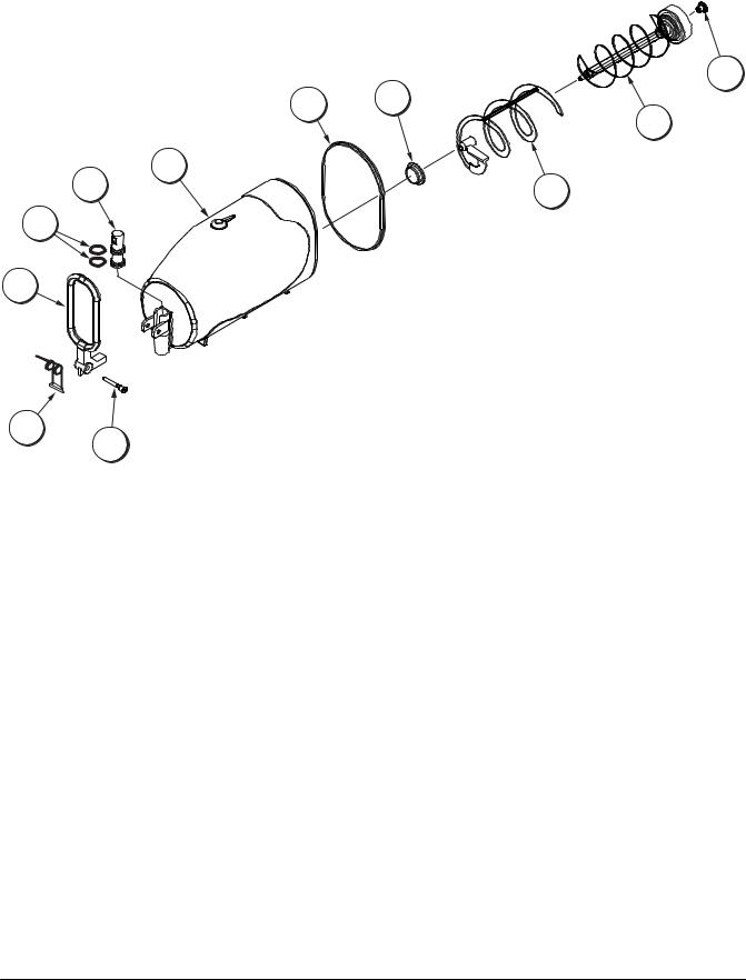
Beater Bowl Assembly
11
7 8
10
6
5 |
9 |
|
4 |
3
2
1
Figure 1
ITEM |
DESCRIPTION |
PART NO. |
|
|
|
1 |
PIN-PIVOT |
046461-1 |
|
|
|
2 |
SPRING-DRAW |
046460 |
|
|
|
3 |
HANDLE-DRAW *BLACK |
046459-1 |
|
|
|
4 |
O-RING *DRAW VALVE |
046458 |
|
|
|
5 |
VALVE-DRAW |
046457 |
|
|
|
6 |
BOWL-MIX 10 QT |
057036 |
|
|
|
ITEM |
DESCRIPTION |
PART NO. |
|
|
|
7 |
GASKET-BOWL |
057042 |
|
|
|
8 |
BEARING-FRONT |
046462 |
|
|
|
9 |
BLADE-SCRAPER-OUTER |
056754 |
|
|
|
10 |
BEATER-MAGNETIC |
052204 |
|
|
|
11 |
BEARING-REAR WALL-OUTER |
052202 |
|
|
|
Model C903 |
5 |
Operator Parts Identification |
|
|
|
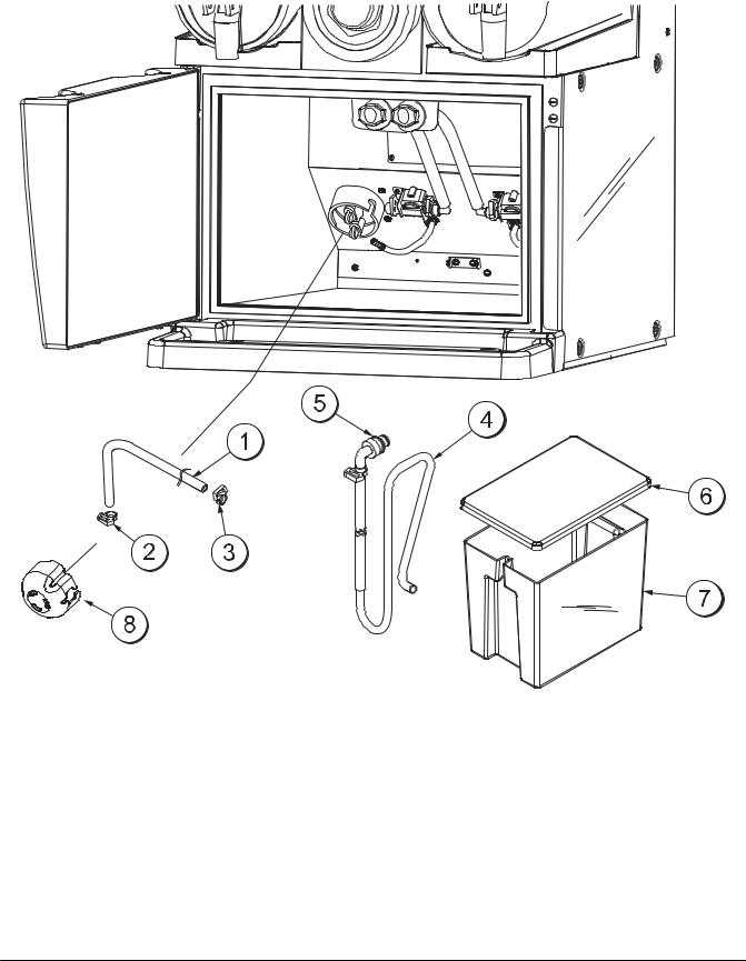
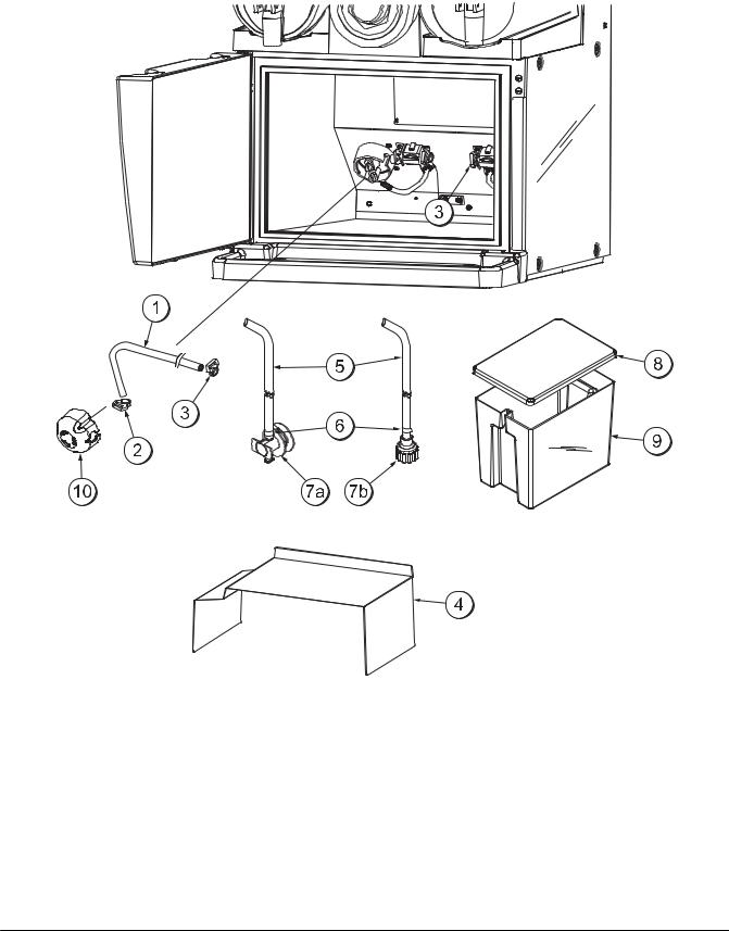
Mix Cabinet Assembly - Standard
Figure 2
ITEM |
DESCRIPTION |
PART NO. |
|
|
|
1 |
TUBE-PERISTALTIC PUMP |
057125 |
|
|
|
2 |
CLAMP-HOSE-SNAP IT 11/32 |
053630 |
|
|
|
3 |
CLAMP-HOSE-SNAP IT 17/32 |
052021 |
|
|
|
4 |
TUBE A.-PRODUCT-TANK |
X58433 |
|
(MIX TANK) |
|
ITEM |
DESCRIPTION |
PART NO. |
|
|
|
5 |
O-RING - 3/8 |
021265 |
|
|
|
6 |
COVER-MIX TANK |
057924 |
|
|
|
7 |
TANK-MIX |
057923 |
|
|
|
8 |
COVER-PUMP |
058832 |
|
|
|
Operator Parts Identification |
6 |
Model C903 |
|
|
|
Mix Cabinet Assembly - KanPak
1 |
4b |
|
|
4c |
4 |
2 |
3 |
|
|
|
|
9
4a
5
8 |
6 |
7
Figure 3
ITEM |
DESCRIPTION |
PART NO. |
|
|
|
1 |
TUBE-PERISTALTIC PUMP |
057125 |
2 |
CLAMP-HOSE-SNAP IT 11/32 |
053630 |
|
|
|
3 |
CLAMP-HOSE-SNAP IT 17/32 |
052021 |
|
|
|
4 |
TUBE A.-PRODUCT (B.I.B.) |
X58141 |
|
|
|
4a |
FITTING-BIB-QD ELBOW 3/8 |
063103 |
|
|
|
4b |
FITTING-BIB-QD MALE 3/8 |
058143 |
|
|
|
ITEM |
DESCRIPTION |
PART NO. |
|
|
|
4c |
CLAMP-HOSE-SNAP IT |
052021 |
5 |
COVER-REAR-MIX TANK |
062021-R |
|
|
|
6 |
COVER-FRONT-MIX TANK |
062021-F |
|
|
|
7 |
TANK-MIX |
057923 |
|
|
|
8 |
ANTENNA ASSEMBLY |
058291 |
|
|
|
9 |
COVER-PUMP |
058832 |
|
|
|
060712
Model C903 |
7 |
Operator Parts Identification |
|
|
|
Mix Cabinet Assembly - Optional
Figure 4
ITEM |
DESCRIPTION |
PART NO. |
|
|
|
1 |
TUBE-PERISTALTIC PUMP |
057125 |
2 |
CLAMP-HOSE-SNAP IT 11/32 |
053630 |
|
|
|
3 |
CLAMP-HOSE-SNAP IT 17/32 |
052021 |
|
|
|
4 |
SHELF-CABINET |
059188 |
|
|
|
5 |
TUBE-VINYL 3/8 ID X 9/16 OD |
020943-28 |
|
|
|
6 |
CLAMP-HOSE 9/16 STEPLESS |
053959 |
|
|
|
ITEM |
DESCRIPTION |
PART NO. |
|
|
|
7a |
FITTING-BAG *BIB PEPSI |
042945 |
7b |
FITTING-BAG *BIB COKE |
048176 |
|
|
|
8 |
COVER-MIX TANK |
057924 |
|
|
|
9 |
TANK-MIX |
057923 |
|
|
|
10 |
COVER-PUMP |
058832 |
|
|
|
Operator Parts Identification |
8 |
Model C903 |
|
|
|
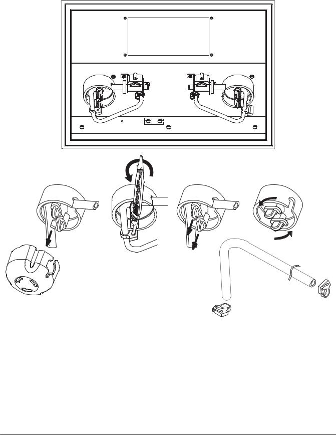
Peristaltic Pump Tube Replacement
Figure 5
Tube Replacement Procedure
1.Remove the black pump cover.
2.Twist open the hose clamps to disengage them from the hose. (Note: The o-ring tool can be used as an aid to remove the clamps.)
3.Pull the rounded tabs out all the way to disengage them from the disk and then rotate the tabs.
4.Remove the tube.
5.Replace the tube and rotate the tabs back into the locking position. Make sure the pins are securely locked in the disk.
Model C903 |
9 |
Operator Parts Identification |
|
|
|
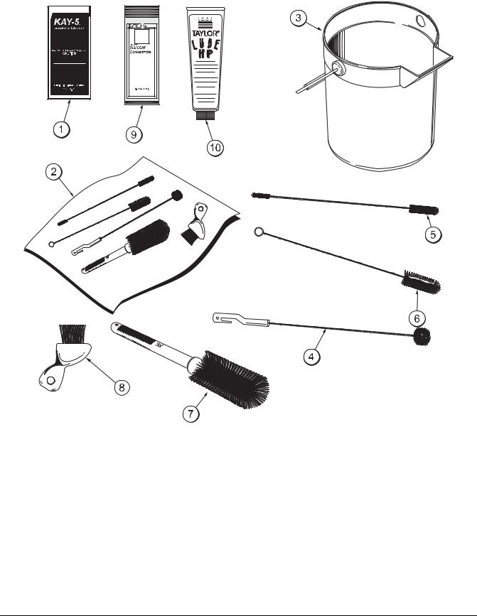
Accessories
Figure 6
ITEM |
DESCRIPTION |
PART NO. |
|
|
|
1 |
SANITIZER KAY-5 125 PKTS |
041082 |
2 |
BRUSH A.-PACKAGE |
X58793 |
|
(CONSISTS OF BRUSH ITEMS |
|
|
4 - 8) |
|
3 |
PAIL-MIX 10 QT. |
013163 |
|
|
|
4 |
BRUSH-BEATER & SHAFT |
500313 |
|
|
|
5 |
BRUSH-DOUBLE ENDED |
013072 |
|
|
|
ITEM |
DESCRIPTION |
PART NO. |
|
|
|
6 |
BRUSH-DRAW VALVE 1”ODX2” |
013073 |
7 |
BRUSH-MIX PUMP BODY-3”X7” |
023316 |
|
|
|
8 |
BRUSH-END-DOOR-SPOUT |
039719 |
|
|
|
9 |
DETERGENT-YELLOW |
059070 |
|
DISHSOAP |
|
10 |
LUBRICANT-TAYLOR HI PERF |
048232 |
|
|
|
*11 |
TUNE-UP KIT |
X49463-69 |
|
|
|
*NOT SHOWN
040813
Operator Parts Identification |
10 |
Model C903 |
|
|
|
Section 5 |
Important: To the Operator |
|||||
|
|
|
|
|
|
|
|
|
|
|
|
|
|
|
|
|
|
|
|
|
|
|
|
|
|
|
|
|
|
|
|
|
|
|
|
|
|
|
|
|
|
|
|
|
|
|
|
|
|
|
|
|
|
|
|
|
|
|
|
|
|
|
|
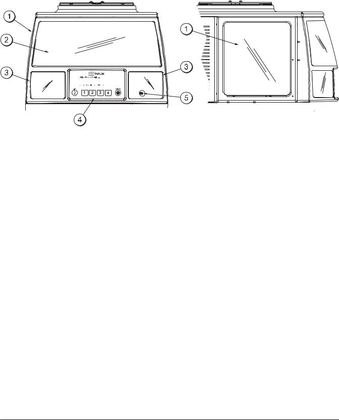
Figure 7 |
|
|
ITEM |
DESCRIPTION |
|
|
1 |
LENS-SIDE |
2 |
LENS-FRONT |
3 |
CARD-FLAVOR |
4 |
CONTROL PANEL |
5 |
POWER SWITCH |
Note: Contact your product supplier or local Taylor Distributor for merchandising graphics.
Power Switch
Remove the right side flavor card lens to place the power switch in the ON position. (See item 5 above.)
When the power switch is placed in the ON position, the large upper display and the side displays will illuminate. The flavor card displays will illuminate when the product is ready to serve. The flavor card lights will flash if an alarm occurs (syrup out, low water pressure, etc.).
Viscosity Adjustment
Each bowl has a viscosity adjustment screw. The left bowl adjustment screw is located on the left side toward the back of the panel. The right bowl adjustment screw is located on the right side toward the back of the panel.
Turn the adjustment screw clockwise to obtain a thicker product, and counterclockwise to obtain a thinner product. Make the adjustments in 1/2 turn increments to achieve proper viscosity.
Model C903 |
11 |
Important: To the Operator |
|
|
|
Display
The C903 display is an eight line by forty character per line LCD (Liquid Crystal Display) with yellow backlighting.
Keypad
The C903 keypad has six keys on a touch sensitive glass panel. These keys are labeled, left to right: info, 1, 2, 3, 4, and cancel. The info key is used to display menu related help text. Keys 1, 2, 3, and 4 are soft keys and their function is defined by the key legends displayed above the keys on line 8 of the LCD. The cancel key is used to exit or back out of menus. The sensitivity or response of the keys can be set in the Set Keypad Sensitivity menu. This sensitivity can be set to quicken or slow the response to touching the keys and to allow wipe down of the display panel without false key triggering.
If a key is pressed continuously, the key will auto-repeat. If a key is held down for more than five seconds, the auto-repeat rate will double.
Flavor Lights
A flavor light is provided for each bowl and is located above the respective bowl. The flavor light is turned on when the product in the bowl is ready to serve.
The flavor light is off if the bowl is not in a serving mode or if the product is not ready to serve. If there is a fault condition that affects a particular side, the flavor light for that side is flashed for four seconds on and four seconds off.
Passcodes
The system will accept two levels of passcodes: Operator (default 2133) and Manager (default 3312). The different levels of passcodes provide different levels of access to menus and menu items. The Operator and Manager passcodes can be changed in the Set Passcode menu.
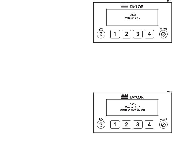
Power Up Initialization Screens
On power up, the model number and firmware version are displayed on the screen for two seconds and the audio alarm is turned on for 50ms (chirp).
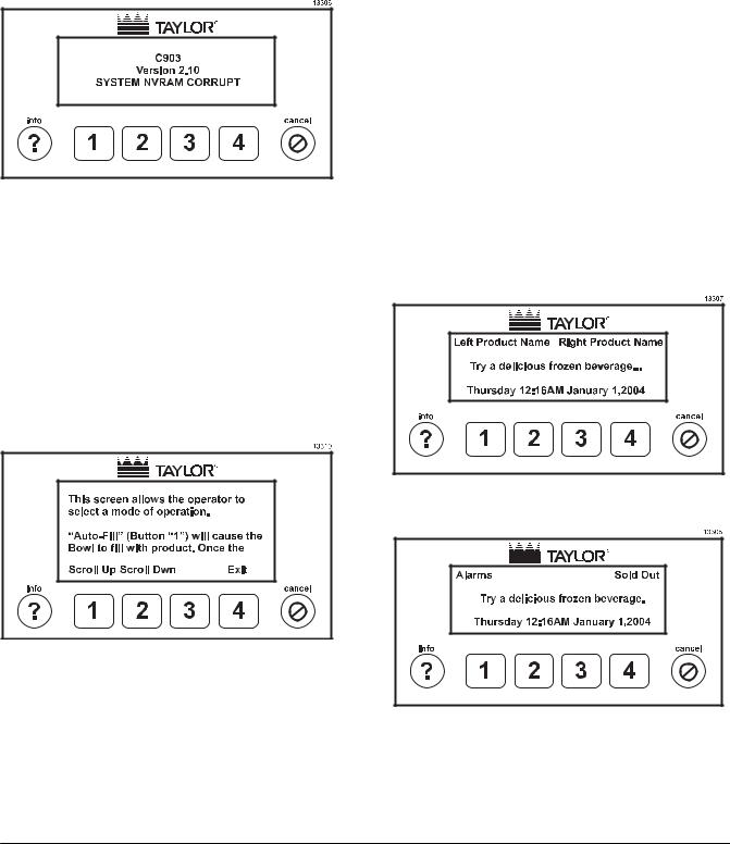
Figure 8
The memory for configuration data is then tested for corruption. Configuration memory holds data that is changed infrequently such as settings entered by the operator. If the configuration memory is found to be corrupted, the screen will display the message “CONFIG NVRAM CORRUPT”. If configuration memory is not corrupted the message “CONFIG NVRAM OK” is displayed.
Audio Alarm
An audio alarm provides an audible tone to alert the operator of alarm conditions and to indicate a keypress. The audio alarm, when active as an alarm, is on for ½ second and off for ½ second. When active as an alarm, the audio alarm can be silenced for 15 minutes by pressing the cancel key when the Marketing screen is being displayed.
Figure 9
Important: To the Operator |
12 |
Model C903 |
|
|
|
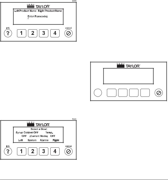
The memory for system data is then tested for corruption. System memory holds data that is changed frequently. If the system memory is found to be corrupted, the screen will display the message “SYSTEM NVRAM CORRUPT”. If system memory is not corrupted the message “SYSTEM NVRAM OK” is displayed.
Figure 10
Operator Menus
Help
Help text is available in all operator and manager accessible menus except the marketing and passcode screens. The help text is brought up by pressing the info key.
Marketing Screen
The marketing screen is displayed after the power up screens. The left product name is displayed on line 1 in the first 20 columns and the right product name is displayed in last 20 columns. On line 4, a marketing message is displayed. On line 8, the day of the week, the time of day, and the date are displayed.
If the unit is a non-RFID unit, the product names will be blank unless product names have been entered by an operator.
If the unit is an RFID unit, the product names are read from the RFID tag on the product boxes. If no box is present, the product name is replaced by the message “NO BOX”.
If there is an alarm condition, the product names are replaced by the message, “Alarms”. If a syrup out or sold out condition occurs, the display will show the message “Syrup Out” or “Sold Out”, respectively, alternating with the message “Alarms”.
Figure 11
Pressing key 1 (Scroll Up) will scroll the text down to display the preceding text (up). Pressing key 2 (Scroll Dwn) will scroll text up to display the following text (down). Pressing key 4 (Exit) or the cancel key will exit the help menu and return to the menu from which the help was called.
Figure 12
Figure 13
If the audio alarm is on, pressing the cancel key will silence the audio alarm for 15 minutes.
Model C903 |
13 |
Important: To the Operator |
|
|
|
The menus are accessed by entering a four digit passcode. Valid passcode keys are keys 1, 2, 3, and 4. If a key, other than the cancel key, is pressed when the Marketing Screen is being displayed, the passcode screen is displayed.
Passcode Menu
Figure 14
An asterisk is displayed for each keypress, including the first keypress from the Marketing Screen. Valid passcode keys are the 1, 2, 3, and 4 keys. If no key is entered for 30 seconds and the passcode entered is not valid, the screen will return to the marketing screen. Pressing the cancel key will return to the Marketing Screen.
If a valid passcode is entered, the Bowl Select Menu will be displayed.
Bowl Select Menu
Figure 15
In the Bowl Select Menu, the product names are displayed on line 1. The syrup cabinet temperature is displayed on line 4. On line 6, the current mode of the left and right bowls is displayed. On line 8, the keypad legends are displayed for keys 1-4. Pressing key 1 will change to the left Select Mode Menu, pressing key 2 will change to the System Menu, and pressing the 4 key will change to the right Select Mode Menu. If there is an alarm active, the legend above key 3 will be Alarm otherwise it will be blank. When the alarm legend is present, pressing key 3 will change to the Alarm Menu. Pressing the cancel key will return to the Marketing Screen.
If the bowl is already in Rinse or Sanitize mode, pressing key 1 (Left) or pressing key 2 (Right) will jump directly to the Rinsing or Sanitizing Menu instead of going to the Bowl Mode Menu.
Bowl Mode Menu
13121
Select a Mode for the Left Bowl.
Current Mode: OFF
|
Auto-Fill |
No-Fill |
Chill |
More |
info |
|
|
|
cancel |
? |
1 |
2 |
3 |
4 |
Figure 16
On line 1, the left and right product names are displayed. On RFID units, this product name is read from the product box. On non-RFID units, the product name must be entered using the Product Name menu. On line 4, the current bowl mode is displayed. On line 8, are the key legends for selecting the mode. Pressing key 1 (Auto-Fill) will place the bowl into Auto-Fill mode. Pressing key 2 (No Fill) will place the bowl into No Fill mode. Pressing key 3 (Chill) will place the bowl into Chill mode. Pressing key 4 (More) will change to the Rinse/Sanitize menu. Pressing the cancel key will return to the Bowl Select Menu.
Important: To the Operator |
14 |
Model C903 |
|
|
|
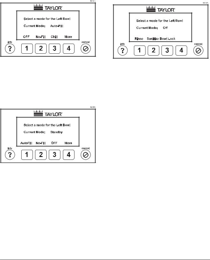
When the bowl is in Auto-Fill, No-Fill, or Chill mode, the respective key legend will show OFF. Pressing a key, when the key legend says OFF, will place the bowl into Off mode.
Figure 17
If a bowl is in Standby mode, the Chill key legend will show OFF. In this case, to place the bowl into Chill mode, the bowl would first have to be placed into Off mode and then can be placed into Chill mode. Only the system can place a bowl into Standby mode. The system will place a bowl into Standby mode during Defrost or because of a fault.
Figure 18
This menu is the same for the right bowl, respectively.
Rinse/Sanitize Menu
Press the MORE (4) key when in the Bowl Mode Screen to go to the Rinse/Sanitize Menu.
Figure 19
From the Rinse/Sanitize Menu, the operator can place the bowl into Rinse Mode, Sanitize Mode, or energize the bowl lock to remove the bowl. A bowl can only be placed into Rinse or Sanitized mode if the bowl mode is Off, Rinsed, or Sanitized and all of the level sensors are exposed.
Pressing key 1 will place the bowl into Rinse Mode and change to the Rinsing Menu.
Pressing key 2 will place the bowl into Sanitize mode and change to the Sanitizing Menu.
Pressing key 3 will raise the bowl lock pin. Pressing key 3 while the bowl lock pin is raised will release the bowl lock pin. When key 3 is pressed and the bowl lock pin is raised, the bowl lock pin will automatically de-energize after 15 seconds if key 3 is not pressed to de-energize the bowl lock pin. The bowl lock key will only respond if the liquid level in the bowl is below the Mix Low sensor.
Pressing the cancel key will return to the Bowl Mode Menu. This menu is the same for the right bowl, respectively.
Model C903 |
15 |
Important: To the Operator |
|
|
|
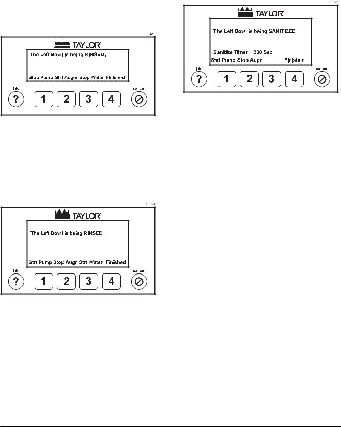
Rinsing Menu
Upon entering this menu, the bowl will have been placed into the Rinse mode, with the syrup pump on, the auger off, and the water on, unless there is a fault that prevents the syrup pump or water from being turned on.
Figure 20
The auger will turn on when the level in the bowl reaches the mix full probe. Pressing key 1 will start and stop the syrup pump. Pressing key 2 will start and stop the auger. Pressing key 3 will start and stop the water. Pressing key 4 will end the Rinse mode and return to the Bowl Mode Menu. Pressing the cancel key will return to the Bowl Select Menu while leaving the bowl in the Rinse mode.
Figure 21
This menu is the same for the right bowl, respectively.
Sanitizing Menu
Figure 22
Upon entering this menu from the Rinse/Sanitize Menu, the bowl will have been placed into the Sanitize mode with the syrup pump on and the auger off, unless there is a fault that prevents the syrup pump from being turned on.
The auger will turn on when the level in the bowl reaches the mix full probe. Pressing key 1 will start and stop the syrup pump. Pressing key 2 will start and stop the auger. Pressing key 4 will end the Sanitize mode and return to the Bowl Mode Menu. Pressing the cancel key will return to the Bowl Select Menu while leaving the bowl in the Sanitize mode.
A Sanitize Timer will count down from 300 seconds to zero. The timer will count down only if the auger is running and the bowl is filled to the Mix Over probe. If a lockout cleaning has been performed, the bowl mode will show “Bowl Cleaned”, otherwise the bowl mode will show “Sanitized”. The system will automatically finish the Sanitizing mode when the 300 seconds (5 minutes) has counted down to 0.
This menu is the same for the right bowl, respectively.
Important: To the Operator |
16 |
Model C903 |
|
|
|
System Menu |
Logged Data Menu |
||||||||||||
|
|
|
|
|
|
|
|
|
|
|
|
|
|
|
|
|
|
|
|
|
|
|
|
|
|
|
|
|
|
|
|
|
|
|
|
|
|
|
|
|
|
|
|
|
|
|
|
|
|
|
|
|
|
|
|
|
|
|
|
|
|
|
|
|
|
|
|
|
|
|
|
|
|
|
|
|
|
|
|
|
|
|
|
|
|
|
|
|
|
|
|
|
|
|
|
|
|
|
|
|
|
|
|
|
|
|
|
|
|
|
|
|
|
|
|
|
|
|
|
|
|
|
|
|
|
|
|
|
|
|
|
|
|
|
|
|
|
|
|
|
|
|
|
|
|
|
|
|
|
|
|
|
|
|
|
|
|
|
|
|
|
|
|
|
|
|
|
|
|
|
|
|
|
|
|
|
|
|
|
|
|
|
|
|
|
|
|
|
|
|
|
|
|
|
|
|
|
|
|
|
|
|
|
|
|
|
|
|
|
|
|
|
|
|
|
|
|
|
|
|
|
|
|
Figure 23
Pressing key 1 (Diagnostic) will change to the Diagnostic Menu. Pressing key 3 (Op Params) will change to the Operator Parameters Menu. Pressing the cancel key will return to the Bowl Select Menu.
Diagnostic Menu
Figure 24
Pressing key 1 (Logged Data) will change to the Diagnostic Menu. Pressing key 2 (Inputs) will change to the Inputs Menu. Pressing key 4 (Refr Mon) will change to the Refrigeration Monitor menu. Pressing the cancel key will return to the Bowl Select Menu.
Figure 25
In the Logged Data Menu, the operator can view the history of faults that the system has logged. Line 2 is the menu title. Line 3 displays the record number with the highest number being the most recent fault. Line 4 displays the side on which the fault occurred. The sides can be Left, Right, or System. System indicates that the fault occurred on a device that is common to both sides such as Low Water Pressure fault. Line 5 displays the timestamp for the fault. Pressing key 1 (Scroll Up) will increment the record number, i.e. display the more recent fault. If the current fault is the last, then key 1 will display the first fault. Pressing key 2 (Scroll Dwn) will decrement the record number, i.e. display the previous fault. If the current fault is the oldest fault, then key 2 will display the last fault. Pressing key 4 (Exit) or the cancel key will exit the menu and return to the Diagnostics Menu.
If there are no faults, the following screen will be displayed.
Figure 26
Model C903 |
17 |
Important: To the Operator |
|
|
|
 Loading...