


C803

Models C801, C801R, F802, P802, C803, C803R, C804
Wendy's Grills
Operating Instructions
072493-M
5/22/09 (Original Publication)
(Updated 6/5/12)


C801/C801R/F802/P802/C803/C803R/C804 Table of Contents
Table of Contents
Section 1 To the Installer 1............................................
Installer Safety 1........................................................
Electrical Connections 1.................................................
Installation 2...........................................................
Setup and Checkout Instructions 3........................................
Ventilation and Clearance 3..............................................
Grease Disposal Container 3.............................................
Section 2 To the Operator 4...........................................
Section 3 Safety 5....................................................
Section 4 Operator Parts Identification 7...............................
C801 7................................................................
C801 Reverse 8........................................................
F802 Front Unit 9.......................................................
P802 Pick Up Window Unit 10.............................................
C803 11................................................................
C803 Reverse 12........................................................
C804 13................................................................
Accessories - Supplied By T aylor Company 14..............................
Accessories Not Supplied By Taylor Company -
Obtain From Wendy's Small Wares Vendors 15..............................
Section 5 Important: To the Operator 16.................................
C801 16................................................................
C801 Reverse 17........................................................
F802 Front Unit 18.......................................................
P802 Pick Up Window Unit 19.............................................

Table of Contents C801/C801R/F802/P802/C803/C803R/C804
Table of Contents - Page 2
C803 20................................................................
C803 Reverse 21........................................................
C804 22................................................................
Section 6 Operating Procedures 26.....................................
Morning Procedures 26...................................................
Operating Procedures 31.................................................
Cook to Order Mode 33...................................................
Nightly Cleaning Procedures 34............................................
Section 7 Troubleshooting Guide 36....................................
Section 8 Warranty Explanation 40......................................
Parts 40................................................................
Labor 40................................................................
Section 9 Parts List 41.................................................
Wiring Diagrams 56......................................................
Note: Continuing research results in steady improvements; therefore, information
in this manual is subject to change without notice.
Note: Only instructions originating from the factory or its authorized translation
representative(s) are considered to be the original set of instructions.
E May, 2009 Taylor (Original Publication)
(Updated June, 2012)
072493-M
The word Taylor and the Crown design
are registered trademarks in the United States
of America and certain other countries.
Taylor Company
750 N. Blackhawk Blvd.
Rockton, IL 61072
1
C801/C801R/F802/P802/C803/C803R/C804 To the Installer
Section 1 To the Installer
The following are general installation instructions.
For complete installation details, please see the
check out card.
Installer Safety
In all areas of the world, equipment should
be installed in accordance with existing local codes.
Please contact your local authorities if you have any
questions.
Care should be taken to ensure that all basic safety
practices are followed during the installation and
servicing activities related to the installation and
service of Taylor equipment.
S Only Taylor authorized service personnel
should perform installation and repairs on
the equipment.
S Authorized service personnel should consult
OSHA Standard 29CFRI910.147 or the
applicable code of the local area for the
industry standards on lockout/tagout
procedures before beginning any installation
or repairs.
S Authorized service personnel must ensure
that the proper PPE is available and worn
when required during installation and
service.
S Authorized service personnel must remove
all metal jewelry, rings, and watches before
working on electrical equipment.
The main power supply(s) to the equipment
must be disconnected prior to performing any
repairs. Failure to follow this instruction may result in
personal injury or death from electrical shock or
hazardous moving parts as well as poor
performance or damage to the equipment.
Note:Allrepairsmustbeperformedbyan
authorized Taylor Service Technician.
This unit has many sharp edges that can
cause severe injuries.
Electrical Connections
Electrical connections to the grill must be provided
and arranged by Wendy's, with their preferred
licensed electrician. This must be completed
immediately following grill installation and prior to the
grill Start Up and Checkout by the local Taylor
representative.
Check the data plate on the grill for voltage, cycle,
phase and electrical specifications. The power
connections are located behind the access cover of
the control box under the front staging side of the
grill.
In the United States, this equipment is intended to
be installed in accordance with the National
Electrical Code (NEC), ANSI/NFPA 70-1987. The
purpose of the NEC code is the practical
safeguarding of persons and property from hazards
arising from the use of electricity. This code contains
provisions considered necessary for safety.
Compliance therewith and proper maintenance will
result in an installation essentially free from hazard!
In all other areas of the world, equipment should be
installed in accordance with the existing local codes.
Please contact your local authorities.
The Proper Wire Size and Branch Circuit
Overcurrent Device shall be selected according to
the data label information and in accordance with
CEC Part I 2006, Section 14-100(e)(i). Incoming
power must be connected to the line side of the
power contactor.
FOLLOW YOUR LOCAL ELECTRICAL CODES!
2
C801/C801R/F802/P802/C803/C803R/C804To the Installer
CAUTION: THIS EQUIPMENT MUST BE
PROPERLY GROUNDED! FAILURE TO DO SO
CAN RESULT IN SEVERE PERSONAL INJURY
FROM ELECTRICAL SHOCK!
This unit is provided with an equipotential
grounding lug that is to be properly attached to the
rear of the frame by the authorized installer. The
installation location is marked by the equipotential
bonding symbol (5021 of IEC 60417-1) on both the
removable panel and the equipments frame.
S Stationary appliances which are not
equipped with a power cord and a plug or
another device to disconnect the appliance
from the power source must have an all-pole
disconnecting device with a contact gap of
at least 3mm installed in the external
installation.
S Appliances that are permanently connected
to fixed wiring and for which leakage
currents may exceed 10 mA, particularly
when disconnected or not used for long
periods, or during initial installation, shall
have protective devices such as a GFI, to
protect against the leakage of current,
installed by the authorized personnel to the
local codes.
S Supply cords used with this unit shall be
oil-resistant, sheathed flexible cable not
lighter than ordinary polychloroprene or
other equivalent synthetic
elastomer-sheathed cord (Code designation
60245 IEC 57) installed with the proper cord
anchorage to relieve conductors from strain,
including twisting, at the terminals and
protect the insulation of the conductors from
abrasion.
Installation
These machines are designed for indoor use
only.
The C801 grill and the C801 Reverse grill must be
lifted and positioned in place with the aid of a lift
device. They are suspended between the adjacent
sandwich counter and the meat well.
The F802,C803, C803 Reverse, and C804 grills are
mounted on carts. They are wheeled into position in
the store.
The P802 grill is installed into the sandwich counter.
The items to be installed / connected by the
distributor include:
S Node board modules
S Lane dividers
S Miscellaneous accessory brackets
DO NOT installthemachineinanarea
where a water jet could be used to clean or rinse the
machine. Failure to follow this instruction may result
in serious electrical shock.
This grill must be installed on a level
surface. Failure to comply may result in personal
injury or equipment damage.
3
C801/C801R/F802/P802/C803/C803R/C804 To the Installer
Setup and Checkout Instructions
Step 1
Install the panels, starting with the bottom. Install the
panels under the node board modules, the lane
dividers (staging side) and the accessory brackets.
Step 2
Install the node board modules.
Step 3
Tighten all screws.
Step 4
Once the electrical connections are completed,
install the box cover and turn the grill on.
Step 5
Wait for 45 minutes for the grill to reach stable
temperatures before proceeding to the next step.
The grill will indicate it is ready to cook in
approximately 15 - 20 minutes.
CAUTION: The grill will be hot. Wear
proper protective equipment to avoid severe burns
from high temperatures.
Step 6
Check the platen lift mechanism and adjust, if
needed (not applicable to P802). (See Lift/Latch
Instructions in the Service Manual.)
Step 7
Install the back panel.
Step 8
The platen should be lowered onto the lower plate
and the gap settings should be properly calibrated.
To close the platen, touch and hold the red button
corresponding to the desired platen. A cook cycle
will not start and the display will read “Standby”.
Release the button after the platen has closed. (See
Platen Gapping Procedures in the Service
Manual.)
Step 9
Once the gaps are set, install the cook side back
splash, lane divider, and the release sheets.
Step 10
Cook one run of product on each platen to check the
product appearance and the finished product
temperature. (Internal temperature must be above
175°F / 79°C.)
Step 11
Check the “cook to order” and back up staging.
Step 12
Fill out the checkout card and the work order /
invoice.
Ventilation and Clearance
To ensure proper operation of this appliance, it must
be installed so that the products of combustion are
efficiently removed.
After set up, do not store anything on top of
the grill. Failure to follow this instruction may result
in a fire hazard.
Grease Disposal Container
In order to comply with NSF Standard 4
requirements, an appropriate grease disposal
container must be provided. This container is
supplied by the KES, not the Taylor Company.

4
C801/C801R/F802/P802/C803/C803R/C804To the Operator
Section 2 To the Operator
The grill you have purchased has been carefully
engineered and manufactured to provide
dependable operation.
This grill, when properly operated and maintained,
will produce a consistent quality product. Like all
mechanical products, they require cleaning and
maintenance. A minimum amount of care and
attention is necessary if the operating procedures in
this manual are followed closely.
This Operator's Manual should be read before
operating or performing any maintenance on your
equipment.
It is strongly recommended that all personnel
responsible for the equipment's operation and
cleaning, review these procedures for proper training
and assurance that no misunderstandings exist.
In the event that you require technical assistance,
please call 877-222-7010 for authorized service.
Note: Warranty is valid only if the parts are
authorized Taylor parts, purchased from an
authorized Taylor Distributor, and the required
service work is provided by an authorized Taylor
service technician. Taylor reserves the right to deny
warranty claims on equipment or parts if
non-approved parts or refrigerant were installed in
the machine, system modifications were performed
beyond factory recommendations, or it is determined
that the failure was caused by neglect or abuse.
Note: Constant research results in steady
improvements; therefore, information in this
manual is subject to change without notice.
If the crossed out wheeled bin symbol is
affixed to this product, it signifies that this product is
compliant with the EU Directive as well as other
similar legislation in effect after August 13, 2005.
Therefore, it must be collected separately after its
use is completed, and cannot be disposed as
unsorted municipal waste.
The user is responsible for returning the product to
the appropriate collection facility, as specified by
your local code.
For additional information regarding applicable local
laws, please contact the municipal facility and/or
local distributor.
5
C801/C801R/F802/P802/C803/C803R/C804 Safety
120605
Section 3 Safety
We at Taylor Company are deeply concerned about
the safety of the operator when he or she comes in
contact with the grill and its parts. Taylor has gone
to extreme efforts to design and manufacture built-in
safety features to protect both you and the service
technician. As an example, warning labels have
been attached to the grill to further point out safety
precautions to the operator.
Please call 877-222-7010 for authorized service.
To Operate Safely:
DO NOT operate the grill without reading
this operator's manual. This manual should be kept
in a safe place for future reference.
Per IEC 60335-1 and its part 2 standards,
“This appliance is to be used only by trained
personnel. It is not intended for use by children or
people with reduced physical, sensory, or mental
capabilities, or lack of experience and knowledge,
unless given supervision or instruction concerning
the use of the appliance by a person responsible for
their safety.”
Failure to follow the instructions below may
result in severe injury or death from electrocution:
S DO NOT operate the grill unless it is
properly grounded.
S DO NOT attempt any repairs unless the
power supply to the grill has been
disconnected (must be performed by an
authorized service technician).
S DO NOT operate the grill unless all service
panels are restrained with screws.
S Stationary appliances which are not
equipped with a power cord and a plug or
other device to disconnect the appliance
from the power source must have an all-pole
disconnecting device with a contact gap of
at least 3 mm installed in the external
installation.
S Appliances that are permanently connected
to fixed wiring and for which leakage
currents may exceed 10 mA, particularly
when disconnected or not used for long
periods, or during initial installation, shall
have protective devices such as a GFI, to
protect against the leakage of current,
installed by the authorized personnel to the
local codes.
S Supply cords used with this unit shall be
oil-resistant, sheathed flexible cable not
lighter than ordinary polychloroprene or
other equivalent synthetic
elastomer-sheathed cord, (Code designation
60245 IEC 57), installed with the proper
cord anchorage to relieve conductors from
strain, including twisting, at the terminals
and protect the insulation of the conductors
from abrasion.
IMPORTANT: DO NOT use a water jet or
spray excessive water on or anywhere near the
grill. Failure to follow this instruction may result in
serious electrical shock and cause permanent
electrical and mechanical damage to internal parts.
Failure to follow this instruction may result in:
S serious electrical shock
S burns from hot steam
S liquid collecting inside the grill and
destroying electrical components.
6
C801/C801R/F802/P802/C803/C803R/C804Safety
DO NOT use cold water or ice to cool the
upper cook surface, the lower cook surface, or the
staging grill plate. Failure to follow this instruction
may result in:
S serious electrical shock
S burns from hot steam
S liquid collecting inside the grill and
destroying electrical components.
Failure to follow the instructions below may
result in severe burns from high temperatures:
S DO NOT prepare or remove product without
proper equipment.
S DO NOT allow untrained personnel to
operate this grill.
S USE EXTREME CAUTION when cleaning
the grill.
Appropriate grill clearance must be
maintained from all combustible materials. Failure to
comply could result in a fire hazard.
Take caution to protect eyes, lungs, and all
parts of the body from potential harm when using
any chemical cleaner. Failure to follow this
instruction may result in a chemical burn.
DO NOT use any abrasives or cleaners
other than approved food service cleaners and
degreasers. Failure to comply may cause illness to
the consumer and may also damage grill surfaces.
This grill must be installed on a level
surface. Failure to comply may result in personal
injury or equipment damage.
NOISE LEVEL: Airborne noise emission does not
exceed 70 dB(A) when measured at a distance of
1.0 meter from the surface of the machine and at a
height of 1.6 meters from the floor.

7
C801/C801R/F802/P802/C803/C803R/C804 Operator Parts Identification
Section 4 Operator Parts Identification
C801
Figure 1
ITEM DESCRIPTION PART NO.
1 HANDLE-ADJUST-PLATEN 070647
2 PLATEN A.-ADJUSTABLE X71825-23
3 HANDLE-LIFT-PLATEN 072711
4 PLATEN A.-4OZ X71824-23
5 PLATEN A.-2OZ X71823-23
ITEM DESCRIPTION PART NO.
6 PANEL A.-SPLASH SHLD W/SP X70783
7 DIVIDER A.-2 LANE 070847
8 DIVIDER A.-3 LANE *STAGE 070848
9 SHIELD-BACKSPLASH 070765
10 DIVIDER A.-COOK 070851
8
C801/C801R/F802/P802/C803/C803R/C804Operator Parts Identification
C801 Reverse
Figure 2
ITEM DESCRIPTION PART NO.
1 DIVIDER A.-3 LANE *STAGE 070848
2 DIVIDER A.-*2 LANE*STAGE 070847
3 PANEL A.-SPLASH SHIELD
W/SPEAKER
X72247
4 PLATEN A.-*C801*2 OZ SERV X71823-23
5 PLATEN A.-*C801* 4 OZ X71824-23
ITEM DESCRIPTION PART NO.
6 PLATEN A.-ADJUSTABLE SERV X71825-23
7 HANDLE-ADJUST-PLATEN 070647
8 HANDLE-LIFT-PLATEN 072711
9 DIVIDER A.-COOK 070851
10 SHIELD-BACKSPLASH 070765
9
C801/C801R/F802/P802/C803/C803R/C804 Operator Parts Identification
F802 Front Unit
Figure 3
ITEM DESCRIPTION PART NO.
1 DIVIDER A.-2 LANE 070847
2 HANDLE-LIFT-PLATEN 072711
3 HANDLE-ADJUST-PLATEN 070647
4 PLATEN A.-SERVICEADJ LEFT X72669-23
ITEM DESCRIPTION PART NO.
5 PLATEN A.-SERVICEADJ X71825-23
6 SHIELD-BACKSPLASH 071732
7 DIVIDER A.-COOK 070851
10
C801/C801R/F802/P802/C803/C803R/C804Operator Parts Identification
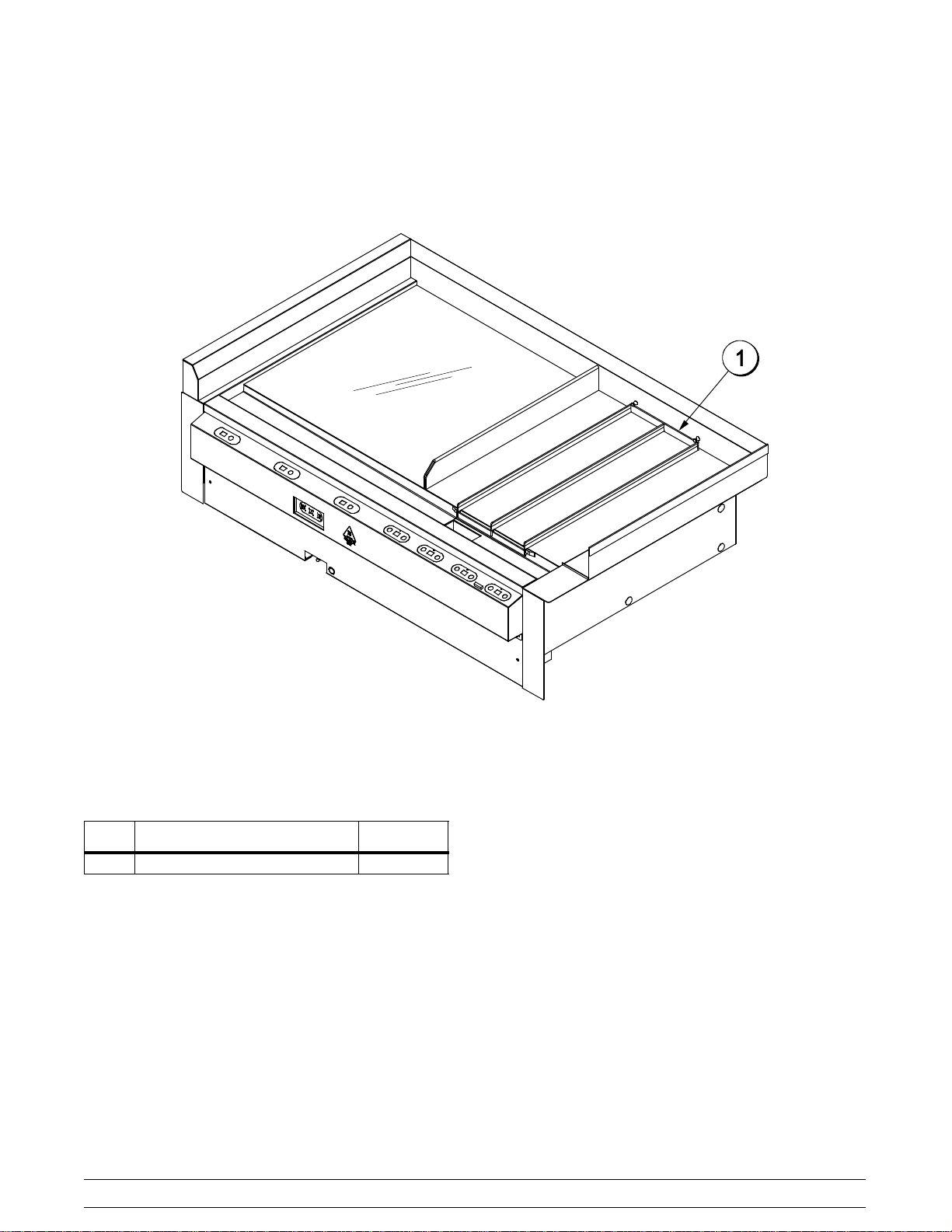
P802 Pick Up Window Unit
Figure 4
ITEM DESCRIPTION PART NO.
1 DIVIDER A.-*2 LANE 070847

11
C801/C801R/F802/P802/C803/C803R/C804 Operator Parts Identification
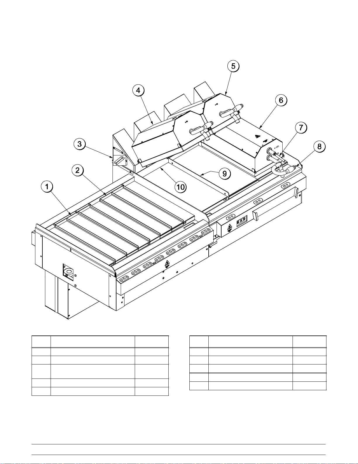
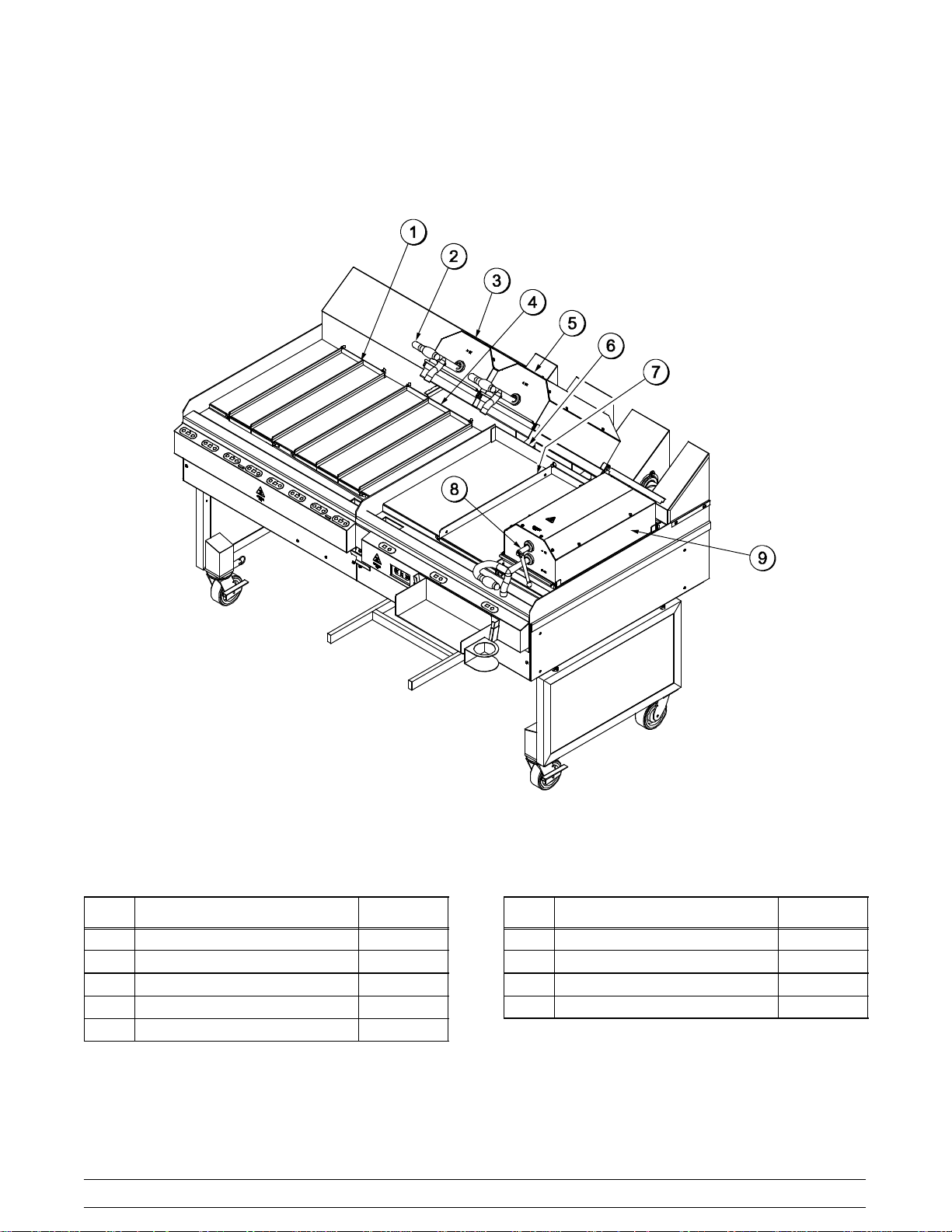
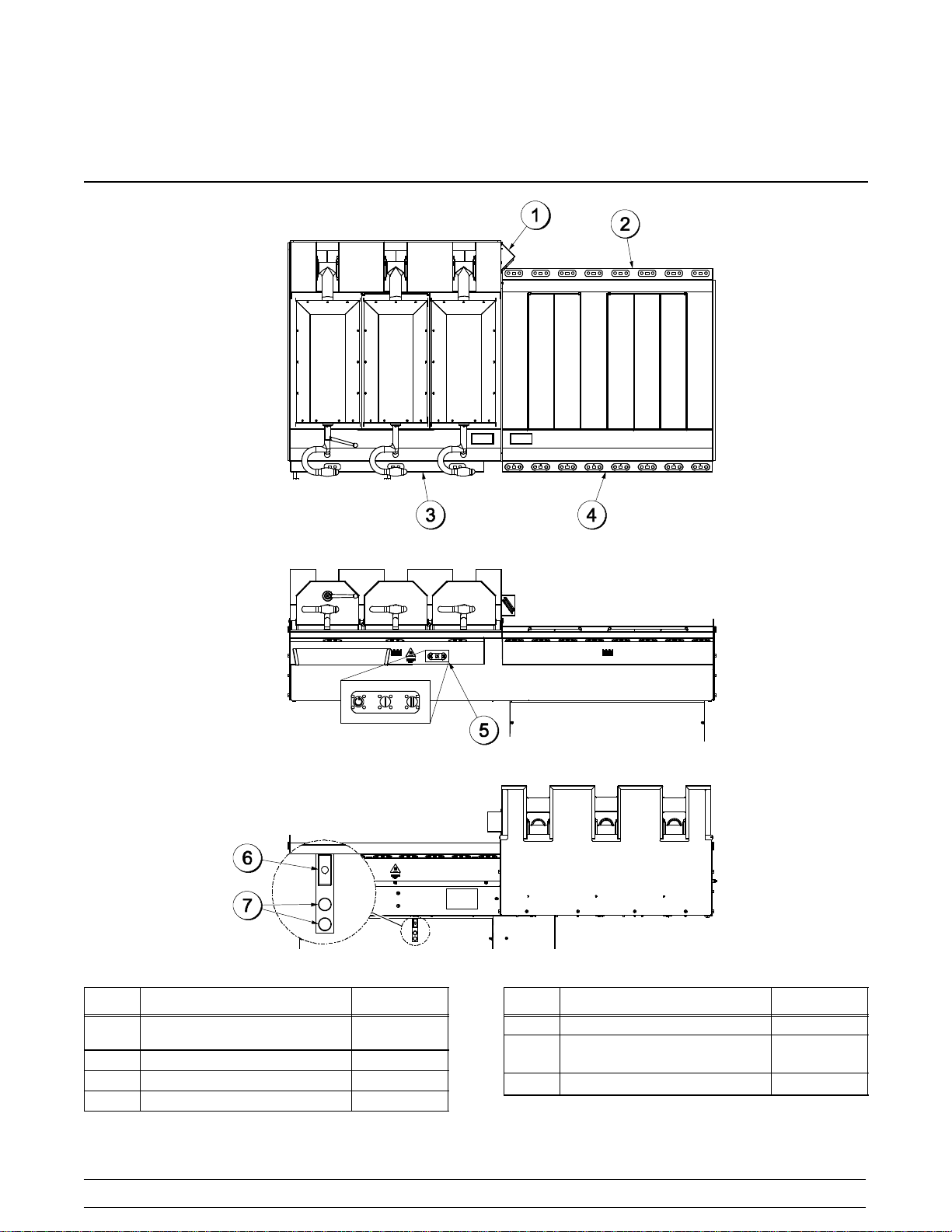
C803
Figure 5
ITEM DESCRIPTION PART NO.
1 HANDLE-LIFT-PLATEN 072711
2 HANDLE-ADJUST-PLATEN 070647
3 PLATEN A.-ADJUSTABLE SERV X71825-23
4 PLATEN A.-*C801*4 OZ SERV X71824-23
5 PLATEN A.-*C801*2 OZ SERV X71823-23
ITEM DESCRIPTION PART NO.
6 SHIELD-BACKSPLASH 070765
7 DIVIDER A.-COOK 070851
8 DIVIDER A.-2 LANE STAGE 070847
9 DIVIDER A.-3 LANE STAGE 070848
12
C801/C801R/F802/P802/C803/C803R/C804Operator Parts Identification
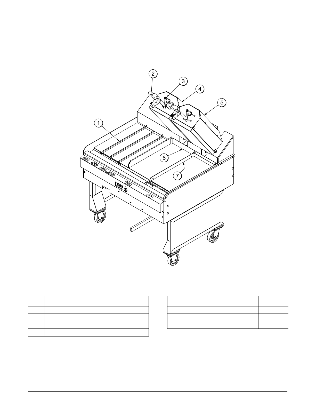
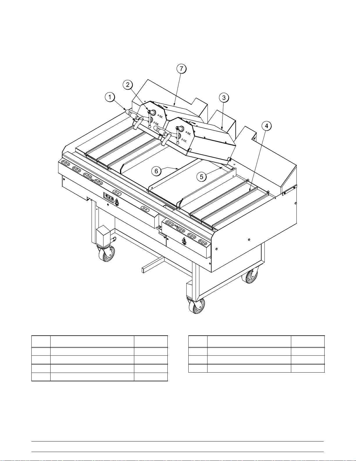
C803 Reverse
Figure 6
ITEM DESCRIPTION PART NO.
1 DIVIDER A.-2 LANE 070847
2 HANDLE-LIFT-PLATEN 072711
3 PLATEN A.-2 OZ X71823-23
4 DIVIDER A.-3 LANE STAGE 070848
5 PLATEN A.-4 OZ X71824-23
ITEM DESCRIPTION PART NO.
6 SHIELD-BACKSPLASH 070765
7 DIVIDER A.-COOK 070851
8 HANDLE-ADJUST-PLATEN 070647
9 PLATEN A.-ADJUSTABLE X71825-23
13
C801/C801R/F802/P802/C803/C803R/C804 Operator Parts Identification
C804
Figure 7
ITEM DESCRIPTION PART NO.
1 HANDLE-LIFT-PLATEN 072711
2 HANDLE-ADJUST-PLATEN 070647
3 PLATEN A.-SERVICE ADJ X71825-23
4 DIVIDER A.-2 LANE 070847
ITEM DESCRIPTION PART NO.
5 SHIELD-BACK SPLASH 071732
6 DIVIDER A.-COOK 070851
7 PLATEN A.-SERVICE ADJ LEFT X72669-23
14
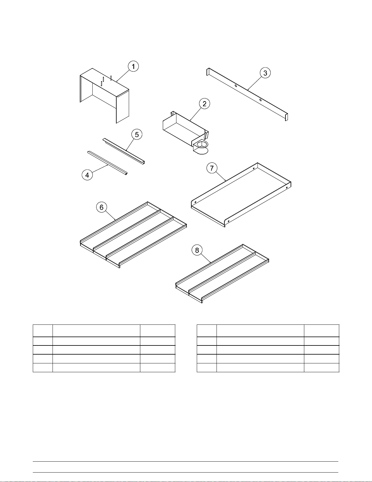
C801/C801R/F802/P802/C803/C803R/C804Operator Parts Identification
Accessories - Supplied By Taylor Company
Figure 8
ITEM DESCRIPTION PART NO.
1 SHIELDA.-LOCATING BUCKET X71284
2 SHELF A.-MEAT LOADING X70944
3 SHIELD-BACKSPLASH 070765
4 CLIP-RELEASE SHEET 070709
ITEM DESCRIPTION PART NO.
5 BRACKET-RELEASESHEET 070707
6 DIVIDER A.-3 LANE *STAGE 070848
7 DIVIDER A. *COOK 070851
8 DIVIDER A. *2 LANE 070847
15
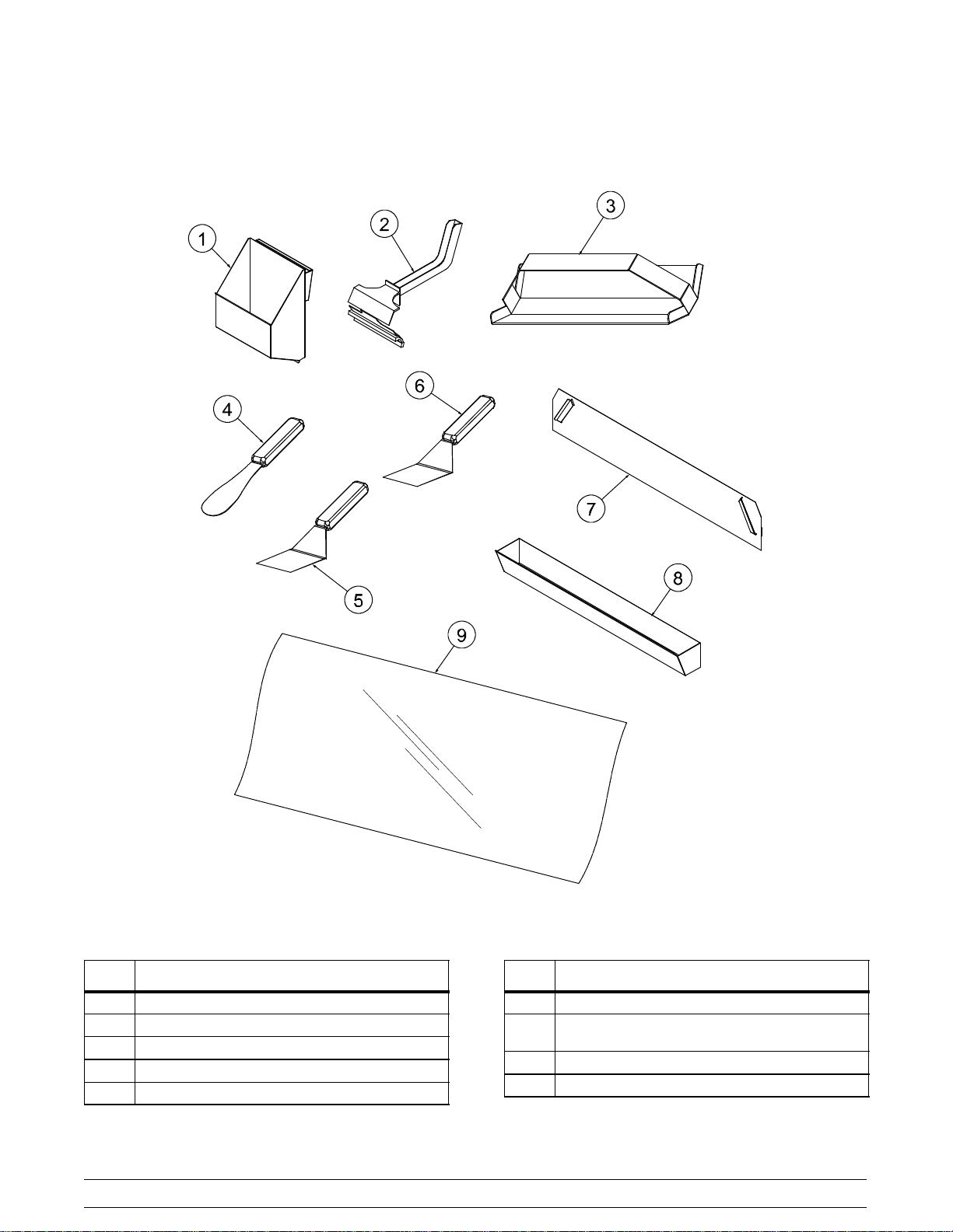
C801/C801R/F802/P802/C803/C803R/C804 Operator Parts Identification
Accessories Not Supplied By Taylor Company -
Obtain From Wendy's Small Wares Vendors
Figure 9
ITEM DESCRIPTION
1 HOLDER-SQUEEGEE
2 HANDLE-SQUEEZE
3 TOOL-TRANSFER
4 SPATULA-REDHANDLE-SERRATED
5 SPATULA-REDHANDLE-SERVING
ITEM DESCRIPTION
6 SPATULA-WHITE HANDLE-SERVING
7 HOLDER-WHITE HANDLED SERVING
SPATULA
8 TROUGH
9 SHEET-RELEASE
16
C801/C801R/F802/P802/C803/C803R/C804Important: To the Operator
Section 5 Important: To the Operator
C801
Figure 10
ITEM DESCRIPTION PART NO.
1 PANEL A.-SPLASH SHIELD
W/SPEAKER
X70783
2 KIT A.-NODE-REAR W/HARN X72136
3 KIT A.-NODE-COOK W/HARN X72134
4 KIT A.-NODE-FRONT W/HARN X72135
ITEM DESCRIPTION PART NO.
5 CONTROL-C801 NODE I/O 071242-SER
6 CONTROL-RESET SWITCH
10A/230
070717
7 LIGHT-RED 230V 070880-27

17
C801/C801R/F802/P802/C803/C803R/C804 Important: To the Operator
C801 Reverse
Figure 11
ITEM DESCRIPTION PART NO.
1 KIT A.-NODE REAR C801
W/HARN
X72136
2 PANEL A.-SPLASH SHIELD
W/SPEAKER
X72247
3 CONTROL-RESET SWITCH
10A/250
070717
4 LIGHT-RED 230V 070880-27
ITEM DESCRIPTION PART NO.
5 NODE A.-COMPLETE C801R
COOK
X72254
6 NODE A.-COMPLETE C801R
STG F
X72243
7 CONTROL C801 MODEI/O 071242-SER
 Loading...