


Models 336, 338, 339, 750, (8)751, (8)754, 774 & 794
TAYLOR COMPANY
a Specialty Equipment company
Rockton, Illinois 61072

Table of Contents
Section 1: Introduction |
1 |
Safety |
2 |
Refrigerant |
2 |
Model 336 Specifications |
3 |
Model 338 Specifications |
4 |
Model 339 Specifications |
5 |
Model 750 Specifications |
6 |
Models 751/8751 Specifications |
7 |
Models 754/8754 Specifications |
8 |
Model 774 Specifications |
9 |
Model 794 Specifications |
10 |
Installation Instructions |
11 |
Running Specifications |
12 |
Section 2: Controls |
13 |
Generation II Control Logic Board |
14 |
Service Tips for Generation II Boards |
19 |
Control Overview |
22 |
Pump Operation |
23 |
Section 3: Troubleshooting |
25 |
General Troubleshooting Guide |
26 |
Troubleshooting Pump Style Freezers |
29 |
Electrical Troubleshooting |
30 |
Section 4: Parts |
31 |
Warranty Explanation |
32 |
Model 336 Exploded View |
33 |
Model 336 Panel Identification |
35 |
Model 338 Exploded View |
37 |
Model 338 Panel Identification |
39 |
Model 339 Exploded View |
41 |
Model 339 Panel Identification |
43 |
Model 750 Exploded View |
45 |
Model 750 Panel Identification |
47 |
Model 751 Exploded View |
49 |
Model 751 Panel Identification |
51 |
Model 754 Exploded View |
53 |
Model 754 Panel Identification |
55 |
Model 774 Exploded View |
57 |
Rail A-Syrup X42541 |
59 |
Model 774 Panel Identification |
60 |
Model 794 Exploded View |
62 |
Model 794 Panel Identification |
64 |
Control A - X38324-27A (Model 336) |
66 |
Control A - X42865-27 (Model 338) |
67 |
Control A - X32963-27A (Models 339 & 754) |
68 |
Control A - X52614-27 (Model 750) |
70 |
Control A - X47194-27A (Models 751/8751) |
71 |
Control A - X42603-27A (Model 774) |
72 |
Control A - X48236-27A (Model 794) |
73 |
Control A - X48237-27 (Model 794) |
74 |
Box A-Cap & Relay - X48535-27 |
75 |
Box A-Cap & Relay - X51593-27 (Model 338) |
76 |
Box A-Cap & Relay - X52665-27 (Model 339) |
77 |
Box A-Cap & Relay - X50317-27 (Model 751) |
78 |
Box A-Cap & Relay - X50297-27 (Model 754) |
79 |
Box A-Cap & Relay - X50373-27 (Model 774) |
80 |
Blower A X47833-27 |
81 |
Switch A-Draw X43417-SER (Model 336) |
82 |
Switch A-Draw X38547 (Models 338, 339, 754, 774, 794) |
83 |
Switch A-Draw X33322-SP (Models 750, 751) |
84 |
Air/Mix Pump-Soft Serve X45316-B |
85 |
Models 336/338/339 Three-Spout Door A |
86 |
Models 750/751 One-Spout Beater Door A |
87 |
Models 754/774/794 Three-Spout Beater Door A |
88 |
Pump A-Syrup 036623 (774) |
89 |
Accessories |
90 |
Parts List |
91 |
Wiring Diagrams |
114 |
CAUTION: Information in this manual is intended to be used by Taylor Authorized Service Technicians only.
Note: Continuing research results in steady improvements; therefore, information in this manual is subject to change without notice.
© January, 1999 Taylor All rights reserved.
Safety
We at Taylor Company, are committed to manufacturing safe operating and serviceable equipment. The many built-in safety features that are part of all Taylor equipment are aimed at protecting operators and trained service technicians alike.
NOISE LEVEL: Airborne noise emission does not exceed 78 dB(A) when measured at a distance of 1.0 meter from the surface of the machine and at a height of 1.6 meters from the floor.
This manual is intended exclusively for Taylor Company authorized service personnel.
Refrigerant
Taylor Company uses R404A refrigerant in the standard softserve freezers. This refrigerant is generally considered non-toxic and non-flammable;
however, any gas under pressure is potentially hazardous.
NEVER fill any refrigerant cylinder completely with liquid. Filling the cylinder to approximately 80% will allow for normal expansion.
Refrigerant liquid sprayed onto the skin may cause serious damage to tissue. Keep eyes and skin protected. If refrigerant burns should occur, flush immediately with cold water. If burns are severe, apply ice packs and contact a physician immediately.
The Taylor Company reminds technicians to be cautious of government laws regarding refrigerant recovery, recycling, and reclaiming systems. If you have any questions regarding these laws, please contact the factory Service Department.
Compressor Warranty Disclaimer
The refrigeration compressor(s) on this machine are warranted for the term indicated on the warranty card accompanying this machine. However, due to the Montreal Protocol and the U.S. Clean Air Act Amendments of 1990, many new refrigerants are being tested and developed; thus seeking their way into the service industry. Some of these new refrigerants are being advertised as drop-in replacements for numerous applications. It should be noted that, in the event of ordinary service to this machine's refrigeration system, only the refrigerant specified on the affixed data label should be used. The unauthorized use of alternate refrigerants will void your compressor warranty. It will be the owners' responsibility to make this fact known to any technicians they employ.
It should be noted, that Taylor does not warrant the refrigerant used in its equipment. For example, if the refrigerant is lost during the course of ordinary service to this machine, Taylor has no obligation to either supply or provide its replacement either at billable or unbillable terms.
The Taylor Company will continue to monitor the industry and test new alternates as they are being developed. Should a new alternate prove, through our testing, that it would be accepted as a drop-in replacement, then the above disclaimer would become null and void. To find out the current status of an alternate refrigerant as it relates to your compressor, call the local Taylor Distributor or the Taylor Factory. Be prepared to provide the model/serial number of the unit in question.
Model 336 Specifications
Freezing Cylinder
Two, 2.8 quart (2.7 liter) volume.
Mix Hopper
Two, 8 quart (7.6 liter) capacity.
Beater Motor
Two, 1.0 hp.
Refrigeration Unit
One, approximately 9,500 btu/hr compressor. Refrigerant R404A.
One independent (SHR) compressor, approximately 400 btu/hr. Refrigerant R134a.
(BTU's may vary based on compressor used.)
Electrical
|
One dedicated connection. |
|
Electrical |
Maximum |
Minimum |
|
Fuse Size |
Circuit Ampacity |
208-230/60/1 Air |
35 |
29 |
|
|
|
208-230/60/1 Water |
35 |
26 |
208-230/60/3 Air |
25 |
21 |
208-230/60/3 Water |
25 |
18 |
This unit is manufactured in other electrical characteristics. Refer to the Distributor Data Book for availability. (For exact electrical information, always refer to the data label of the unit.)
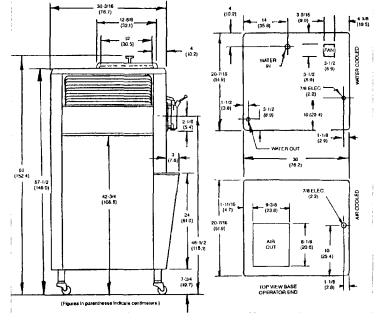
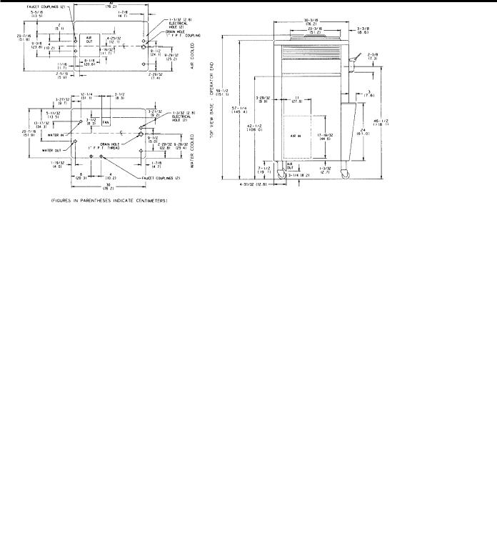
Air Cooled
Clearance: 3" (7.6 cm.) around all sides. A deflector has been added to underside, preventing recirculation of warm air. This will assure proper air flow across condensers to obtain optimum performance.
Water Cooled
Water inlet and drain connections under side of base 3/8" FPT
Dimensions
Width: 20-7/16" (51.9cm.)
Depth: 33-3/16" (84.3cm.) Height: 60" (152.4 cm.)
Floor Clearance: 7-3/4" (19.7 cm.) mounted on standard casters.
Approximate Weights
Net: 575 Ibs. (260.8 kgs.) Crated: 628 Ibs. (284.9 kgs.),
39.1 cu.ft. (1.10cu.m.)
Availability and specifications are subject to change without notice.
This unit is designed and constructed to meet stringent safety and sanitation requirements for NSF and UL.

Model 338 Specifications
Freezing Cylinder
Two, 2.8 quart (2.7 liter) volume.
Mix Hopper
Two, 20 quart (18.9 liter).
Beater Motor
Two, 1.0 hp.
Refrigeration Unit
One, approximately 9,500 btu/hr compressor. Refrigerant R404A.
One independent (SHR) compressor, approximately 400 btu/hr. Refrigerant R134a. (BTU's may vary based on compressor used.)
Electrical
|
One dedicated connection. |
|
Electrical |
|
|
Maximum |
Minimum |
|
|
Fuse Size |
Circuit Ampacity |
208-230/60/1 Air |
35 |
28 |
208-230/60/1 Water |
35 |
28 |
208-230/60/3 Air |
25 |
19 |
208-230/60/3 Water |
25 |
19 |
This unit is manufactured in other electrical characteristics. Refer to the Distributor Data Book for
availability. (For exact electrical information, always refer to the data label of the unit.)
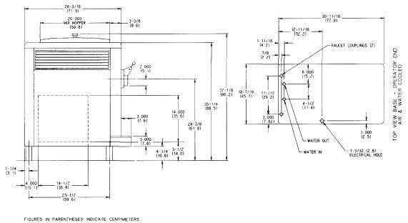
Air Cooled
Clearance: 6" (15.2 cm.) on both sides. It is recommended to install a skirt to one side of the unit, and to place the back of the unit against a wall. This will assure proper air flow across condensers to obtain optimum performance.
Water Cooled
Water inlet and drain connections under side of base 3/8" FPT.
Dimensions
Width: 26-7/16" (67.2 cm.) Depth: 31-3/16" (79.2 cm.) Height: 38-3/4" (98.4 cm.)
Counter Clearance: 3-1/2" (8.9 cm.) mounted on standard legs.
Approximate Weights
Net: 465 Ibs. (219.0kgs.) Crated: 542 Ibs. (245.9 kgs.), 29.9 cu. ft. (.84 cu. m.)
Availability and specifications are subject to change without notice.
This unit is designed and constructed to meet stringent safety and sanitation requirements for NSF and UL.

Model 339 Specifications
Freezing Cylinder
Two, 2.8 quart (2.7 liter) volume.
Mix Hopper
Two, 20 quart (18.9 liter) capacity.
Beater Motor
Two, 1.0 hp.
Refrigeration Unit
Two, approximately 6,000 btu/hr compressors. Refrigerant R404A.
One independent (SHR) compressor, approximately 400 btu/hr. Refrigerant R134a.
(BTU's may vary based on compressor used.)
Electrical
|
Two dedicated connections. |
||||
Electrical |
Maximum |
Minimum Circuit |
|||
Fuse Size |
Ampacity |
||||
|
|||||
|
Left |
Right |
Left |
Right |
|
208-230/60/1 Air |
25 |
20 |
19 |
14 |
|
208-230/60/1 Water |
20 |
20 |
16 |
14 |
|
208-230/60/3 Air |
20 |
15 |
16 |
12 |
|
208-230/60/3 Water |
20 |
15 |
14 |
12 |
|
This unit is manufactured in other electrical characteristics. Refer to the Distributor Data Book for
availability. (For exact electrical information, always refer to the data label of the unit.)
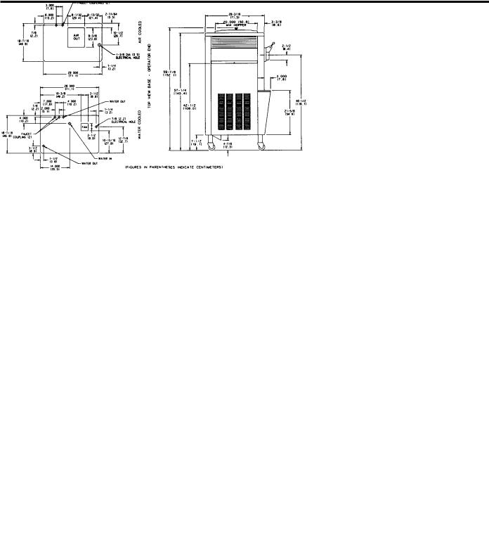
Air Cooled
Clearance: 3" (7.6 cm.) around all sides. A deflector has been added to underside preventing recirculation of warm air. This will assure proper air flow across condensers to obtain optimum performance.
Water Cooled
Water inlet and drain connections under side of base 1/2" FPT.
Dimensions
Width: 26-7/16" (67.2 cm.) Depth: 33" (83.8 cm.) Height: 59-7/8" (152.1 cm.)
Floor Clearance: 7-1/2" (19.1 cm.) mounted on standard casters.
Approximate Weights
Net: 608 Ibs. (275.8 kgs.) Crated: 698 Ibs. (316.6 kgs.), 48.1 cu. ft. (1.3 cu. m.)
Availability and specifications are subject to change without notice.
This unit is designed and constructed to meet stringent safety and sanitation requirements for NSF and UL
Model 750 Specifications
Freezing Cylinder
One, 3.4 quart (3.2 liter) volume.
Mix Hopper
One, 20 quart (18.9 liter) capacity.
Beater Motor
One, 1.5hp.
Refrigeration Unit
One, approximately 4,900 btu/hr compressor. Refrigerant R404A.
One independent (SHR) compressor, approximately 400 btu/hr. Refrigerant R134a. (BTU's may vary based on compressor used.)
Electrical
|
One dedicated connection. |
|
Electrical |
Maximum |
Minimum |
|
Fuse Size |
Circuit Ampacity |
208-230/60/1 Air |
20 |
18 |
208-230/60/1 Water |
20 |
18 |
208-230/60/3 Air |
15 |
12 |
208-230/60/3 Water |
15 |
12 |
This unit is manufactured in other electrical characteristics. Refer to the Distributor Data Book for
availability. (For exact electrical information, always refer to the data label of the unit.)
Air Cooled
Clearance: 6" (15.2 cm.) on both sides. It is recommended to place the back of the unit against a wall. This will assure proper air flow across condensers to obtain optimum performance.
Water Cooled
Water inlet and drain connections 3/8" FPT.
Dimensions
Width: 18-7/16" (46.8cm.)
Depth: 31-3/16" (79.2cm.) Height: 37-7/8" (96.2 cm.)
Counter Clearance: 4-1/2" (10.8 cm.) mounted on standard legs.
Approximate Weights
Net: 360 Ibs. (163.3 kgs.) Crated: 410 Ibs. (186.0 kgs.), 29.1 cu. ft. (.81 cu. m.)
Availability and specifications are subject to change without notice.
This unit is designed and constructed to meet stringent safety and sanitation requirements for NSF and UL.
Models 751/8751 Specifications
Freezing Cylinder
One, 3.4 quart (3.2 liter) volume.
Mix Hopper
One, 20 quart (18.9 liter) capacity.
Beater Motor
One,1.5 hp.
Refrigeration Unit
One, approximately 9,500 btu/hr compressor. Refrigerant R404A.
One independent (SHR) compressor, approximately 400 btu/hr. Refrigerant R134a.
(BTU's may vary based on compressor used.)
Electrical
Electrical |
One dedicated connection. |
|
Model 751 |
Maximum |
Minimum |
Fuse Size |
Circuit Ampacity |
|
208-230/60/1 Air |
35 |
26 |
208-230/60/1 Water |
30 |
24 |
208-230/60/3 Air |
25 |
19 |
208-230/60/3 Water |
20 |
17 |
Model 8751 |
|
|
208-230/60/1 Air |
35 |
28 |
208-230/60/1 Water |
35 |
25 |
208-230/60/3 Air |
25 |
21 |
208-230/60/3 Water |
25 |
18 |
These units are manufactured in other electrical characteristics. Refer to the Distributor Data Book for availability. (For exact electrical information, always refer to the data label of the unit.)
Air Cooled
Clearance: 3" (7.6 cm.) around all sides. A deflector has been added to underside preventing recirculation of warm air. This will assure proper air flow across condensers to obtain optimum performance.
Water Cooled
Water inlet and drain connections 3/8" FPT.
Dimensions
Width: 18-7/16" (46.8cm.) Depth: 31-3/16" (79.2 cm.) Height: 59-7/8" (152.1 cm.)
Floor Clearance: 7-1/2" (19.1 cm.) mounted on standard casters.
Approximate Weights
Model 751:
Net: 455 Ibs. (201.9 kgs.) Crated: 476 Ibs. (215.9 kgs.), 35.4 cu. ft. (.99 cu. m.)
Model 8751:
Net: 480 Ibs. (217.7 kgs.) Crated: 501 Ibs. (227.2 kgs.),
35.4 cu. ft. (.99 cu. m.)
Availability and specifications are subject to change without notice.
These units are designed and constructed to meet stringent safety and sanitation requirements for NSF and UL.

Models 754/8754 Specifications
Freezing Cylinder
Two, 3.4 quart (3.2 liter) volume.
Mix Hopper
Two, 20 quart (18.9 liter) capacity.
Beater Motor
Two, 1.5 hp.
Refrigeration Unit
Two, approximately 9,500 btu/hr compressors. Refrigerant R404A.
One independent (SHR) compressor, approximately 400 btu/hr. Refrigerant R134a.
(BTU's may vary based on compressor used.)
Electrical
Electrical |
Two dedicated connections. |
|||
Maximum |
Minimum Circuit |
|||
|
Fuse Size |
Ampacity |
||
Model 754 |
Left |
Right |
Left |
Right |
208-230/60/1 Air |
35 |
30 |
26 |
22 |
208-230/60/1 Water |
30 |
30 |
24 |
22 |
208-230/60/3 Air |
25 |
20 |
19 |
15 |
208-230/60/3 Water |
20 |
20 |
17 |
15 |
Model 8754 |
|
|
|
|
208-230/60/1 Air |
35 |
30 |
28 |
24 |
208-230/60/1 Water |
35 |
30 |
25 |
24 |
208-230/60/3 Air |
25 |
20 |
21 |
17 |
208-230/60/3 Water |
25 |
20 |
18 |
17 |
These units are manufactured in other electrical characteristics. Refer to the Distributor Data Book for availability. (For exact electrical information, always refer to the data label of the unit.)
Air Cooled
Clearance: 3" (7.6 cm.) around all sides. A deflector has been added to underside preventing recirculation of warm air. This will assure proper air flow across condensers to obtain optimum performance.
Water Cooled
Water inlet and drain connections under side of base 1/2" FPT.
Dimensions
Width: 26-7/16" (67.2 cm.) Depth: 33" (83.8 cm.) Height: 59-7/8" (152.1 cm.)
Floor Clearance: 7-1/2" (19.1 cm.) mounted on standard casters.
Approximate Weights
Model 754:
Net: 680 Ibs. (308.4 kgs.) Crated: 707 Ibs. (320.7 kgs.), 47.3 cu. ft. (1.34 cu. m.)
Model 8754:
Net: 730 Ibs. (331.1 kgs.) Crated: 768 Ibs. (348.4 kgs.),
47.3 cu. ft. (1.34 cu. m.)
Availability and specifications are subject to change without notice.
These units are designed and constructed to meet stringent safety and sanitation requirements for NSF and UL.
Model 774 Specifications
Freezing Cylinder
Two, 3.4 quart (3.2 liter) volume.
Mix Hopper
Two, 20 quart (18.9 liter) capacity.
Beater Motor
Two, 1.5 hp.
Refrigeration Unit
Two, approximately 9,500 btu/hr compressors. Refrigerant R404A.
One independent (SHR) compressor, approximately 400 btu/hr. Refrigerant R134a.
(BTU's may vary based on compressor used.)
Electrical
|
Two dedicated connections. |
||||
Electrical |
Maximum |
Minimum Circuit |
|||
Fuse Size |
Ampacity |
||||
|
|||||
|
Left |
Right |
Left |
Right |
|
208-230/60/1 Air |
35 |
30 |
28 |
22 |
|
208-230/60/1 Water |
35 |
30 |
25 |
22 |
|
208-230/60/3 Air |
25 |
20 |
21 |
15 |
|
208-230/60/3 Water |
25 |
20 |
18 |
15 |
|
This unit is manufactured in other electrical characteristics. Refer to the Distributor Data Book for
availability. (For exact electrical information, always refer to the data label of the unit.)
Air Cooled
Clearance: 3" (7.6 cm.) around all sides. A deflector has been added to underside preventing recirculation of warm air. This will assure proper air flow across condensers to obtain optimum performance.
Water Cooled
Water inlet and drain connections under side of base 1/2" FPT.
Dimensions
Width: 26-7/16" (67.2 cm.) Depth: 36-3/16" (91.9cm.) Height: 59-7/8" (152.1 cm.)
Floor Clearance: 7-1/2" (19.1 cm.) mounted on standard casters.
Approximate Weights
Net: 760 Ibs. (344.7 kgs.) Crated: 865 Ibs. (392.4 kgs.), 49.7 cu. ft. (1.3 cu. m.)
Availability and specifications are subject to change without notice.
This unit is designed and constructed to meet stringent safety and sanitation requirements for NSF and UL.
Model 794 Specifications
Freezing Cylinder
Two, 3.4 quart (3.2 liter) volume.
Mix Hopper
Two, 14 quart (13.3 liter) capacity.
Beater Motor
Two, 1.5 hp.
Refrigeration Unit
Two, approximately 9,500 btu/hr compressors. Refrigerant R404A.
One independent (SHR) compressor, approximately 400 btu/hr. Refrigerant R134a.
(BTU's may vary based on compressor used.)
Electrical
|
Two dedicated connections. |
||||
Electrical |
Maximum |
Minimum Circuit |
|||
Fuse Size |
Ampacity |
||||
|
|||||
|
Left |
Right |
Left |
Right |
|
208-230/60/1 Air |
35 |
35 |
28 |
23 |
|
208-230/60/1 Water |
35 |
35 |
25 |
23 |
|
208-230/60/3 Air |
25 |
20 |
20 |
16 |
|
208-230/60/3 Water |
25 |
20 |
17 |
16 |
|
This unit is manufactured in other electrical characteristics. Refer to the Distributor Data Book for
availability. (For exact electrical information, always refer to the data label of the unit.)
Air Cooled
Clearance: 3" (7.6 cm.) around all sides. A deflector has been added to underside preventing recirculation of warm air. This will assure proper air flow across condensers to obtain optimum performance.
Water Cooled
Water inlet and drain connections under side of base 1/2" FPT.
Dimensions
Width: 20-7/16" (51.9cm.) Depth: 33-3/16" (84.3 cm.) Height: 59-1/2" (151.1 cm.)
Floor Clearance: 7-1/2" (19.1 cm.) mounted on standard casters.
Approximate Weights
Net: 690 Ibs. (312.9kgs.) Crated: 747 Ibs. (338.8 kgs.), 39.1 cu. ft. (1.1 cu. m.)
Availability and specifications are subject to change without notice.
This unit is designed and constructed to meet stringent safety and sanitation requirements for NSF and UL.
Installation Instructions
Air Cooled Units
Air cooled units require a minimum of 3" (7.6 cm.) of clearance around all sides of the freezer (6" [15.2 cm] for Models 338 and 750). Failure to allow for adequate clearance can reduce the refrigeration capacity of the freezer and possibly cause damage to the compressor.
Water Cooled Units
A cold water supply must be provided with a hand shut-off valve. Refer to the "Specifications" section in this manual to identify inlet and outlet water connections for the condensers. (See "Specifications" pages 3 through 10 for proper line sizes.) If there is more than one unit, larger lines should be used. (Flexible lines are recommended if local codes permit.) The water lines must be flushed of foreign substances before connection. Depending on local water conditions, it may be advisable to install a water strainer to prevent foreign substances from clogging the water system. After connecting the inlet water line, install a flexible drain line to an open trap drain. An open trap drain is used so that drain water flow can be observed. Do not install a shut-off valve on the drain line. Incorrect hook-up will result in continuous water flow through the lines.
Recommended water pressure supplied to the unit is 35PSI (241.3kPa).
Electrical Connections
Each freezer requires a dedicated power supply. Check the data label on the freezer for fuse, circuit ampacity and electrical specifications. Refer to the wiring diagram, provided inside the control box, for proper power connections.
This equipment is intended to be installed in accordance with the National Electric Code (NEC), NFPA 70. The purpose of this code is the practical safeguarding of persons and property from hazards arising from the use of electricity. This code contains provisions considered necessary for safety. Compliance therewith and proper maintenance will result in an installation essentially free from hazard.
CAUTION: THIS EQUIPMENT MUST BE PROPERLY GROUNDED! FAILURE TO DO SO CAN RESULT IN SEVERE PERSONAL INJURY FROM ELECTRICAL SHOCK!
FOLLOW YOUR LOCAL ELECTRICAL CODES!
Beater Rotation
Beater rotation must be clockwise as viewed looking into the freezing cylinder.
Figure 1.
To correct rotation on a single-phase unit, exchange leads inside the beater motor. (Follow the diagram printed on the motor.)
To correct rotation on a three phase unit, exchange leads at the main terminal block (splice box).
CAUTION: Make sure the power switch is in the OFF position before correcting the beater rotation. Failure to do so may result in electrocution or component damage.
Electrical connections are made directly to the terminal block provided in the control box.

Running Specifications
Pressures/Temperatures
The following are the Taylor Company recommended settings for various components within these models. All freezers in this manual use Refrigerant HP62 (R404A).
Expansion Valve Soft
Serve
Air Cooled - 21 psi. (145 kPa)
Water Cooled - 20 to 22 psi. (138 to 152 kPa) for a normal product of 16° to 18°F. (-8.8°to -7.7° C.).
Expansion Valve Adjustment
Place your gauge on the access valve on the suction line (located at the compressor).
Adjust the pressure higher or lower by turning the adjustment screw. Clockwise turns will raise the pressure and counterclockwise turns will lower the pressure.
Note: Make expansion valve adjustments with mix in the cylinder and the freezer in the AUTO mode. Be sure to allow adequate time for the pressure to stabilize.
Important: On the Models 336 and 338, expansion valves on each side of the unit must be set separately. Pressures must be set at 4 PSI (28 kPa) lower than what is indicated on the tag.
Low Side (Suction)
Suction pressure equals the expansion valve setting.
High Side (Discharge)
High side pressure varies for air cooled units, depending on the ambient temperature.
Ambient Temperature |
Normal Operating Head |
||
Pressures |
|||
|
|
||
|
|
|
|
F. |
C. |
PSI |
|
|
|
|
|
70° |
21.1° |
240 - 270 |
|
|
|
(1,655 - 1,862 kPa) |
|
|
|
|
|
80° |
26.7° |
270 - 300 |
|
|
|
(1,862 - 2,069 kPa) |
|
|
|
|
|
90° |
32.2° |
300 - 340 |
|
|
|
(2,069 - 2,344 kPa) |
|
100° |
37.8° |
340 - 380 |
|
|
|
(2,344 - 2,620 kPa) |
|
|
|
|
|
Water Valve
On a water cooled unit, the water valve should be set to maintain a compressor head pressure of 255 psi. (1,758kPa).
Water Valve Adjustment
Place your gauge on the high side access port of the compressor. Turning the adjustment stem on the water valve clockwise will lower the pressure.
Note: Make this adjustment with mix in the cylinder and the freezer in the AUTO mode. Be sure to allow adequate time for pressure to stabilize.
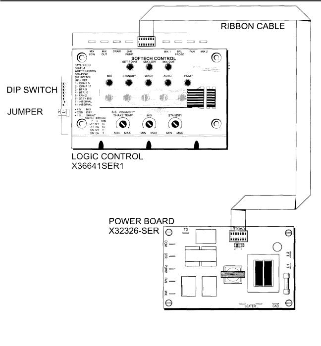
Generation II Control Logic Board
The Generation II logic board's primary function is to interpret modes of operation. The board monitors mix levels and temperatures by sending commands to the control's power board. Commands are sent via a ribbon cable, enabling the proper relays on the power board to open or close. (See illustration on page 22.)
Function:
Interpret a mode of operation/monitor mix level and temperature/monitor product viscosity or product temperature and send a command to the power board through a ribbon cable enabling the proper relays on the power board to be open or closed.
Logic Board (Part Numbers):
The part number for the Generation I logic board is X32325-SER.
As of July, 1996 we have modified the differential on Generation II controls from 13'F/7.2'Cto4.5'F/2.5-C in order to meet the new NSF mix temperature requirements. The new control has a shunt (jumper) to select proper temperatures. This shunt is located beneath the dip switches on the left side of the control. The shunt is set in the upper position for 4.5*F/2.5'C differential for use on mix hopper systems and in the lower position for 13' F/7.2-C differential for use on mix cabinet systems. The new control is compatible with older units. This change will require new part numbers as follows:
Old Part No. |
New Part No. |
X36641-SERGen. II |
X36641SER1 |
X38523-SER Gen. ll-W/Chime |
X38523SER1 |
X41072-SER Gen. II-W/EVC |
X41072SER1 |
X42002-SER Gen. ll-Hopper Pump |
X42002SER1 |
Power Board (Part Numbers):
X32326-SER - Soft Serve
X34983-SER - Shake
Thermistor Probes:
There are three types of thermistor probes used on softech freezers. The resistance value of the thermistor probes corresponds with the temperature. As the temperature becomes warmer, the probe resistance decreases.
X31602 |
- Barrel Probe (Senses product in |
|
freezing cylinder.) |
X34466 |
- Hopper Probe (Senses temperature |
|
of mix in hopper.) |
X50717 |
- Hopper (Senses temperature of mix in |
|
hopper with new Generation II.) |
X36267 |
- Cabinet Probe (Senses mix cabinet |
|
air temperature.) |
Approximate probe resistance readings:
10,000 OHMS at room temperature (77°F/25°C).
30,035 OHMS at hopper/cabinet temperature (35°F/2°C).
38,830 OHMS at shake temperature (26°F/-3.3°C). 48,636 OHMS at soft service temperature (18°F/-7.7°C).
Viscosity Function:
In soft serve freezers the logic board monitors amp draw on the beater motor, which is directly related to the viscosity of the product in the freezing cylinder. When the amp draw reaches its set point, the unit cycles off. Therefore, the viscosity of the product will always be consistent even through its temperature may vary slightly.
To monitor amperage, L1 power supplied to the beater motor must pass through the power board beater terminals. The same softech controls are used in both single and three phase applications. For this reason the control must be set to operate in an amperage range which relates to the beater motor amperage and the desired product viscosity setting.
The selected amperage range simply determines the adjustment span of the viscosity adjustment potentiometer on the logic board. The jumper on the power board determines the amperage range selection. The jumper is placed on the pin which corresponds to the beater motor amperage when the desired product viscosity is attained. See page 22 to locate the range selection jumper.
Viscosity Control Range Selections:
2.4 PIN- 1.2 AMP to 2.4 AMP
5.0 PIN - 2.5 AMP to 5.0 AMP
8.0 PIN - 4.0 AMP to 8.0 AMP 11.2PIN - 5.7 AMP to 11.2 AMP
Setting Viscosity Adjustment:
1.Place an amp probe on one of the L1 leads on the beater terminal on the power board.
2.Turn the viscosity adjustment screw to the "MAX" position.
3.With the freezer properly primed, actuate the refrigeration cycle (press "AUTO").
4.During the freezing process, draw a sample and inspect the product appearance. When desired product viscosity and appearance is achieved, note the beater motor amperage.
5.Cancel the refrigeration cycle (press "AUTO").
6.Using the chart, set what range the beater motor amperage falls into and place the jumper on the proper pin. (Note: See chart above for amperage range.)
7.Press "AUTO". When amperage achieves the previously noted beater motor amperage, turn the viscosity adjustment screw counterclockwise slowly until the unit cycles off.
8.Draw several samples to verify that the amperage at cycle off and product quality remains consistent.
Mix Adjustment:
The mix setting is the temperature adjustment for the mix cabinet or the mix hopper.
Ideal mix temperature = 38°F (3.3°C) to 40°F (4.4°C).
Cut-out temperature will always be 13°F (7.2°C) (cabinet)/4.5° F (2.5°C) (hopper) lower than the cut-in temperature. (See SB 2474.)
The range for cut-in temperature is "MIN" approximately 52'F (11.0'C) and "MAX" approximately 36*F (2.2'C).
Setting the Mix Cabinet Temperature:
1.Place a thermometer in the cabinet close to the thermistor probe.
2.Turn the mix adjustment screw all the way to "MAX".
3.When the air temperature in the cabinet reaches 30° F to 31 °F (-1.1 °C), turn the mix adjustment screw counterclockwise until the mix refrigeration cycles off.
4.Allow the mix temperature to stabilize and adjust the setting if necessary.
Setting the Mix Hopper Temperature
1. To set the mix hopper temperature, fill the
hopper at least half full with approximately 40° F (4.4°C) mix.
2.Install a suction pressure gauge at the EPR valve (evaporator pressure regulator) and verify the correct operating pressure. Adjust if necessary.
3.Set the "MIX" potentiometer to mid-range.
4.Allow the mix hopper refrigeration system to cycle until the mix temperature is stabilized. Adjust the setting if necessary.
Note: On the Models 336, 338, 339, 754 and 794, the temperature adjustment must be made on the left logic board.
Standby Adjustment
Maintains mix temperature in the freezing cylinder during long "no sale" periods to prevent over-beating of the product.
Ideal standby temperature = 30°F (1.1 °C) to 35°F (1.7°C).
Cut-out temperature will always be 4°F (2°C) lower than the cut-in temperature.
The range for cut-in temperature is "MIN" approximately 44'F (6.6'C) and "MAX" approximately 30-F (-1,1'C).
Setting Standby Temperatures
1.With the unit properly primed with fresh mix, turn the STANDBY adjustment screw to the warmest position.
2.Press "STANDBY".
3.When the main refrigeration system cycles off, draw a sample portion and check the product temperature.
4.To get the desired standby temperature, make a slight clockwise adjustment and wait until the main refrigeration cycles off.
Note: On pump units, "STANDBY" must be cancelled and "PUMP" must be pressed to replace the portion which was used for the sample draw.
Thermistor Curve
When checking a thermistor probe, first determine the present temperature at the probe and find it on this chart along with the approximate correct ohmmeter reading. The ohmmeter reading may vary from the
F.° |
C.° |
K OHM |
|
|
|
-10 |
-23.3 |
118.201 |
-9 |
-22.7 |
114.394 |
-8 |
-22.2 |
110.709 |
-7 |
-21.6 |
107.143 |
-6 |
-21.1 |
103.692 |
-5 |
-20.5 |
100.352 |
-4 |
-20.0 |
97.120 |
-3 |
-19.4 |
94.085 |
-2 |
-18.8 |
91.144 |
-1 |
-18.3 |
88.296 |
0 |
-17.7 |
85.536 |
1 |
-17.2 |
82.863 |
2 |
-16.6 |
80.273 |
3 |
-16.1 |
77.765 |
4 |
-15.5 |
75.334 |
5 |
-15.0 |
72.980 |
6 |
-14.4 |
70.627 |
7 |
-13.8 |
68.350 |
8 |
-13.3 |
66.147 |
9 |
-12.7 |
64.014 |
10 |
-12.2 |
61.951 |
11 |
-11.6 |
59.953 |
12 |
-11.1 |
58.021 |
13 |
-10.5 |
56.150 |
14 |
-10.0 |
54.340 |
15 |
-9.4 |
52.854 |
16 |
-8.8 |
51.409 |
|
|
|
17 |
-8.3 |
50.003 |
18 |
-7.7 |
48.636 |
19 |
-7.2 |
47.306 |
20 |
-6.6 |
46.012 |
21 |
-6.1 |
44.754 |
22 |
-5.5 |
43.530 |
correct one. Determine whether the difference is acceptable. If a probe is actually faulty, the difference will be great.
F.° |
C.° |
K OHM |
|
|
|
23 |
-5.0 |
42.340 |
24 |
-4.4 |
41.136 |
25 |
-3.8 |
39.967 |
26 |
-3.3 |
38.830 |
27 |
-2.7 |
37.727 |
28 |
-2.2 |
36.654 |
29 |
-1.6 |
35.612 |
30 |
-1.1 |
34.599 |
31 |
-0.5 |
33.616 |
32 |
0 |
32.660 |
33 |
0.5 |
31.760 |
34 |
1.1 |
30.885 |
35 |
1.6 |
30.035 |
36 |
2.2 |
29.207 |
37 |
2.7 |
28.403 |
38 |
3.3 |
27.620 |
39 |
3.8 |
26.859 |
40 |
4.4 |
26.120 |
41 |
5.0 |
25.400 |
42 |
5.5 |
24.721 |
43 |
6.1 |
24.059 |
44 |
6.6 |
23.416 |
45 |
7.2 |
22.789 |
46 |
7.7 |
22.180 |
47 |
8.3 |
21.586 |
48 |
8.8 |
21.009 |
49 |
9.4 |
20.447 |
50 |
10.0 |
19.900 |
51 |
10.5 |
19.884 |
52 |
11.1 |
18.881 |
53 |
11.6 |
18.392 |
54 |
12.2 |
17.915 |
55 |
12.7 |
17.451 |
F.° |
C.° |
K OHM |
|
|
|
56 |
13.3 |
16.998 |
57 |
13.8 |
16.557 |
58 |
14.4 |
16.128 |
59 |
15.0 |
15.710 |
60 |
15.5 |
15.315 |
61 |
16.1 |
14.929 |
62 |
16.6 |
14.554 |
63 |
17.2 |
14.187 |
64 |
17.7 |
13.830 |
65 |
18.3 |
13.482 |
66 |
18.8 |
13.143 |
67 |
19.4 |
12.812 |
68 |
20.0 |
12.490 |
69 |
20.5 |
12.185 |
70 |
21.1 |
11.888 |
71 |
21.6 |
11.598 |
72 |
22.2 |
11.315 |
73 |
22.7 |
11.039 |
74 |
23.3 |
10.769 |
75 |
23.8 |
10.507 |
76 |
24.4 |
10.250 |
77 |
25.0 |
10.000 |
78 |
25.5 |
9.763 |
79 |
26.1 |
9.532 |
80 |
26.6 |
9.306 |
81 |
27.2 |
9.085 |
82 |
27.7 |
8.870 |
83 |
28.3 |
8.659 |
84 |
28.8 |
8.454 |
85 |
29.4 |
8.254 |
86 |
30.0 |
8.058 |
87 |
30.5 |
7.872 |
88 |
31.1 |
7.691 |
89 |
31.6 |
7.513 |
90 |
32.2 |
7.340 |
91 |
32.7 |
7.171 |
92 |
33.3 |
7.006 |
93 |
33.8 |
6.884 |
94 |
34.4 |
6.686 |
F.° |
C.° |
K OHM |
|
|
|
95 |
35.6 |
6.532 |
96 |
35.5 |
6.386 |
97 |
36.1 |
6.242 |
98 |
36.6 |
6.102 |
99 |
37.2 |
5.966 |
100 |
37.7 |
5.832 |
103 |
39.4 |
5.448 |
106 |
41.1 |
5.096 |
109 |
42.8 |
4.769 |
112 |
44.4 |
4.466 |
115 |
46.1 |
4.184 |
118 |
47.8 |
3.922 |
121 |
19.4 |
3.680 |
124 |
51.1 |
3.454 |
127 |
52.8 |
3.244 |
130 |
54.4 |
3.048 |
133 |
56.1 |
2.866 |
136 |
57.8 |
2.696 |
139 |
59.4 |
2.539 |
142 |
61.1 |
2.391 |
145 |
62.8 |
2.252 |
148 |
64.4 |
2.124 |
151 |
66.1 |
2.004 |
154 |
67.8 |
1.891 |
157 |
69.4 |
1.785 |
160 |
71.1 |
1.687 |
163 |
72.8 |
1.594 |
166 |
74.4 |
1.508 |
169 |
76.1 |
1.427 |
172 |
77.8 |
1.351 |
175 |
79.4 |
1.279 |
178 |
81.1 |
1.212 |
181 |
82.8 |
1.149 |
184 |
84,4 |
1.090 |
187 |
86.1 |
1.034 |
190 |
87.8 |
.982 |
193 |
89.4 |
.932 |
196 |
91.1 |
.886 |
199 |
92.8 |
.842 |

Service Tips for Generation II Boards
Initial Service Tips
1.Check all connections.
2.Check the cable to verify that it is secure.
3.Verify that all pins are securely fastened in their sockets.
4.Verify that all cables correctly face away from the boards. If the cable is attached incorrectly, damage to the logic board will occur. Air/mix pump and beater motor operation will be disabled.
5.Verify probe resistance.
6.Use the self-test program.
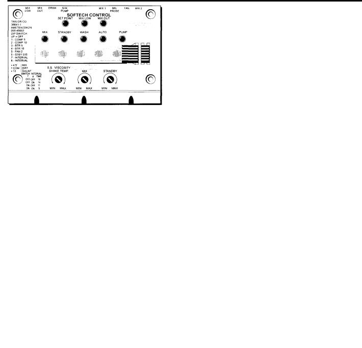
Self-Test Program
The Generation II controls are programmed for a self-test. The control can be used to help identify problems in the power board, the logic board, and the thermistor probes. The self-test program is not intended to, and will not take the place of a reasonable, and prudent service technician.
The self-test program is divided into two sections. The first section is an automatic function of the micro processor and the second section is performed by the technician.
The self-test program is initiated by holding down the MIX, WASH, AND PUMP keypads on the logic panel while simultaneously turning on the power switch. Hold down the keypads until all eight lights illuminate. If all eight lights do not illuminate, the control is defective. If the self-test cannot be initiated, the control is defective.
Figure 2.
Each light corresponds with a particular relay. The light on the panel will not extinguish until the test is completed for that particular relay.
Logic Panel Light |
Corresponding Relay |
MIX LOW |
Mix Relay |
MIX OUT |
Fan Relay |
MIX |
Pump Relay |
STANDBY |
Beater Motor Relay |
WASH |
Compressor Relay |
AUTO |
Spinner Relay |
PUMP |
Portion Relay |
In each of the tests the relay on the power board will close and the component will operate for three seconds. There is a ten second delay between each check.
When the self-test is initiated, all eight lights will remain on for three seconds. At this time, the processor will begin to check the power board relays as follows:
1.The SET POINT light turns off.
2.Ten seconds after the SET POINT light turns off, the mix relay closes for three seconds.
3.The mix relay opens and the MIX LOW light turns off.
4.Ten seconds later, the fan relay closes.
5.Three seconds later, the fan relay opens and the MIX OUT light turns off.
6.Ten seconds later, the pump relay closes.
7.Three seconds later, the pump relay opens and the mix light turns off.
8.Ten seconds later, the beater motor relay
closes.
9.Three seconds later, the beater motor relay opens and the STANDBY light turns off.
10.Ten seconds later, the compressor relay closes.
11.Three seconds later, the compressor relay
opens and the wash light turns off.
12.All lights are off and a tone sounds for three seconds. This designates the end of the first section.
If all or most of the power board relays fail to close, the logic panel is defective. If only one relay fails to close, the power board is defective. This test can be used to determine if a problem exists with the logic panel, the power board, or elsewhere in the freezer. In other words, if during the test the beater relay closes on the power board, but the beater motor contactor does not operate, the problem occurs after the command reaches the power board.
Self-Test - Part II
When the first section of the self-test is complete, the control will advance to the starting point of the second section. The technician will have to complete this portion of the test. The first part of this section verifies the function of the control potentiometers (adjustment screw).
During this test, the MIX, STANDBY, WASH, AUTO, and PUMP lights function in direct relationship with the "MIN" and "MAX" adjustments of the potentiometer. In other words, when the adjustment screw is turned all the way to "MIN", the MIX light will be lit. When the adjustment is turned all the way to "MAX", the PUMP light will be lit. If the screw adjustment is made between the "MAX" and the "MIN" adjustment, one of the other lights will illuminate depending on the adjustment.
These lights create a bar graph which is directly related to the product temperature. "MIX" is warm and "PUMP" is cold.
1.The SET POINT light is lit, indicating that the control is reading the soft serve viscosity potentiometer.
2.Rotate the adjustment screw back and forth from "MIN" to "MAX". The bar graph should travel accordingly. This indicates that the potentiometer is functional.
If the bar lights do not react, the logic panel is defective.
Important: If the freezer's controls have been set previously, return the adjustment to its original position. For example, if the WASH light was lit before an adjustment screw was rotated, before going to the next step, rotate the adjustment screw until the WASH light is lit again.
3.Press the MIX keypad once.
4.The MIX LOW light is lit, indicating that the control is reading the MIX potentiometer.
5.Rotate the adjustment screw as in Step 2,
6.Press the MIX keypad once.
7.The MIX OUT light is on, indicating the control is reading the STANDBY potentiometer.
8.Rotate the adjustment screw as in Step 2.
9.Press the MIX keypad once.
10.The MIX LOW light is lit, indicating that the control is reading the "MIX 1" terminal.
11.The capability of this terminal to read the thermistor probe can be checked by the following method:
a.Remove the thermistor probe wire from the "MIX 1" terminal.
b.Connect the "MIX 1" terminal directly to ground (simulating a warm probe). The MIX light will illuminate.
c.Remove the terminal connection from ground (simulating a cold probe). The PUMP light will illuminate.
If the lights do not react, the panel is defective.
12.Press the MIX keypad once.
13.The MIX OUT light is lit, indicating that the control is now reading the BARREL (freezing cylinder) probe terminal.
14.Check the freezing cylinder probe (as in
Step 13) by removing the wire from the panel.
15.Press the MIX keypad again, and the self-test program is terminated.
Control Overview

Pump Operation
The pump operates under the following conditions:
Pump Key
When the PUMP key is pressed, the pump is active by itself or with the WASH mode of operation.
ITEM |
DESCRIPTION |
PART NO. |
|
|
|
|
|
1 |
SCREW-1/4-20x 3/4 |
020128-2 |
|
2 |
MOTOR-REDUCER (50/60) |
036955-34 |
|
2A |
MOTOR |
049246-34 |
|
2B |
GEAR (50/60 HZ) |
049247-34 |
|
3 |
MOUNT-MOTOR |
036934 |
|
4 |
SLEEVE A.-MIX PUMPPH71, |
X45012 |
|
8751,8754 |
|||
|
|
Soft Serve Mix Pumps
The soft serve mix pump will be active for 30 seconds whenever the AUTO mode is entered. If a MIX OUT condition forces a side of the machine into the STANDBY mode of operation, the mix pump will not be active.
Mix Pump Draw Timer
During the AUTO mode, the mix pump will operate for 10 seconds after every draw of soft serve product.
ITEM |
DESCRIPTION |
PART NO. |
|
|
|
5 |
COUPLING-MOTOR-FLEXIBLE |
047936 |
6* |
SEAL-INPUT |
048836 |
7* |
SEAL-OUTPUT |
048837 |
8 |
NUT-PUMP SLEEVE |
036933 |
|
|
|
*NOT SHOWN
General Troubleshooting Guide
PROBLEM |
PROBABLE CAUSE |
REMEDY |
|
|
|
1. No product is being dispensed. |
Low on mix. The MIX OUT light is on. |
Add mix to the mix hopper |
|
The power switch is in the OFF |
Place the power switch to the ON |
|
position. |
position and press the AUTO keypad. |
|
Beater motor is out on reset. |
Allow the beater motor to cool. Place |
|
|
the power switch to the OFF position. |
|
|
Press the reset button firmly. Place the |
|
|
power switch to the ON position and |
|
|
press the WASH keypad. Open the |
|
|
side access panel and observe that |
|
|
the drive shaft is turning CLOCKWISE |
|
|
as viewed from the front of the unit. |
|
|
Press the AUTO keypad to return to |
|
|
the AUTO mode. |
|
Air/mix pump is incorrectly assembled |
Follow assembly procedures carefully. |
|
or improperly lubricated. |
|
|
Missing or incorrectly installed spring |
Replace or correctly install the spring |
|
and poppet in air/mix pump. |
and poppet on the mix inlet fitting. |
|
The mix pump ball crank is broken. |
Replace the component. |
|
The pump motor is not activated. |
Push the reset button. The draw valve |
|
|
must be fully raised to activate the |
|
|
pump motor. |
|
Incorrect usage of the mix feed tube |
Follow the correct feed tube |
|
(gravity style freezers). |
procedures and use of the air orifice. |
2. The product is too thick. |
Insufficient mix in the freezing cylinder. |
Check the air/mix pump assembly. |
|
|
The mix inlet tube must be fully |
|
|
submerged in mix. |
|
Improper priming procedures. |
Drain the freezing cylinder and |
|
|
re-prime the unit. |
|
The air/mix pump is incorrectly |
Follow assembly procedures carefully. |
|
assembled. |
|
|
The viscosity control is set too cold. |
Adjust the viscosity. |
PROBLEM |
PROBABLE CAUSE |
REMEDY |
|
|
|
|
|
3. The product is too soft. |
The draw rate is set too fast. |
Adjust the draw rate to 5 - 7-1/2 oz. |
|
|
|
(142 g. - 213 g.) of product by weight |
|
|
|
every 10 seconds. |
|
|
Outdrawing the capacity of the |
The continuous draw rate is |
|
|
freezing cylinder. |
approximately 15 cones. |
|
|
There is inadequate air space around |
A minimum of 3 " (7.6 cm.) of |
|
|
the unit. |
clearance around all sides is required. |
|
|
|
Exception: The minimum requirement |
|
|
|
for the 338 and 750 is 6" (15.2 cm.). |
|
|
Dirty condenser or air filters on air |
Clean regularly. |
|
|
cooled units. |
|
|
|
Inadequate water supply on water |
Check the water supply. Check the |
|
|
cooled units. |
water lines for leaks or kinks. |
|
|
Bad scraper blades. |
Replace the scraper blades. |
|
|
The viscosity control is set too warm. |
Adjust the viscosity. |
|
|
Incorrect usage of the mix feed tube |
Follow the correct feed tube |
|
|
(gravity style freezers). |
procedures and use of the air orifice. |
|
4. The mix in the hopper is too |
The hopper cover is not in position. |
Clean the hopper cover and place it in |
|
warm. |
|
position. |
|
|
The hopper temperature is out of |
Adjust the temperature control. |
|
|
adjustment. |
|
|
5. The mix in the hopper is too cold. |
The hopper temperature is out of |
Adjust the temperature control. |
|
|
adjustment. |
|
|
6. Product is collecting on top of the |
The top o-ring on the draw valve is |
Lubricate properly or replace the |
|
freezer door. |
improperly lubricated or worn. |
o-ring. |
|
7. Excessive mix leakage from the |
The bottom o-ring on the draw valve is |
Lubricate properly or replace the |
|
bottom of the door spout. |
improperly lubricated or worn. |
o-ring. |
|
8. Excessive mix leakage into the |
The seal on the drive shaft is |
Lubricate properly or replace the seal. |
|
long drip pan. |
improperly lubricated or worn. |
|
|
|
The seal is installed inside-out on the |
Install the seal correctly. |
|
|
drive shaft. |
|
|
9. Excessive mix leakage from the |
Worn or missing o-rings on the pump |
Install or replace the o-rings. |
|
rear of the freezer into the short |
drive shaft. |
|
|
drip pans. |
|
|
|
Inadequate lubrication of the drive |
Lubricate properly. |
||
|
|||
|
shaft. |
|
|
|
The drive shaft and beater assembly |
Verify the refrigerant charge and |
|
|
work forward. |
check for a shorted freezing cylinder. |
|
|
Worn rear shell bearing. |
Replace the component. |
|
|
Gear box out of alignment. |
Re-align the gear box. |
|
10. The drive shaft is stuck in the |
Mix and lubricant have collected in the |
Brush clean the rear shell bearing |
|
drive coupling. |
drive coupling. |
area regularly. |
|
|
Rounded corners of the drive shaft, |
Replace worn component(s). |
|
|
the drive coupling or both. |
|
|
|
The gear box is out of alignment. |
Re-align the gear box. |
PROBLEM |
PROBABLE CAUSE |
REMEDY |
|
|
|
11. Freezing cylinder walls are |
Missing or worn front bearing. |
Install or replace the front bearing. |
scored. |
Broken beater pins (pump style |
Replace the beater assembly. When |
|
freezers, only). |
installing scraper blades, be sure they |
|
|
are properly attached over the pins. |
|
The beater assembly is bent. |
The beater assembly must be |
|
|
replaced. |
|
The gear box is out of alignment. |
Re-align the gear box. |
12. The pump will not operate in the |
The pump motor is not activated. |
Push the reset button. |
PUMP mode. |
The membrane switch is defective. |
Replace the switch. |
13. The unit will not run when in the |
The unit is unplugged. |
Plug into wall receptacle. |
AUTO mode. |
The beater motor is out on reset. |
Allow the beater motor to cool. Place |
|
|
the power switch to the OFF position. |
|
|
Press the reset button firmly. Place the |
|
|
power switch to the ON position, and |
|
|
press the WASH keypad. Open the |
|
|
side access panel and observe that |
|
|
the drive shaft is turning clockwise as |
|
|
viewed from the front of the unit. Press |
|
|
the AUTO keypad to return to the |
|
|
AUTO mode. |
|
|
Note: Do not use metal objects to |
|
|
press the reset button. |
|
The circuit breaker is off, or the fuse is |
Turn the breaker on, or replace the |
|
blown. |
fuse. |
|
Low on mix. The MIX OUT light is on. |
Add mix to the mix hopper and press |
|
|
the AUTO keypad. |
|
The water is turned off, on water |
Turn the water on. |
|
cooled units. |
|
14. Product is not feeding into the |
The mix inlet hole is frozen up. |
The hopper temperature needs |
freezing cylinder. |
|
adjustment. |
|
Incorrect usage of the mix feed tube |
Follow the correct feed tube |
|
(gravity style freezers). |
procedures and use of the air orifice. |
15. Product is "popping" when drawn. |
The draw rate is set too fast. |
The draw rate should be set at 5 - |
|
|
7-1/2 oz. of product per 10 seconds. |
|
The pump is assembled incorrectly. |
Assemble and lubricate according to |
|
|
instructions in the Operator's manual. |
16. The MIX LOW and MIX OUT |
There is milkstone build-up in the |
Clean the hoppers thoroughly. |
probes are not functioning. |
hopper. |
|
Troubleshooting Pump Style Freezers
PROBLEM |
PROBABLE CAUSE |
REMEDY |
|
|
|
1. The air/mix pump will not operate |
The circuit breaker is off. |
Check the breaker. |
when the PUMP keypad is |
|
|
pressed. |
The power cord is unplugged. |
Plug in the power cord. |
|
The freezer is out on reset. |
Reset the freezer. |
|
The pump motor is out on reset. |
Press the PUMP keypad to cancel the |
|
|
pump operation. Press the reset |
|
|
button on the side of the pump motor |
|
|
reducer. Press the PUMP keypad to |
|
|
continue pump operation. |
2. The air/mix pump will not operate |
The pump motor is out on reset. |
Press the PUMP keypad to cancel the |
when the draw valve is opened |
|
pump operation. Press the reset |
and the unit is in the AUTO mode. |
|
button on the side of the pump motor |
|
|
reducer. Press the PUMP keypad to |
|
|
continue pump operation. |
|
The pump motor relay is |
Replace the relay. |
|
malfunctioning. |
|
3. The piston travels back and forth, |
Inspect the check bands. |
The check bands must be installed |
but product is not being pumped. |
|
correctly, fit tightly, and not have any |
|
|
holes or lubrication. |
|
Inspect the o-rings. |
O-rings must not be worn, torn, or fit |
|
|
too loosely. |
|
Check the pump cylinder. |
The piston and liquid valve body must |
|
|
be assembled correctly, and fit snugly |
|
|
in the pump cylinder. |
|
The spring or poppet is missing or |
Replace. |
|
defective. |
|
4. Excessive pump cylinder wear. |
Inadequate or incorrect lubrication of |
Follow lubrication procedures |
|
pump cylinder. |
carefully. |
|
Incorrect ball crank rotation. (Must be |
Reverse pump rotation. |
|
counterclockwise). |
|
5. Pitting occurring inside the pump |
Cleaner was left inside the pump |
After brush cleaning the pump |
cylinder. |
cylinder. |
cylinder, allow it to dry. Follow |
|
|
disassembly procedures carefully. |
6. The ball crank of the motor |
Incorrect rotation of pump motor. |
Reverse pump rotation. |
reducer is broken. |
|
|
7. Too much pressure is in the |
Plugged relief hole in the liquid valve |
Clean. |
freezing cylinder. |
body below the poppet. |
|
8. Not enough pressure is in the |
The spring in the liquid valve body is |
Replace. |
freezing cylinder. |
weak or bent. |
|
|
The draw switch is malfunctioning. |
Replace the draw switch. |
|
The poppet is missing. |
Install the poppet. |

Electrical Troubleshooting
The following information provides a sequential list of electrical components that L-1 power travels through to initiate various operations.
Auto Mode of Operation:
L-1 power travels through the power switch, beater overload switch, the compressor high pressure cut-out switch, the overload terminal (OL) on the power board, the BTR terminal of the power board, and energizes the coil of the beater motor contactor.
L-1 power travels through the power switch, beater overload switch, the compressor high pressure cut-out switch, the overload terminal (OL) on the power board, the COM terminal of the power board, and energizes the coil of the compressor contactor.
L-1 power travels through the power switch, beater overload switch, the compressor high pressure cut-out switch, the L-1 terminal of the power board, the MIX terminal of the power board, and energizes the hopper refrigeration compressor and condenser fan.
Wash Mode of Operation:
L-1 power travels through the power switch, beater overload switch, the compressor high pressure cut-out switch, the overload terminal (OL) on the power board, the BTR terminal of the power board, and energizes the coil of the beater motor contactor.
Pump Mode of Operation:
L-1 power travels through the power switch, beater overload switch, the compressor high pressure cut-out switch, the overload terminal (OL) on the power board, the PUMP terminal of the power board, and energizes the coil of the pump motor.

Warranty Explanation
Class 103 Parts: |
The warranty for new equipment parts is one year from the original date of unit |
|
installation, with a replacement parts warranty of three months. |
Class 212 Parts: |
The warranty for new equipment parts is two years from the original date of unit |
|
installation, with a replacement parts warranty of twelve months. |
Class 512 Parts: |
The warranty for new equipment parts is five years from the original date of unit |
|
installation, with a replacement parts warranty of twelve months.. |
Class 000 Parts: |
Wear Items - no warranty. |
CAUTION: Warranty is valid only if required service work is provided by an Authorized Taylor Service Technician.
 Loading...