


Model PH90
Combination Freezer
Operating Instructions
047772-M
2/00

Complete this page for quick reference when service is required:
Taylor Distributor:
Address:
Phone:
Service:
Parts:
Date of Installation:
Information found on data plate:
Model Number:
Serial Number:
Electrical Specs: Voltage |
|
Cycle |
||||||
|
Phase |
|
|
|
|
|
||
Maximum Fuse Size: |
|
|
|
|
Amps |
|||
Minimum Wire Ampacity: |
|
|
|
|
Amps |
|||
Part Number: |
|
|
|
|
|
|||
E February, 2000 Taylor All rights reserved. 047772-M
The word Taylor and the Crown design
are registered trademarks in the United States of America and certain other countries.
Taylor Company
a division of Carrier Commercial Refrigeration, Inc. 750 N. Blackhawk Blvd.
Rockton, IL 61072

|
|
Table of Contents |
Section 1 |
To the Installer . . . . . . . . . . . . . . . . |
. . . . . . . . . . . . . . . . . . . . . . . . . . . . 1 |
Installer Safety . . . . . . . . . . . . . . . . . . . . . . . . . . . . |
. . . . . . . . . . . . . . . . . . . . . . . . . . . . 1 |
|
Site Preparation . . . . . . . . . . . . . . . . . . . . . . . . . . . |
. . . . . . . . . . . . . . . . . . . . . . . . . . . . 1 |
|
Air Cooled Units . . . . . . . . . . . . . . . . . . . . . . . . . . . |
. . . . . . . . . . . . . . . . . . . . . . . . . . . . 2 |
|
Water Connections (Water Cooled Units Only) |
. . . . . . . . . . . . . . . . . . . . . . . . . . . . 2 |
|
Electrical Connections . . . . . . . . . . . . . . . . . . . . . |
. . . . . . . . . . . . . . . . . . . . . . . . . . . . 2 |
|
Beater Rotation . . . . . . . . . . . . . . . . . . . . . . . . . . . |
. . . . . . . . . . . . . . . . . . . . . . . . . . . . 3 |
|
Refrigerant |
. . . . . . . . . . . . . . . . . . . . . . . . . . . . . . . |
. . . . . . . . . . . . . . . . . . . . . . . . . . . . 3 |
Section 2 |
To the Operator . . . . . . . . . . . . . . . |
. . . . . . . . . . . . . . . . . . . . . . . . . . . . 4 |
Section 3 |
Safety . . . . . . . . . . . . . . . . . . . . . . . . |
. . . . . . . . . . . . . . . . . . . . . . . . . . . . 5 |
Section 4 |
Operator Parts Identification . . . |
. . . . . . . . . . . . . . . . . . . . . . . . . . . . 7 |
Section 5 |
Important: To the Operator . . . . . |
. . . . . . . . . . . . . . . . . . . . . . . . . . . . 15 |
Symbol Definitions . . . . . . . . . . . . . . . . . . . . . . . . |
. . . . . . . . . . . . . . . . . . . . . . . . . . . . 15 |
|
Power Switch . . . . . . . . . . . . . . . . . . . . . . . . . . . . . |
. . . . . . . . . . . . . . . . . . . . . . . . . . . . 16 |
|
Indicator Lights . . . . . . . . . . . . . . . . . . . . . . . . . . . |
. . . . . . . . . . . . . . . . . . . . . . . . . . . . 16 |
|
Flavor Selector Keypad . . . . . . . . . . . . . . . . . . . . |
. . . . . . . . . . . . . . . . . . . . . . . . . . . . 16 |
|
Liquid Crystal Display . . . . . . . . . . . . . . . . . . . . . . |
. . . . . . . . . . . . . . . . . . . . . . . . . . . . 16 |
|
Heater Switch . . . . . . . . . . . . . . . . . . . . . . . . . . . . . |
. . . . . . . . . . . . . . . . . . . . . . . . . . . . 16 |
|
Reset Mechanism . . . . . . . . . . . . . . . . . . . . . . . . . |
. . . . . . . . . . . . . . . . . . . . . . . . . . . . 16 |
|
Adjustable Draw Handle . . . . . . . . . . . . . . . . . . . |
. . . . . . . . . . . . . . . . . . . . . . . . . . . . 17 |
|
Operating Screen Descriptions . . . . . . . . . . . . . . |
. . . . . . . . . . . . . . . . . . . . . . . . . . . . 17 |
|
Operator Menu . . . . . . . . . . . . . . . . . . . . . . . . . . . |
. . . . . . . . . . . . . . . . . . . . . . . . . . . . 20 |
|
Section 6 |
Operating Procedures . . . . . . . . . |
. . . . . . . . . . . . . . . . . . . . . . . . . . . . 23 |
Equipment Set Up . . . . . . . . . . . . . . . . . . . . . . . . . |
. . . . . . . . . . . . . . . . . . . . . . . . . . . . 23 |
|
Freezing Cylinder Assembly -- Shake Side . . . . |
. . . . . . . . . . . . . . . . . . . . . . . . . . . . 23 |
|
Freezing Cylinder Assembly -- Soft Serve Side |
. . . . . . . . . . . . . . . . . . . . . . . . . . . . 27 |
|
Mix Hopper Assembly . . . . . . . . . . . . . . . . . . . . . |
. . . . . . . . . . . . . . . . . . . . . . . . . . . . 31 |
|
Sanitizing -- Shake Side . . . . . . . . . . . . . . . . . . . . |
. . . . . . . . . . . . . . . . . . . . . . . . . . . . 35 |
|
Sanitizing -- Soft Serve Side . . . . . . . . . . . . . . . . |
. . . . . . . . . . . . . . . . . . . . . . . . . . . . 37 |
|
Priming -- Shake Side . . . . . . . . . . . . . . . . . . . . . . |
. . . . . . . . . . . . . . . . . . . . . . . . . . . . 39 |
|
Priming -- Soft Serve Side . . . . . . . . . . . . . . . . . . |
. . . . . . . . . . . . . . . . . . . . . . . . . . . . 40 |
|
Daily Closing Procedures . . . . . . . . . . . . . . . . . . |
. . . . . . . . . . . . . . . . . . . . . . . . . . . . 40 |
|
Daily Opening Procedures . . . . . . . . . . . . . . . . . . |
. . . . . . . . . . . . . . . . . . . . . . . . . . . . 44 |
|
Syrup System . . . . . . . . . . . . . . . . . . . . . . . . . . . . . |
. . . . . . . . . . . . . . . . . . . . . . . . . . . . 47 |
|
Syrup Pump . . . . . . . . . . . . . . . . . . . . . . . . . . . . . . |
. . . . . . . . . . . . . . . . . . . . . . . . . . . . 50 |
|
Model PH90 |
Table of Contents |
|
|

Table of Contents - Page 2
Manual Brush Cleaning . . . . . . . . . . . . . . . . . . . . . . . . . . . . . . . . . . . . . . . . . . . . . . . . 55
Draining Product From The Freezing Cylinder . . . . . . . . . . . . . . . . . . . . . . . . . . . . 55
Rinsing . . . . . . . . . . . . . . . . . . . . . . . . . . . . . . . . . . . . . . . . . . . . . . . . . . . . . . . . . . . . . . 56
Cleaning and Sanitizing . . . . . . . . . . . . . . . . . . . . . . . . . . . . . . . . . . . . . . . . . . . . . . . . 57
Disassembly -- Shake Side . . . . . . . . . . . . . . . . . . . . . . . . . . . . . . . . . . . . . . . . . . . . . 57
Disassembly -- Soft Serve Side . . . . . . . . . . . . . . . . . . . . . . . . . . . . . . . . . . . . . . . . . 58
Brush Cleaning . . . . . . . . . . . . . . . . . . . . . . . . . . . . . . . . . . . . . . . . . . . . . . . . . . . . . . . 59
Sanitizing the Syrup System . . . . . . . . . . . . . . . . . . . . . . . . . . . . . . . . . . . . . . . . . . . . 60
Section 7 Important: Operator Checklist . . . . . . . . . . . . . . . . . . . . . . . . . . . . . . 61
During Cleaning and Sanitizing . . . . . . . . . . . . . . . . . . . . . . . . . . . . . . . . . . . . . . . . . 61
Troubleshooting Bacterial Count . . . . . . . . . . . . . . . . . . . . . . . . . . . . . . . . . . . . . . . . 61
Regular Maintenance Checks . . . . . . . . . . . . . . . . . . . . . . . . . . . . . . . . . . . . . . . . . . . 61
Winter Storage . . . . . . . . . . . . . . . . . . . . . . . . . . . . . . . . . . . . . . . . . . . . . . . . . . . . . . . . 62
Section 8 Troubleshooting Guide . . . . . . . . . . . . . . . . . . . . . . . . . . . . . . . . . . . . 63
Section 9 Parts Replacement Schedule . . . . . . . . . . . . . . . . . . . . . . . . . . . . . . . 75
Section 10 Parts List . . . . . . . . . . . . . . . . . . . . . . . . . . . . . . . . . . . . . . . . . . . . . . . . . 76
Wiring Diagrams . . . . . . . . . . . . . . . . . . . . . . . . . . . . . . . . . . . . . . . . . . . . . . . . . . . . . . 96
Note: Continuing research results in steady improvements; therefore, information in this manual is subject to change without notice.
E February, 2000 Taylor All rights reserved. 047772-M
The word Taylor and the Crown design
are registered trademarks in the United States of America and certain other countries.
Taylor Company
a division of Carrier Commercial Refrigerati 750 N. Blackhawk Blvd.
Rockton, IL 61072
Table of Contents |
Model PH90 |
|
|

Section 1 |
To the Installer |
|
|
The following are general installation instructions. For complete installation details, please see the check out card.
Installer Safety
 In all areas of the world, equipment should be installed in accordance with existing local codes. Please contact your local authorities if you have any questions.
Care should be taken to ensure that all basic safety practices are followed during the installation and servicing activities related to the installation and service of Taylor equipment.
SOnly authorized Taylor service personnel should perform installation and repairs on the equipment.
SAuthorized service personnel should consult OSHA Standard 29CFRI910.147 or the applicable code of the local area for the industry standards on lockout/tagout procedures before beginning any installation or repairs.
SAuthorized service personnel must ensure that the proper PPE is available and worn when required during installation and service.
SAuthorized service personnel must remove all metal jewelry, rings, and watches before working on electrical equipment.
 The main power supply(s) to the freezer must be disconnected prior to performing any repairs. Failure to follow this instruction may result in personal injury or death from electrical shock or hazardous moving parts as well as poor performance or damage to the equipment.
Note: All repairs must be performed by an authorized Taylor Service Technician.
 This unit has many sharp edges that can cause severe injuries.
Site Preparation
Review the area the unit is to be installed in before uncrating the unit, making sure that all possible hazards the user or equipment may come into have been addressed.
For Indoor Use Only: This unit is designed to operate indoors, under normal ambient temperatures of 70_-75_F (21_-24_C). The freezer has successfully performed in high ambient temperatures of 104_(40_C) at reduced capacities.
 This unit must NOT be installed in an area where a water jet or hose can be used. NEVER use a water jet or hose to rinse or clean the unit. Failure to follow this instruction may result in electrocution.
 This unit must be installed on a level surface to avoid the hazard of tipping. Extreme care should be taken in moving this equipment for any reason. Two or more persons are required to safely move this unit. Failure to comply may result in personal injury or equipment damage.
Uncrate the unit and inspect it for damage. Report any damage to your Taylor Distributor.
This piece of equipment is made in the USA and has USA sizes of hardware. All metric conversions are approximate and vary in size.
This machine is designed for indoor use only.
DO NOT install the machine in an area where |
a water jet could be used. Failure to follow this instruction may result in serious electrical shock.
081210
Model PH90 |
1 |
To the Installer |
|
|
|

Air Cooled Units
DO NOT obstruct air intake and discharge openings:
Air cooled units require a minimum of 3” (76 mm) of clearance around all sides of the freezer to allow for adequate air flow across the condensers. Install the deflector provided to prevent recirculation of warm air. Failure to allow adequate clearance can reduce the refrigeration capacity of the freezer and possibly cause permanent damage to the compressors.
Water Connections
(Water Cooled Units Only)
An adequate cold water supply must be provided with a hand shut--off valve. On the rear of the unit, two 1/2” I.P.S. water connections for inlet and outlet have been provided for easy hook--up. 1/2” inside diameter water lines should be connected to the machine. (Flexible lines are recommended, if local codes permit.) Depending on local water conditions, it may be advisable to install a water strainer to prevent foreign substances from clogging the automatic water valve. There will be only one water “in” and one water “out” connection. DO NOT install a hand shut--off valve on the water “out” line! Water should always flow in this order: first, through the automatic water valve; second, through the condenser; and third, through the outlet fitting to an open trap drain.
 A back flow prevention device is required on the incoming water connection side. Please refer to the applicable National, State, and local codes for determining the proper configuration.
Electrical Connections
In the United States, this equipment is intended to be installed in accordance with the National Electrical Code (NEC), ANSI/NFPA 70-1987. The purpose of the NEC code is the practical safeguarding of persons and property from hazards arising from the use of electricity. This code contains provisions considered necessary for safety. In all other areas of the world, equipment should be installed in accordance with the existing local codes. Please contact your local authorities.
081210
FOLLOW YOUR LOCAL ELECTRICAL CODES!
Each unit requires one power supply for each data label on the unit. Check the data label on the freezer for fuse, circuit ampacity and other electrical specifications. Refer to the wiring diagram provided inside of the electrical box, for proper power connections.
 CAUTION: THIS EQUIPMENT MUST BE PROPERLY GROUNDED! FAILURE TO DO SO CAN RESULT IN SEVERE PERSONAL INJURY FROM ELECTRICAL SHOCK!
 This unit is provided with an equipotential grounding lug that is to be properly attached to the rear of the frame by the authorized installer. The installation location is marked by the equipotential bonding symbol (5021 of IEC 60417-1) on both the removable panel and the equipment’s frame.
SStationary appliances which are not equipped with a power cord and a plug or another device to disconnect the appliance from the power source must have an all-pole disconnecting device with a contact gap of at least 3mm installed in the external installation.
SAppliances that are permanently connected to fixed wiring and for which leakage currents may exceed 10 mA, particularly when disconnected, not used for long periods, or during initial installation, shall have protective devices such as a GFI to protect against the leakage of current, installed by authorized personnel to the local codes.
SSupply cords used with this unit shall be oil-resistant, sheathed flexible cable, not lighter than ordinary polychloroprene or other equivalent synthetic elastomer-sheathed cord (Code designation 60245 IEC 57) installed with the proper cord anchorage to relieve conductors from strain, including twisting, at the terminals and protect the insulation of the conductors from abrasion.
To the Installer |
2 |
Model PH90 |
|
|
|

Beater Rotation
 Beater rotation must be clockwise as viewed looking into the freezing cylinder.
Note: The following procedures must be performed by an authorized Taylor service technician.
To correct rotation on a three--phase unit, interchange any two incoming power supply lines at freezer main terminal block only.
To correct rotation on a single--phase unit, change the leads inside the beater motor. (Follow diagram printed on motor.)
Electrical connections are made directly to the terminal block. The terminal block is provided in the main control box located behind the panel in the rear of the syrup compartment.
Refrigerant
 In consideration of our environment, Taylor proudly uses only earth friendly HFC refrigerants. The HFC refrigerant used in this unit is R404A. This refrigerant is generally considered non-toxic and non-flammable, with an Ozone Depleting Potential (ODP) of zero (0).
However, any gas under pressure is potentially hazardous and must be handled with caution.
NEVER fill any refrigerant cylinder completely with liquid. Filling the cylinder to approximately 80% will allow for normal expansion.
 Refrigerant liquid sprayed onto the skin may cause serious damage to tissue. Keep eyes and skin protected. If refrigerant burns should occur, flush immediately with cold water. If burns are severe, apply ice packs and contact a physician immediately.
 Taylor reminds technicians to be cautious of government laws regarding refrigerant recovery, recycling, and reclaiming systems. If you have any questions regarding these laws, please contact the factory Service Department.
 WARNING: R404A refrigerant used in conjunction with polyolester oils is extremely moisture absorbent. When opening a refrigeration system, the maximum time the system is open must not exceed 15 minutes. Cap all open tubing to prevent humid air or water from being absorbed by the oil.
081210
Model PH90 |
3 |
To the Installer |
|
|
|

Section 2 |
To the Operator |
|
|
The freezer you have purchased has been carefully engineered and manufactured to give you dependable operation. The Taylor Model PH90, when properly operated and cared for, will produce a consistent quality product. Like all mechanical products, this machine will require cleaning and maintenance. A minimum amount of care and attention is necessary if the operating procedures outlined in this manual are followed closely.
This Operator’s Manual should be read before operating or performing any maintenance on your equipment.
Your Model PH90 will NOT eventually compensate and correct for any errors during the set--up or filling operations. Thus, the initial assembly and priming procedures are of extreme importance. It is strongly recommended that personnel responsible for the equipment’s operation, both assembly and disassembly, study these procedures in order to be properly trained and to make sure that no misunderstandings exist.
In the event you should require technical assistance, please contact your local authorized Taylor Distributor.
Note: Warranty is valid only if the parts are authorized Taylor parts, purchased from an authorized Taylor Distributor, and the required service work is provided by an authorized Taylor service technician. Taylor reserves the right to deny warranty claims on equipment or parts if non--approved parts or refrigerant were installed in the machine, system modifications were performed beyond factory recommendations, or it is determined that the failure was caused by neglect or abuse.
Note: Constant research results in steady improvements; therefore, information in this manual is subject to change without notice.
 If the crossed out wheeled bin symbol is affixed to this product, it signifies that this product is compliant with the EU Directive as well as other similar legislation in effect after August 13, 2005. Therefore, it must be collected separately after its use is completed, and cannot be disposed as unsorted municipal waste.
081210
The user is responsible for returning the product to the appropriate collection facility, as specified by your local code.
For additional information regarding applicable local laws, please contact the municipal facility and/or local distributor.
Compressor Warranty Disclaimer
The refrigeration compressor(s) on this machine are warranted for the term indicated on the warranty card accompanying this machine. However, due to the Montreal Protocol and the U.S. Clean Air Act Amendments of 1990, many new refrigerants are being tested and developed, thus seeking their way into the service industry. Some of these new refrigerants are being advertised as drop--in replacements for numerous applications. It should be noted that, in the event of ordinary service to this machine’s refrigeration system, only the refrigerant specified on the affixed data label should be used. The unauthorized use of alternate refrigerants will void your compressor warranty. It will be the owner’s responsibility to make this fact known to any technician he employs.
It should also be noted that Taylor does not warrant the refrigerant used in its equipment. For example, if the refrigerant is lost during the course of ordinary service to this machine, Taylor has no obligation to either supply or provide its replacement either at billable or unbillable terms. Taylor does have the obligation to recommend a suitable replacement if the original refrigerant is banned, obsoleted, or no longer available during the five year warranty of the compressor.
The Taylor Company will continue to monitor the industry and test new alternates as they are being developed. Should a new alternate prove, through our testing, that it would be accepted as a drop--in replacement, then the above disclaimer would become null and void. To find out the current status of an alternate refrigerant as it relates to your compressor warranty, call the local Taylor Distributor or the Taylor Factory. Be prepared to provide the Model/Serial Number of the unit in question.
To the Operator |
4 |
Model PH90 |
|
|
|

Section 3 |
Safety |
|
|
We at Taylor Company are concerned about the safety of the operator when he or she comes in contact with the freezer and its parts. Taylor has gone to extreme efforts to design and manufacture built--in safety features to protect both you and the service technician. As an example, warning labels have been attached to the freezer to further point out safety precautions to the operator.
 IMPORTANT -- Failure to adhere to the following safety precautions may result in severe personal injury or death. Failure to comply with these warnings may damage the machine and its components. Component damage will result in part replacement expense and service repair expense.
 DO NOT operate the freezer without reading this Operator Manual. Failure to follow this instruction may result in equipment damage, poor freezer performance, health hazards, or personal injury.
 This unit is provided with an equipotential grounding lug that is to be properly attached to the rear of the frame by the authorized installer. The installation location is marked by the equipotential bonding symbol (5021 of IEC 60417-1) on both the removable panel and the equipment’s frame.
 DO NOT use a water jet to clean or rinse the freezer. Failure to follow these instructions may result in serious electrical shock.
SDO NOT operate the freezer unless it is properly grounded.
SDO NOT operate the freezer with larger fuses than specified on the freezer data label.
SDO NOT attempt any repairs unless the main power supply to the freezer has been disconnected. Contact your local authorized Taylor Distributor for service.
SStationary appliances which are not equipped with a power cord and a plug or another device to disconnect the appliance from the power source must have an all-pole disconnecting device with a contact gap of at least 3mm installed in the external installation.
SAppliances that are permanently connected to fixed wiring and for which leakage currents may exceed 10 mA, particularly when disconnected, not used for long periods, or during initial installation, shall have protective devices such as a GFI to protect against the leakage of current, installed by authorized personnel to the local codes.
SSupply cords used with this unit shall be oil-resistant, sheathed flexible cable, not lighter than ordinary polychloroprene or other equivalent synthetic elastomer-sheathed cord (Code designation 60245 IEC 57) installed with the proper cord anchorage to relieve conductors from strain, including twisting, at the terminals and protect the insulation of the conductors from abrasion.
Failure to follow these instructions may result in electrocution. Contact your local authorized Taylor Distributor for service.
081210
Model PH90 |
5 |
Safety |
|
|
|

SDO NOT allow untrained personnel to operate this machine.
SDO NOT operate the freezer unless all service panels and access doors are restrained with screws.
SDO NOT remove any internal operating parts (examples: freezer door, beater, scraper blades, etc.) unless all control switches are in the OFF position.
Failure to follow these instructions may result in severe personal injury to fingers or hands from hazardous moving parts.
 This unit has many sharp edges that can cause severe injuries.
SDO NOT put objects or fingers in the door spout. This may contaminate the product and cause severe personal injury from blade contact.
SUSE EXTREME CAUTION when removing the beater asssembly. The scraper blades are very sharp.
SCAUTION--SHARP EDGES: Two people are required to handle the cup/cone dispenser. Protective gloves must be worn and the mounting holes must NOT be used to lift or hold the dispenser. Failure to follow this instruction can result in personal injury to fingers or equipment damage.
 DO NOT draw product during the HEAT cycle because of high product temperatures.
081210
 This freezer must be placed on a level surface. Failure to comply may result in personal injury or equipment damage.
 Cleaning and sanitizing schedules are governed by your state or local regulatory agencies and must be followed accordingly. Please refer to the cleaning section of this manual for the proper procedure to clean this unit.
DO NOT obstruct air intake and discharge openings:
Air cooled units require a minimum of 3” (76 mm) minimum air space all sides. Install the deflector provided to prevent recirculation of warm air. Failure to follow this instruction may cause poor freezer performance and damage to the machine.
For Indoor Use Only: This unit is designed to operate indoors, under normal ambient temperatures of 70_ - 75_F (21_ - 24_C). The freezer has successfully performed in high ambient temperatures of 104_(40_C) at reduced capacities.
NOISE LEVEL: Airborne noise emission does not exceed 78 dB(A) when measured at a distance of 1.0 meter from the surface of the machine and at a height of 1.6 meters from the floor.
Safety |
6 |
Model PH90 |
|
|
|

Section 4 Operator Parts Identification
|
|
|
|
|
|
|
|
|
|
|
|
|
|
|
|
|
|
|
|
|
|
|
|
|
|
|
|
|
|
|
|
|
|
|
|
|
|
|
|
|
|
|
|
|
|
|
|
|
|
|
|
|
|
|
|
|
|
|
|
|
|
|
|
|
|
|
|
|
|
|
|
|
|
|
|
|
|
|
|
|
|
|
|
|
|
|
|
|
|
|
|
|
|
|
|
|
|
|
|
|
|
|
|
|
|
|
|
|
|
|
|
|
|
|
|
|
|
|
|
|
|
|
|
|
|
|
|
|
|
|
|
|
|
|
|
|
|
|
|
|
|
|
|
|
|
|
|
|
|
|
|
|
|
|
|
|
|
|
|
|
|
|
|
|
|
|
|
|
|
|
|
|
|
|
|
|
|
|
|
|
|
|
|
|
|
|
|
|
|
|
|
|
|
|
|
|
|
|
|
|
|
|
|
|
|
|
|
|
|
|
|
|
|
|
|
|
|
|
|
|
|
|
|
|
|
|
|
|
|
|
|
|
|
|
|
|
|
|
|
|
|
|
|
|
|
|
|
|
|
|
|
|
|
|
|
|
|
|
|
|
|
|
|
|
|
|
|
|
|
|
|
|
|
|
|
|
|
|
|
|
|
|
|
|
|
|
|
|
|
|
|
|
|
|
|
|
|
|
|
|
|
|
|
|
|
|
|
|
|
|
|
|
|
|
|
|
|
|
|
|
|
|
|
|
|
|
|
|
|
|
|
|
|
|
|
|
|
|
|
|
|
|
|
|
|
|
|
|
|
|
|
|
|
|
|
|
|
|
|
|
|
|
|
|
|
|
|
|
|
|
|
|
|
|
|
|
|
|
|
|
|
|
|
|
|
|
|
|
|
|
|
|
|
|
|
|
|
|
|
|
|
|
|
|
|
|
|
|
|
|
|
|
|
|
|
|
|
|
|
|
|
|
|
|
|
|
|
|
|
|
|
|
|
|
|
|
|
|
|
|
|
|
|
|
|
|
|
|
|
|
|
|
|
|
|
|
|
|
|
|
|
Model PH90 |
7 |
Operator Parts Identification |
|||||||||||||||||||
|
|
|
|
|
|
|
|
|
|
|
|
|
|
|
|
|
|
|
|
|
|

PH90 Exploded View Parts Identification
ITEM |
DESCRIPTION |
PART NO. |
|
|
|
1 |
COVER A.-HOPPER |
X42628-SER |
|
|
|
1a |
KNOB-MIX COVER |
025429 |
|
|
|
1b |
RETAINER-HOPPER COVER |
042619 |
|
|
|
1c |
SCREW-8-32 X 1/2 OVAL HD |
043295 |
|
|
|
2 |
AGITATOR |
X44797 |
|
|
|
3 |
PAN-DRIP HEAT TREAT |
048204 |
|
|
|
4 |
PANEL-REAR |
048208 |
|
|
|
5 |
LOUVER-SIDE-RIGHT |
013631 |
|
|
|
6 |
PANEL-UPPER SIDE RIGHT |
051632 |
|
|
|
7 |
TRIM-REAR CORNER RIGHT |
044053 |
|
|
|
8 |
PANEL A.-SIDE LOWER R |
X46450-SER |
|
|
|
9 |
PIN-RETAINING-HOPPER |
043934 |
|
CVR |
|
10 |
CASTER-SWV-3/4-10 ST. 4IN |
044106 |
|
|
|
11 |
SCREW-1/4-20X3/8 RHM-SS |
011694 |
|
|
|
12 |
TRAY-DRIP |
028542 |
|
|
|
13 |
SHIELD-SPLASH |
028548 |
|
|
|
14 |
DISPLAY-LIQUID CRYSTAL |
X38062-SER |
|
|
|
15 |
DECAL-DEC-TAYLOR |
052282 |
|
|
|
ITEM |
DESCRIPTION |
PART NO. |
|
|
|
16 |
PANEL A.-FRONT |
X51576 |
|
|
|
17 |
HOLDER-CUP-SHAKE 3.906” |
046939 |
|
|
|
18 |
PAN-DRIP 19-1/2 LONG |
035034 |
|
|
|
19 |
JAR-SYRUP PLASTIC |
036573 |
|
|
|
20 |
JAR-SYRUP STAINLESS |
036574 |
|
|
|
21 |
LID-SYRUP JAR |
042706 |
|
|
|
22 |
LOUVER-SIDE-LEFT |
028288 |
|
|
|
23 |
PANEL SIDE UPPER LEFT |
051631 |
|
|
|
24 |
PANEL A.-SIDE LEFT |
X46449-SER |
|
|
|
25 |
LADLE-1 FL. OZ. (30 ML.) |
033637-1 |
|
|
|
26 |
PAN-DRIP 13-1/4 LONG |
051642 |
|
|
|
* |
FASTENER-CLIP 1/4-20 U |
045865 |
|
|
|
* |
CLIP-SPRING-CUP HOLDER |
046940 |
|
|
|
* |
TRIM-REAR CORNER LEFT |
044051 |
|
|
|
* |
GUIDE A.-DRIP PAN |
X44041 |
|
|
|
* |
GUIDE A.-DRIP PAN-RIGHT |
X51625 |
|
|
|
* |
GUIDE A.-DRIP PAN-LEFT |
X51628 |
|
|
|
* |
GUIDE A.-DRIP PAN-MIX |
X48228 |
|
PUMP (REAR) |
|
*NOT SHOWN
Operator Parts Identification |
8 |
Model PH90 |
|
|
|

Beater Door Assembly - Shake Side
ITEM |
DESCRIPTION |
PART NO. |
|
|
|
1 |
SHAFT--BEATER--7 QT. FLUTE |
050985 |
|
|
|
2 |
BLADE--SCRAPER |
041103 |
|
|
|
3 |
SEAL--DRIVE SHAFT |
032560 |
|
|
|
4 |
BEARING--DOOR--FRONT |
055605 |
|
|
|
5 |
O--RING -- FREEZER DOOR |
033493 |
|
|
|
6 |
DOOR A.--1 SPT--4 FLV--HT |
X55724--SER |
|
|
|
7 |
HANDSCREW (STUD NUT) |
034034 |
|
|
|
8 |
O--RING -- PIVOT PIN |
016272 |
|
|
|
9 |
PIN A.--PIVOT |
X22820 |
|
|
|
10 |
HANDLE--DRAW VALVE |
034003 |
|
|
|
ITEM |
DESCRIPTION |
PART NO. |
|
|
|
11 |
VALVE A.--DRAW |
X42210 |
|
|
|
12 |
O--RING -- DRAW VALVE |
020571 |
|
|
|
13 |
SEAL--SPINNER SHAFT |
036053 |
|
|
|
14 |
SPINNER--DRIVEN |
034054 |
|
|
|
15 |
BLADE A.--SPINNER |
X41895 |
|
|
|
16 |
CAP--RESTRICTOR |
033107 |
|
|
|
17 |
BEATER A.--SHAKE |
X50958 |
|
|
|
18 |
PLUG--SYRUP HOLE |
026278 |
|
|
|
19 |
O--RING |
024278 |
|
|
|
|
|
091216 |
Model PH90 |
9 |
Operator Parts Identification |
|
|
|
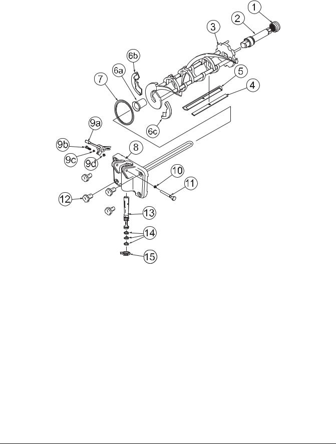
Beater Door Assembly - Soft Serve Side
ITEM |
DESCRIPTION |
PART NO. |
|
|
|
1 |
SEAL--DRIVE SHAFT |
032560 |
|
|
|
2 |
DRIVE SHAFT |
032564 |
|
|
|
3 |
BEATER A. |
X46231 |
|
|
|
4 |
CLIP--SCRAPER BLADE |
046236 |
|
|
|
5 |
SCRAPER BLADE |
046235 |
|
|
|
*6a |
BEARING--FRONT |
050348 |
|
|
|
6b |
SHOE--FRONT HELIX--REAR |
050346 |
|
|
|
6c |
SHOE--FRONT HELIX--FRONT |
050347 |
|
|
|
7 |
GASKET--DOOR |
048926 |
|
|
|
8 |
FREEZER DOOR A. |
X51531--9 |
|
|
|
9 |
DRAW HANDLE--ADJ. |
X44212 |
|
|
|
ITEM |
DESCRIPTION |
PART NO. |
|
|
|
9a |
DRAW HANDLE |
044197 |
|
|
|
9b |
SCREW--ADJUSTMENT |
055092 |
|
|
|
9c |
O--RING--ADJ. SCREW |
015872 |
|
|
|
9d |
NUT--5/16 --24 JAM |
029639--BLK |
|
|
|
10 |
O--RING--PIVOT PIN |
016272 |
|
|
|
11 |
PIVOT PIN A. |
X22820 |
|
|
|
12 |
HAND SCREW (STUD NUT) |
021508 |
|
|
|
13 |
DRAW VALVE A. |
X33582 |
|
|
|
14 |
O--RING--DRAW VALVE |
014402 |
|
|
|
15 |
DESIGN CAP |
014218 |
|
|
|
*USED W/FRONT HELIX SHOES 050346 & 050347 (KIT X50350)
Operator Parts Identification |
10 |
Model PH90 |
|
|
|
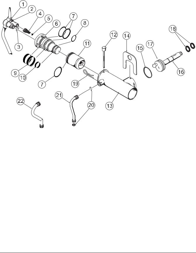
Air/Mix Pump - Shake Side & Soft Serve Sides
ITEM |
DESCRIPTION |
PART NO. |
|
|
|
|
|
1 -- 13 |
PUMP A.--COAX--SHAKE |
X45788--A |
|
|
|
||
PUMP A.--COAX--SOFT SRV |
X45316--B |
||
|
|||
|
|
|
|
1 |
TUBE A.--MIX INLET |
X45318 |
|
|
|
|
|
2 |
SEAL--AIR INLET FITTING |
045327 |
|
|
|
|
|
3 |
O--RING--MIX INLET FITTING |
015835 |
|
|
|
|
|
4 |
SPRING--TAPERED |
022456 |
|
|
|
|
|
5 |
POPPET--RUBBER |
022473 |
|
|
|
|
|
|
BODY A.--COAX VALVE *A* |
X46859--A |
|
6 |
SHAKE |
|
|
|
|
||
BODY A.--COAX VALVE *B* |
X46860--B |
||
|
|||
|
SOFT SERVE |
|
|
|
|
|
|
7 |
O--RING--2--1/8 OD |
020051 |
|
|
|
|
|
8 |
O--RING 1--3/8 OD |
018664 |
|
|
|
|
|
9 |
RING--CHECK 2” OD X 1/2 |
020050 |
|
|
|
|
|
10 |
RING--CHECK 1--1/4 OD X 3/8 |
033215 |
|
|
|
|
|
11 |
PISTON--PUMP--SHAKE |
032733 |
|
|
|
||
PISTON--PUMP--SOFT SERVE |
045319--B |
||
|
|||
|
|
|
ITEM |
DESCRIPTION |
PART NO. |
|
|
|
|
|
12 |
PIN A.--COAX PUMP |
X36950 |
|
|
|
|
|
13 |
CYLINDER A.--PUMP--SHAKE |
X44669 |
|
|
|
||
CYLINDER A.--PUMP--SOFT SV |
X44755 |
||
|
|||
|
|
|
|
14 |
CLIP--MIX PUMP RETAINER |
044641 |
|
|
|
|
|
15 |
O--RING 1--3/4 |
008904 |
|
|
|
|
|
16 |
SHAFT--DRIVE |
041948 |
|
|
|
|
|
17 |
CRANK--DRIVE |
039235 |
|
|
|
|
|
18 |
O--RING--DRIVE SHAFT |
048632 |
|
|
|
|
|
19 |
PIN--COTTER |
044731 |
|
|
|
|
|
20 |
O--RING--MIX FEED |
016132 |
|
|
TUBE--RED |
|
|
|
|
|
|
21 |
TUBE A.--PUMP FEED (SOFT |
X44666 |
|
|
SERVE) |
|
|
|
|
|
|
22 |
TUBE A.--PUMP FEED (SHAKE) |
X44615 |
|
|
|
|
Model PH90 |
11 |
Operator Parts Identification |
|
|
|
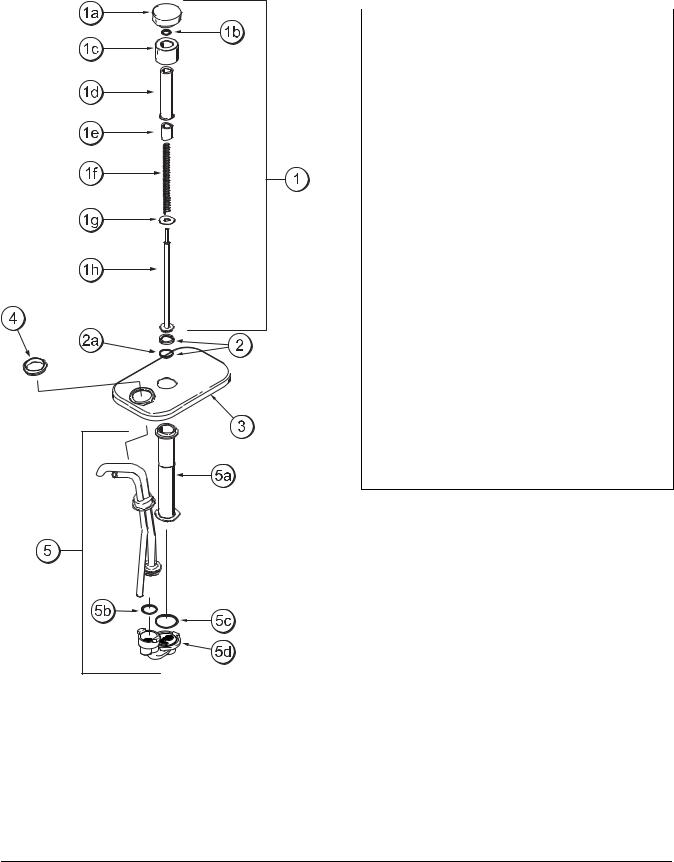
Pump A.-Syrup-Heated X53800-BRN/TAN
ITEM |
DESCRIPTION |
PART NO. |
|
|
|
|
|
1 |
PLUNGER A.-PUMP |
X36576-BRN |
|
PLUNGER A.-PUMP |
X36576-TAN |
||
|
|||
1a |
KNOB-PLUNGER-BROWN |
032762-BRN |
|
KNOB-PLUNGER-TAN |
032762-TAN |
||
|
|||
|
|
|
|
1b |
O-RING 9/16 OD |
016369 |
|
|
|
|
|
1c |
NUT-PLUNGER |
036577 |
|
|
|
|
|
1d |
TUBE-PLUNGER |
032757 |
|
|
|
|
|
1e |
INSERT-PLUNGER |
032758 |
|
|
|
|
|
1f |
SPRING-PLUNGER |
032761 |
|
|
|
|
|
1g |
WASHER-NYLON |
032760 |
|
|
|
|
|
1h |
PLUNGER |
036578 |
|
|
|
|
|
2 |
SEAL ASSEMBLY |
X33057 |
|
|
|
|
|
2a |
O-RING-13/16 OD X .103 |
019330 |
|
|
|
|
|
3 |
LID-PUMP |
036579 |
|
|
|
|
|
4 |
NUT-LOCK |
039680 |
|
|
|
|
|
5 |
PUMP A.-SYRUP HEATED |
X53798-SER |
|
5a |
CLYINDER-SYRUP PUMP |
051065 |
|
|
|
|
|
5b |
O-RING 1 ID X .103 W |
048148 |
|
|
|
|
|
5c |
O-RING 1-5/16 OD X .103 |
048149 |
|
|
|
|
|
5d |
BODY A.-PUMP VALVE |
054084 |
|
|
|
|
|
|
JAR-SYRUP-PLASTIC |
036573 |
|
|
|
|
|
|
JAR-SYRUP-STAINLESS |
036574 |
|
|
|
|
NOTE: X53800-BRN/TAN REPLACES
X42803-BRN/TAN & X48140-BRN/TAN
Operator Parts Identification |
12 |
Model PH90 |
|
|
|
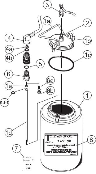
Syrup Tank
ITEM |
DESCRIPTION |
PART NO. |
|
|
|
|
|
1 |
SYRUP TANK (4 QT./3.8 LITER) |
045533 |
|
|
|
|
|
1a |
SYRUP TANK COVER |
035759--1 |
|
|
|
|
|
*1b |
TIP--NYLON--WHITE |
042747 |
|
|
|
||
TIP--NYLON--GREY |
024261 |
||
|
|||
|
|
|
|
1c |
GASKET--SYRUP TANK COVER |
016037 |
|
|
|
|
|
1d |
DIP TUBE |
015441--7 |
|
|
|
|
|
1d--1 |
O--RING--DIP TUBE |
018550 |
|
|
|
|
|
1e |
WASHER |
018595 |
|
|
|
|
|
2 |
CO2 QUICK DISCONNECT PLUG |
021077 |
|
|
|
|
|
3 |
QUICK DISCONNECT SOCKET |
021524 |
|
|
|
|
|
4 |
QUICK DISCONNECT SOCKET |
021026 |
|
|
|
|
|
**4a |
RESTRICTOR--SYRUP |
030917 |
|
|
|
|
|
4b |
GASKET--RUBBER |
023551 |
|
|
|
|
|
5 |
O--RING--SYRUP QD PLUG |
016030 |
|
|
|
|
|
6 |
SYRUP LINE QD PLUG |
021081 |
|
|
|
|
|
6a |
VALVE A.--QD PLUG |
021081--2 |
|
|
|
|
|
6b |
INSERT |
021081--1 |
|
|
|
|
|
7 |
SET (4)--SYRUP FLAVOR |
021523 |
|
|
DECALS |
|
|
|
|
|
|
8 |
DECAL--SYRUP TANK |
045533--1 |
|
|
|
|
*DUAL SUPPLIER -- ORDER AS NEEDED **NOT USED ON CHOCOLATE
|
|
|
|
|
|
|
|
|
|
|
|
|
|
|
|
|
|
|
|
|
|
|
|
|
|
|
|
|
|
|
|
|
|
|
|
|
|
|
|
|
|
|
|
|
|
|
|
|
|
|
|
|
|
|
|
|
|
|
|
|
|
|
Model PH90 |
13 |
Operator Parts Identification |
||||||
|
|
|
|
|
|
|
|
|
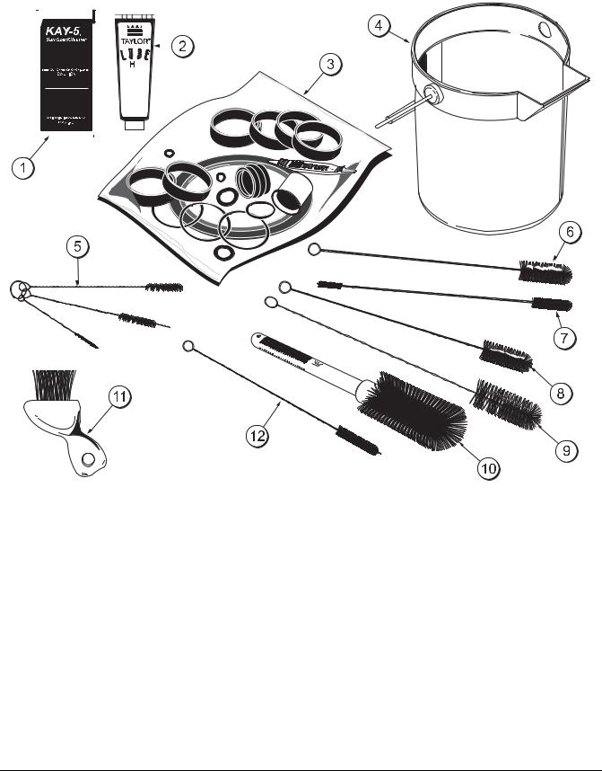
Accessories
|
|
|
|
|
|
|
|
|
|
|
|
|
|
|
|
|
|
|
|
|
|
|
|
|
|
|
|
|
|
|
|
|
|
|
|
|
|
|
|
|
|
|
|
|
|
|
|
|
|
|
|
|
|
|
|
|
|
|
|
|
|
|
|
|
|
|
|
|
|
|
|
|
|
|
|
|
|
|
|
|
|
|
|
|
|
|
|
|
|
|
|
|
|
|
|
|
|
|
|
|
|
|
|
|
|
|
|
|
|
|
|
|
|
|
|
|
|
|
|
|
|
|
|
|
|
|
|
|
|
|
|
|
|
|
|
|
|
|
|
|
|
|
|
|
|
|
|
|
|
|
|
|
|
|
|
|
|
|
|
|
|
|
|
|
|
|
|
|
|
|
|
|
|
|
|
|
|
|
|
|
|
|
|
|
|
|
|
|
|
|
|
|
|
|
|
|
|
|
|
|
|
|
|
|
|
|
|
|
|
|
|
|
|
|
|
|
|
|
|
|
|
|
|
|
|
|
|
|
|
|
|
|
|
|
|
|
|
|
|
|
|
|
|
|
|
|
|
|
|
|
|
|
|
|
|
|
|
|
|
|
|
|
|
|
|
|
|
|
|
|
|
|
|
|
|
|
|
|
|
|
|
|
|
|
|
|
|
|
|
|
|
|
|
|
|
|
|
|
|
|
|
|
|
|
|
|
|
|
|
|
|
|
|
|
|
|
|
|
|
|
|
|
|
|
|
|
|
|
|
|
|
|
|
|
|
|
|
|
|
|
|
|
|
|
|
|
|
|
|
|
|
|
|
|
|
|
|
|
|
|
|
|
|
|
|
|
|
|
|
|
|
|
|
|
|
|
|
|
|
|
|
|
|
|
|
|
|
|
|
|
|
|
|
|
|
|
|
|
|
|
|
|
|
|
|
|
|
|
|
|
|
|
|
|
|
|
|
|
|
|
|
|
|
|
|
|
|
|
|
|
|
|
|
|
|
|
|
|
|
|
|
|
|
|
|
|
|
|
|
|
|
|
|
|
|
|
|
|
|
|
|
|
|
|
|
|
|
|
|
|
|
|
|
|
ITEM |
DESCRIPTION |
PART NO. |
||||||||||||||||||||||
|
|
|
||||||||||||||||||||||
1 |
SANITIZER KAY-5 (125 PACKS) |
041082 |
||||||||||||||||||||||
2 |
LUBRICANT-TAYLOR HI-PERF. |
048232 |
||||||||||||||||||||||
|
|
|
||||||||||||||||||||||
3 |
KIT - TUNE UP |
X49463-12 |
||||||||||||||||||||||
|
|
|
||||||||||||||||||||||
4 |
PAIL-MIX 10 QT. |
013163 |
||||||||||||||||||||||
|
|
|
||||||||||||||||||||||
5 |
BRUSH-SET LVB |
050103 |
||||||||||||||||||||||
|
|
|
||||||||||||||||||||||
6 |
BRUSH-REAR BRG 1 IN.DX2 IN |
013071 |
||||||||||||||||||||||
|
|
|
||||||||||||||||||||||
7 |
BRUSH-DOUBLE ENDED |
013072 |
||||||||||||||||||||||
|
|
|
|
|
|
|
|
|
|
|
|
|
|
|
|
|
|
|
|
|
|
|
|
|
|
|
|
|
|
|
|
|
|
ITEM |
DESCRIPTION |
PART NO. |
|
|
|
|
|
8 |
BRUSH-DRAW VALVE 1”ODX2” |
013073 |
|
9 |
BRUSH-DRAW VALVE 1-1/2”OD |
014753 |
|
|
|
|
|
10 |
BRUSH-MIX PUMP BODY-3”X7” |
023316 |
|
|
|
|
|
11 |
BRUSH-END-DOOR-SPOUT-SS |
039719 |
|
|
|
|
|
12 |
BRUSH-1/2 IN. DIA. |
033059 |
|
|
|
|
|
* |
SANITIZER-STERA-SHEEN |
010425 |
|
|
|
|
|
*NOT SHOWN |
|
|
Operator Parts Identification |
14 |
Model PH90 |
|
|
|

Section 5 |
|
Important: To the Operator |
||||||||||||||||||||||||||||||
|
|
|
|
|
|
|
|
|
|
|
|
|
|
|
|
|
|
|
|
|
|
|
|
|
|
|
|
|
|
|
|
|
|
|
|
|
|
|
|
|
|
|
|
|
|
|
|
|
|
|
|
|
|
|
|
|
|
|
|
|
|
|
|
|
|
|
|
|
|
|
|
|
|
|
|
|
|
|
|
|
|
|
|
|
|
|
|
|
|
|
|
|
|
|
|
|
|
|
|
|
|
|
|
|
|
|
|
|
|
|
|
|
|
|
|
|
|
|
|
|
|
|
|
|
|
|
|
|
|
|
|
|
|
|
|
|
|
|
|
|
|
|
|
|
|
|
|
|
|
|
|
|
|
|
|
|
|
|
|
|
|
|
|
|
|
|
|
|
|
|
|
|
|
|
|
|
|
|
|
|
|
|
|
|
|
|
|
|
|
|
|
|
|
|
|
|
|
|
|
|
|
|
|
|
|
|
|
|
|
|
|
|
|
|
|
|
|
|
|
|
|
|
|
|
|
|
|
|
|
|
|
|
|
|
|
|
|
|
|
|
|
|
|
|
|
|
|
|
|
|
|
|
|
|
|
|
|
|
|
|
|
|
|
|
|
|
|
|
|
|
|
|
|
|
|
|
|
|
|
|
|
|
|
|
|
|
|
|
|
|
|
|
|
|
|
|
|
|
|
|
|
|
|
|
|
|
|
|
|
|
|
|
|
|
|
|
|
|
|
|
|
|
|
|
|
|
|
|
|
|
|
|
|
|
|
|
|
|
|
|
|
|
|
|
|
|
|
|
|
|
|
|
|
|
|
|
|
|
|
|
|
|
|
|
|
|
|
|
|
|
|
|
|
|
|
|
|
|
|
|
|
|
|
|
|
|
|
|
|
|
|
|
|
|
|
|
|
|
|
|
|
|
|
|
|
|
|
|
|
|
|
|
|
|
|
|
|
|
|
|
|
|
|
|
|
|
|
|
|
|
|
|
|
|
|
|
|
|
|
|
|
|
|
|
|
|
|
|
|
|
|
|
|
|
|
|
|
|
|
|
|
|
|
|
|
|
|
|
|
|
|
|
|
|
|
|
|
|
|
|
|
|
|
|
|
|
|
|
|
|
|
|
|
|
|
|
|
|
|
|
|
|
|
|
|
|
|
|
|
|
|
|
|
|
|
|
|
|
|
|
|
|
|
|
|
|
|
|
|
|
|
|
|
|
|
|
|
|
|
|
|
|
|
|
|
|
|
|
|
|
|
|
|
|
|
|
|
|
|
|
|
|
|
|
|
|
|
|
|
|
|
|
|
|
|
|
|
|
|
|
|
|
|
|
|
|
|
|
|
|
|
|
|
|
|
|
|
|
|
|
|
|
|
|
|
|
|
|
|
|
|
|
|
|
|
|
|
|
|
|
|
|
|
|
|
|
ITEM |
DESCRIPTION |
|
|
1 |
Power Switch (Toggle) |
2 |
Indicator Lights (PCB A.--LED) |
|
|
3 |
Flavor Selector Keypad |
|
(Switch--Membrane) |
|
|
4 |
Liquid Crystal Display |
|
|
5 |
Keypads (Switch--Membrane) |
|
|
6 |
Heater Switches (Toggle) |
|
|
Symbol Definitions
To better communicate in the International arena, the words on many of our operator switches and buttons have symbols to indicate their functions. Your Taylor equipment is designed with these International symbols.
The following chart identifies the symbol definitions.
= OFF
= ON
= CALIBRATE
=WASH
=PUMP
=AUTO
=MENU
=MIX LOW
=MIX OUT
=HEAT MODE
=CLEAN MANUALLY/BRUSH CLEAN
=CHOCOLATE
=STRAWBERRY
=VANILLA
=OPTIONAL
Model PH90 |
15 |
Important: To the Operator |
|
|
|

Power Switch
The power switch is located under the control panel on the left hand side of the unit. When placed in the ON position, the power switch allows Softech panel operation.
Liquid Crystal Display
Located on the front control panel is the Liquid Crystal Display (LCD). The LCD is used to show what mode of operation the freezer is in and whether or not there is sufficient mix.
Indicator Lights
Mix Low -- When the MIX LOW light begins to flash, it indicates the mix hopper has a low supply of mix and should be refilled as soon as possible. The word “LOW” will also display on the LCD indicator next to the word “MIX”.
Mix Out -- When the MIX OUT light begins to flash, it indicates the mix hopper has been almost completely exhausted and has an insufficient supply of mix to operate the freezer. The word “OUT” will also display on the LCD indicator next to the word “MIX”. At this time the AUTO mode is locked out and the freezer will be placed in the STANDBY mode. To initiate the refrigeration system, add mix to the mix hopper and press the AUTO keypad. The freezer will automatically begin operation.
Heat Mode -- When the HEAT MODE light is flashing, it indicates that the freezer is in the process of a heat cycle.
Clean Manually -- When the CLEAN MANUALLY light is flashing, it indicates that the machine must be disassembled and brush cleaned within 24 hours.
When all four indicator lights are flashing, this signifies a locked condition. When MIX LOW and MIX OUT lights are flashing only, this signifies an unlocked condition.
Flavor Selector Keypad
Four shake flavors are offered from the Model PH90 freezer: chocolate, strawberry, vanilla (unflavored product), and an optional flavor. Press the desired shake flavor keypad and open the draw valve. Product and syrup will automatically blend to produce the chosen flavor.
Heater Switch
The heater switch is located under the control panel on the right hand side of the unit. When placed in the ON position, the heater switch controls power to the heated syrup topping rail.
Reset Mechanism
The reset buttons are located in the syrup compartment, behind the syrup tanks. There is one for each side of the freezer.
The reset mechanism protects the beater motor from an overload condition. Should an overload occur, the reset mechanism will trip. To properly reset the freezer, place the power switch in the OFF position. Press the reset button firmly. Turn the power switch to the ON position. Clear the fault. Press the WASH keypad and observe the freezer’s performance. Open the side access panel to check if the beater motor is turning the drive shaft in a clockwise (from the operator end) direction without binding.
 Do not use metal objects to press the reset button. Failure to follow this instruction may result in electrocution.
If it is turning properly, press the WASH keypad to cancel the cycle. Press the AUTO keypad on both sides of the machine to resume normal operation. If the freezer shuts down again, contact service technician.
Important: To the Operator |
16 |
Model PH90 |
|
|
|
Adjustable Draw Handle
The soft serve side of the freezer features an adjustable draw handle to provide the best portion control, giving a better, consistent quality to your product and controlling costs. The draw handle should be adjusted to provide a flow rate of 5 to 7--1/2 oz. of product by weight per 10 seconds. To INCREASE the flow rate, turn the screw COUNTERCLOCKWISE, and CLOCKWISE to DECREASE the flow rate. In addition, for purposes of SANITIZING and RINSING, the flow rate can be increased by removing the pivot pin and placing the restrictive bar on the TOP. When drawing product, always have the restrictive bar on the BOTTOM.
 IMPORTANT: Once the draw rate is set, tighten the lock nut with a wrench.
Operating Screen Descriptions
When the machine is powered the system will initialize. The screen will display “INITIALIZING”. There will be four types of data the system will check: LANGUAGE, SYSTEM DATA, CONFIG DATA, and LOCKOUT DATA. During the INITIALIZING... LANGUAGE screen, the alarm will be on. If the system data, configuration data, or lockout history data has become corrupt, the following screen will alert the operator that the system settings may have been changed.
NVRAM FAULT
RESET TO DEFAULTS
PRESS SEL KEY
Once the system has initialized the SAFETY TIMEOUT screen is displayed and the alarm is turned on.
SAFETY TIMEOUT
ANY KEY ABORTS
This screen will be displayed, with the alarm on, for 60 seconds or until any keypad is pressed.
After the safety timeout has been completed, and the power switch is OFF, one of the following screens is displayed.
The first screen is displayed if the machine is not in a brush clean state. If any of the requirements for a brush clean have not been met, the time displayed will remain at 5:00 minutes. When all the requirements for a brush cleaning are met, and the five minutes expire, the screen will change to the second screen, which is the standard power switch OFF screen.
|
POWER SWITCH OFF |
|
OUT |
TIME: 4:40 |
OUT |
68.5 |
HOPPER |
62.1 |
69.5 |
BARREL |
67.7 |
|
|
|
POWER SWITCH OFF
-= - = - = - = - = - UNIT CLEANED
When the power switch is set in the ON position, the system mode of operation screen is displayed. In this example, the machine is ON, but no mode of operation has been selected. The second line of the display indicates whether there is a sufficient supply of mix in the hopper or if there is a LOW or OUT mix condition. The third line of the display shows the temperature of the mix hopper. After pressing the AUTO keypad, the last line of the display shows the month and date (MM = month, DD = day) that the machine needs to be disassembled and brush cleaned.
OFF |
:MODE: |
OFF |
OK |
:MIX: |
OK |
40.0F |
HOPPER |
40.0F |
BRUSH CLEAN ON: |
MM/DD |
|
|
|
|
Model PH90 |
17 |
Important: To the Operator |
|
|
|

This display indicates the freezer is operating in 3 different modes. The following information is given:
The left side of the freezer is operating in the STANDBY mode, and the mix level in the hopper is OUT. The right side is operating in the WASH and PUMP modes, and the mix level in the hopper is LOW. The temperature of the mix in both hoppers is 40_F. (4.4_C.), and the machine needs to be brush cleaned on October 31st.
STANDBY |
:MODE: |
WSH-PMP |
OUT |
:MIX: |
LOW |
40.0F |
HOPPER |
40.0F |
BRUSH CLEAN ON: |
10/31 |
|
The following displays pertain to the HEAT cycle:
While in the heating phase, you will see this display. It shows the present temperature of the hopper.
HEAT |
:MODE: |
HEAT |
HEAT |
:PHASE: |
HEAT |
140.0F |
HOPPER |
140.0F |
BRUSH CLEAN ON: |
MM/DD |
|
 DO NOT draw product or attempt to disassemble the unit during the HEAT cycle. The product is hot and under extreme pressure.
The mix temperature must be raised above 151_F. (66.1_C.) within 90 minutes or the freezer will be locked in STANDBY, and the cycle failure display will appear.
In the example, the hopper temperature is 140_F. (60_C.). The phase shows that the machine is in the HEAT phase of the treatment cycle.
When the heating phase is complete, the freezer goes into the holding phase of the cycle. The holding phase will hold the temperature above 151_F. (66.1_C.) for a minimum of 30 minutes.
In this example, the hopper temperature is 151_F. (66.1_C.).
HEAT |
:MODE: |
HEAT |
HOLD |
:PHASE: |
HOLD |
151.0F |
HOPPER |
151.0F |
BRUSH CLEAN ON: |
MM/DD |
|
|
|
|
010917 |
|
|
The final phase of the heat treatment cycle is the cooling phase. Now the freezer must cool the mix below 41_F. (5_C.). If the product fails to cool in 2 hours, the freezer will lock out.
This example illustrates that the temperature is being lowered, but has not yet reached the set point.
HEAT |
:MODE: |
HEAT |
COOL |
:PHASE: |
COOL |
55.0F |
HOPPER |
55.0F |
BRUSH CLEAN ON: |
MM/DD |
|
When the entire heat cycle has been completed, the normal display will appear, showing the machine in the STANDBY mode. The machine may now be placed in AUTO or left in STANDBY.
STANDBY |
:MODE: |
STANDBY |
OK |
:MIX: |
OK |
41.0F |
HOPPER |
41.0F |
BRUSH CLEAN ON: |
MM/DD |
|
Hard Lock: There are two causes for a hard lock:
1.Fourteen days have elapsed since the last brush cleaning. The following screen will be displayed.
14 DAY TIMEOUT CLEANING REQ’D FREEZER LOCKED PRESS SEL KEY
2.There has been a thermistor failure (freezing cylinder, hopper, or glycol) during the heat treatment process.
SYSTEM FAULT
SERVICE REQ’D
FREEZER LOCKED
PRESS SEL KEY
All four LED’s on the front of the freezer will light. Press the SEL keypad.
Important: To the Operator |
18 |
Model PH90 |
|
|
|

The next display is the screen which will appear after the failure message. To comply with health codes, heat treatment system freezers must complete a heat treatment cycle daily, and must also be brushed cleaned every 14 days. Brush cleaning is the normal disassembly and cleaning procedure. Failure to follow these guidelines will cause the control to lock the freezer out of the AUTO mode. Press the WASH keypad.
NO AUTO OPERATION
ALLOWED UNTIL
BRUSH CLEANING
PRESS WASH KEY
The next display is the screen which will appear after the brush cleaning message and illustrates that the control is in the OFF mode and the machine needs to be disassembled and brush cleaned.
Once the unit is unlocked, only the mix out and mix low LED’s will light.
OFF |
:MODE: |
OFF |
OK |
:MIX: |
OK |
41.0F |
HOPPER |
41.0F |
|
FREEZER LOCKED |
|
Soft Lock: If a heat treatment cycle has not been initiated within the last 24 hours, all four LED’s on the front of the machine will light and a message will appear on the LCD. Line 3 of the LCD will indicate the reason the message appears. Following are the variable messages which will appear on line 3:
1.POWER SWITCH OFF: Power switch was in the OFF position.
2.MIX OUT PRESENT: There was mix out condition present.
3.AUTO OR STANDBY OFF: The unit was not in the AUTO or STANDBY mode.
4.NO HEAT CYCLE TRIED: A heat treatment cycle was not attempted in the last 24 hours. (AUTO HEAT TIME was advanced, or a power loss was experienced at the time the cycle was to occur, or a heat cycle failure not due to a thermistor failure.)
NO HEAT TREAT START
BECAUSE
VARIABLE MESSAGE
PRESS SEL KEY
If the following screen appears, a soft lock has occurred during the heat treatment cycle.
HEAT TREAT CYCLE
FAILURE
FREEZER LOCKED
PRESS SEL KEY
If the temperature of the product has not fallen below 41_F (5_C) by the end of the COOL cycle, the following screen will appear.
PRODUCT OVER TEMP
FREEZER LOCKED
PRESS SEL KEY
Press the SEL keypad to advance to the next display.
When one of these messages appears, automatic freezer operation cannot take place until the freezer is disassembled and brush cleaned or has completed a heat treatment cycle. The next display will instruct the operator to start a heat treatment cycle manually (by pressing the AUTO keypad), or to disassemble and brush clean the freezer. If the AUTO keypad is pressed, the freezer will automatically start the heat treatment cycle and only the heat cycle LED will light.
NO AUTO OPERATION
ALLOWED. PRESS
AUTO FOR HEAT CYCLE
WASH TO BRUSH CLEAN
Model PH90 |
19 |
Important: To the Operator |
|
|
|

If the WASH keypad is pressed, the next display will appear and the freezer will have to be disassembled and brush cleaned.
OFF |
:MODE: |
OFF |
OK |
:MIX: |
OK |
41.0F |
HOPPER |
41.0F |
FREEZER LOCKED |
|
|
Once the freezer is unlocked by starting a heat treatment cycle, only the heat cycle LED will light. If the freezer is unlocked by brush cleaning, the mix low and mix out LED’s will light.
Operator Menu
The OPERATOR MENU is used to enter the operator function displays. To access the OPERATOR MENU, simply press the MENU keypad. The cursor will flash over the letter “A” indicating that this is screen “A”. To select a different screen, use the arrow keypads and move the cursor to the desired screen selection and press the SEL keypad.
OPERATOR MENU |
|
A B C D E F G H I J |
|
EXIT FROM MENU |
|
<- - - - - -> |
SEL |
Screen “B” is FAULT DESCRIPTION. The fault description will indicate if there is a fault with the freezer and the side of the freezer where the fault occurred. To clear the tone for any faults which have been corrected, press the left arrow keypad. To see if there is more than one fault per cylinder, press the SEL keypad. When the last fault is displayed, the control will return to the OPERATOR MENU. To return to the main screen, move the cursor to “A” and press the SEL keypad again. Listed below are the variable messages which will appear, along with the corrective action:
1.NO FAULT FOUND: There was no fault found in the freezer. Nothing will appear on the screen after this variable message appears.
2.BEATER OVERLOAD: Press the reset button firmly. Clear the tone.
3.HPCO COMPRESSOR: Place the power switch in the OFF position. Wait 5 minutes for the machine to cool. Place the power switch in the ON position. Clear the tone.
4.COMP ON TOO LONG: Place the power switch in the OFF position. Call service technician. Clear the tone.
5.HOPPER THERM BAD: Place the power switch in the OFF position. Call service technician.
6.BARREL THERM BAD: Place the power switch in the OFF position. Call service technician.
7.GLYCOL THERM BAD: Place the power switch in the OFF position. Call service technician.
8.HOPPER OVER TEMP: The hopper temperature has risen too high as follows. Clear the tone.
a.The hopper temperature reaches 41_F. (5_C.) or higher after a power failure.
b.The hopper temperature has not fallen below 41_F. (5_C.) by the end of the COOL phase in the heat cycle.
9.BARREL OVER TEMP: The barrel temperature has risen too high as follows. Clear the tone.
a.The barrel temperature reaches 41_F. (5_C.) or higher after a power failure.
b.The barrel temperature has not fallen below 41_F. (5_C.) by the end of the COOL phase in the heat cycle.
10.POWER FAILURE: This message will appear in the FAULT DESCRIPTION if a power failure has occurred. Clear the tone.
FAULT DESCRIPTION |
|
L: VARIABLE MESSAGE |
|
R: VARIABLE MESSAGE |
|
CLR |
SEL |
Important: To the Operator |
20 |
Model PH90 |
|
|
|

Screen “C” is SET CLOCK. This screen will display the current date and time. The date and time may only be changed after the freezer has been manually brush cleaned but before it has been placed in the AUTO mode. Move the cursor under the number you wish to change. Press the plus keypad to increase the number; press the minus keypad to decrease the number. When the desired time and date appears, press the SEL keypad once to return to the OPERATOR MENU.
SET CLOCK |
|
|
|
10:21 AM |
11/07/1999 |
|
|
- - |
|
|
|
<- - - - - -> |
+++ |
- - - |
SEL |
|
|
|
|
If an illegal date is entered, the following screen will appear. The correct date must be entered before leaving this display.
SET CLOCK |
|
|
|
10:34 AM |
02/30/1999 |
|
|
- - |
INVALID DATE |
|
|
<- - - - - -> |
+++ |
- - - |
SEL |
|
|
|
|
Screen “D” is SYSTEM INFORMATION. The first screen will indicate the software version used in the unit.
SOFTWARE VERSION
PH90 Control UVC2
Version 2.00
SEL
Press the SEL keypad to view the second screen of the SYSTEM INFORMATION display. This screen will indicate the Bill of Material number and serial number for the unit. Press the SEL keypad once to return to the Operator Menu.
B.O.M. |
PH9033B000 |
S/N |
J0000000 |
SEL
Screen “E” is AUTO HEAT TIME. This screen is used to set the time of day in which the heat treatment cycle will start. Move the cursor under the number you wish to change. Press the plus keypad to increase the number; press the minus keypad to decrease the number. When the desired time appears, press the SEL keypad once to return to the OPERATOR MENU.
AUTO HEAT TIME |
|
|
TIME: 12:00 AM |
|
|
- - |
|
|
<- - - - - -> +++ |
- - - |
SEL |
Screen “F” is CURRENT CONDITIONS. This screen gives the viscosity of the product and the hopper and barrel temperatures. The last line of the display is the compressor countdown safety timer. The safety timer prevents the compressor from running more than 11 minutes (other than during the cooling phase of the heat treatment cycle).
Press the SEL keypad once to view the SERVINGS COUNTER screen.
VISC |
HOPPER |
BARREL |
0 |
38.5 |
28.5 |
0.0 |
38.5 |
18.0 |
TIME C |
11:00 |
11:00 |
|
|
|
The SERVINGS COUNTER screen indicates the number of times the draw switch has closed (number of draws) since the last brush cleaning or since the last serving counter reset. A maximum of 32,767 draws can be recorded; an additional draw will cause the counter to restart at zero. Pressing the MENU keypad/SEL will return the display to the Operator Menu.
SERVINGS COUNTER
LEFT |
RIGHT |
12 |
15 |
|
SEL |
Draws are counted during the AUTO mode of operation only.
Model PH90 |
21 |
Important: To the Operator |
|
|
|

Screen “G” is HEAT CYCLE DATA. The information from the previous heat treatment cycles can be obtained through this screen. The most recent heat treatment cycle data will be shown first; press the plus keypad to scroll through the remaining heat cycle displays. If a heat treatment cycle failure should occur, a 2 character message will appear on the second line of the screen. Press the SEL keypad once to return to the OPERATOR MENU.
Listed below are the variable messages which could appear:
HT |
Failure in the heating phase. |
CL |
Failure in the cooling phase. |
TTFailure in meeting total heat treatment cycle time requirement.
MO |
Mix out condition. |
OP |
Operator interruption. |
PF |
Power failure. (If a power failure occurs, but |
|
the heat treatment cycle does not fail, an |
|
asterisk (*) will appear on the third line of the |
|
display.) |
BO |
Beater overload. |
HO |
High pressure cut--out. |
TH |
Failed thermistor probe. |
PS |
Power switch placed in the OFF position. |
ML |
Mix Low Condition. |
14 |
14 Day Timeout Occurred. |
RC |
Heat Cycle Record Cleared. |
11/07 |
02:00 |
05:09 |
|
HEAT |
OVER |
COOL |
XX |
01:09 |
00:45 |
01:14 |
|
TEMP AT END |
38.5 |
|
1 |
Pressing the left arrow keypad on any HEAT CYCLE DATA screen will cause the extended data screen to be displayed. This screen shows the hopper, barrel, and glycol temperatures, and the amount of time the freezer spent in the phases of the heat cycle when the heat cycle completed, or was terminated.
HOPPER |
BARREL |
GLYCOL |
151.0 |
134.5 |
98.1 |
153.0 |
136.0 |
|
PHASE TIME: 1:20 |
|
1 |
|
|
|
Screen “H” is the LOCKOUT HISTORY. This screen displays a history of the last 40 hard locks, soft locks, and brush clean dates. Page numbers are indicated in the upper right hand corner. Page 1 always contains the most recent failure. Press the PUMP keypad to cycle through the pages.
The second line of the screen displays the date and time a failure occurs. The third line indicates the reason for a failure, or will indicate a successful brush cleaning has occurred. Some failures occur for multiple reasons. When this occurs, a page will be generated for each reason. Press the SEL keypad once to return to the Operator Menu, or twice to return to the Main Screen.
LOCKOUT HISTORY |
|
1 |
|
11/21/99 |
02:08 |
|
|
SOFTLOCK ABORT |
|
|
|
|
+++ |
- - - |
SEL |
Screen “I” is the SERVICE MENU. This screen can only be accessed by a service technician.
Screen “J” is the STANDBY MODE. To place the left side of the freezer in the STANDBY mode, move the cursor under the word “yes”. Press the SEL keypad to execute the command and bring up the screen for the right side of the freezer. To place the right side of the freezer in the STANDBY mode, move the cursor under the word “yes”. When the SEL keypad is pressed, the command will be executed. To exit the STANDBY mode and place the unit in AUTO, press the AUTO keypad once. Pressing the AUTO keypad again will place the unit in the OFF mode.
STANDBY MODE |
|
|
LEFT |
YES |
NO |
|
|
- - - |
<- - - - - -> |
|
SEL |
|
|
|
Important: To the Operator |
22 |
Model PH90 |
|
|
|
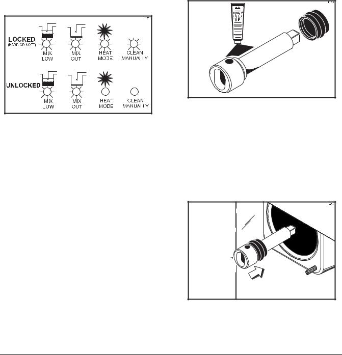
Section 6 |
Operating Procedures |
|
|
Equipment Set Up
Evaluate the condition of lights and screen messages (Hard Lock or Soft Lock, etc.) before performing opening procedures. If all four LED’s on the front of the unit are lit, the unit is locked. (See Figure 1.)
Figure 1
Freezing Cylinder Assembly -
Shake Side
 MAKE SURE POWER SWITCH IS IN THE “OFF” POSITION. Failure to do so may cause injury from hazardous moving parts, or electrocution.
Be certain your hands are sanitized before assembling the freezer.
With the parts tray available for the shake side:
Step 1
To install the drive shaft, lubricate the groove and shaft portion that comes in contact with the bearing on the beater drive shaft. Slide the seal over the shaft and groove until it snaps into place. DO NOT lubricate the square end of the drive shaft. Fill the inside portion of the seal with 1/4” more lubricant and evenly lubricate the end of the seal that fits onto the rear shell bearing. (See Figure 2.)
Note: When lubricating parts, use an approved food grade lubricant (example: Taylor Lube HP).
Figure 2
Install the drive shaft through the rear shell bearing in the freezing cylinder and engage the square end firmly into the gear box coupling. Be sure the drive shaft fits into the drive coupling without binding. (See Figure 3.)
Figure 3
Model PH90 |
23 |
Operating Procedures |
|
|
|
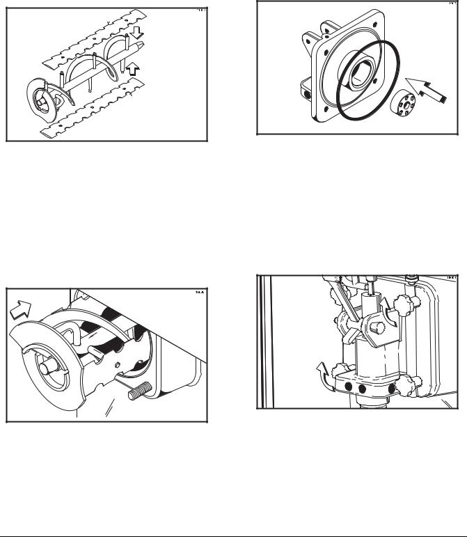
Check scraper blades for any nicks or signs of wear. If any nicks are present, replace the blades.
Note: Scraper blades should be replaced every 6 months.
If blades are in good condition, place each scraper blade over the holding pins on the beater assembly. (See Figure 4.)
Figure 4
Note: The holes in the scraper blade must fit over the pins to prevent damage.
Holding the blades on the beater assembly, insert the drive shaft of the beater assembly through the rear shell bearing in the freezing cylinder and engage the square end firmly into the drive coupling. (See Figure 5.)
Note: When properly seated, the beater will not protrude beyond the front of the freezing cylinder.
Figure 5
Step 2
Assemble the freezer door. Place the freezer door o--ring into the groove on the back of the freezer door. DO NOT lubricate the o--ring. Lubricate the outside diameter of the front bearing. Slide the front bearing into the door hub. (See Figure 6.)
Figure 6
Step 3
Install the freezer door. Position the freezer door on the 4 studs on the front of the freezing cylinder. Install the handscrews. Tighten equally in a criss--cross pattern to insure the door is snug. Do not over--tighten. (See Figure 7.)
Figure 7
Operating Procedures |
24 |
Model PH90 |
|
|
|
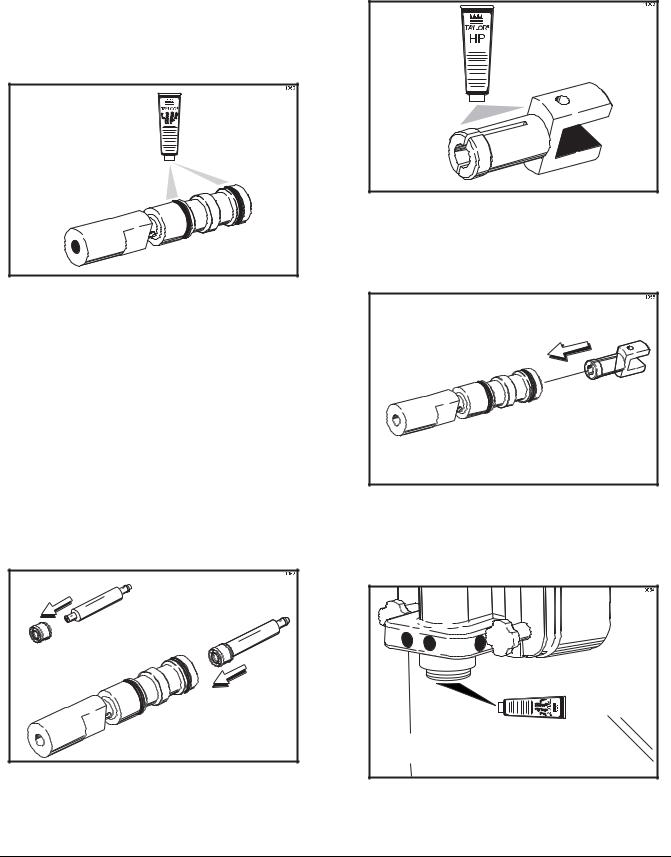
Step 4
Assemble the draw valve spinner assembly. Inspect draw valve o--rings for cuts or nicks. (Replace if cut or nicked.) If draw valve o--rings are in good condition, slide the two o--rings into the grooves of the draw valve and lubricate. (See Figure 8.)
Figure 8
Lubricate the outer diameter of the spinner shaft seal. Fill the cups on each end of the seal with lubricant. Insert the spinner shaft seal into the bottom of the draw valve as far as it will go. The spinner shaft seal should fit into the seal groove located inside the draw valve cavity.
Important: Inspect to see that the spinner shaft seal is correctly installed in the groove. A worn, missing, or improperly installed spinner shaft seal will cause product leakage out the top of the draw valve. (See Figure 9.)
Figure 9
Place an even coat of lubricant on the smaller end of the driven spinner. (See Figure 10.)
Figure 10
Squeezing the split end together, insert the driven spinner through the metal opening of the draw valve until it snaps into place. (See Figure 11.)
Figure 11
Step 5
Lubricate the inside of the freezer door spout, top and bottom. (See Figure 12.)
Figure 12
Model PH90 |
25 |
Operating Procedures |
|
|
|
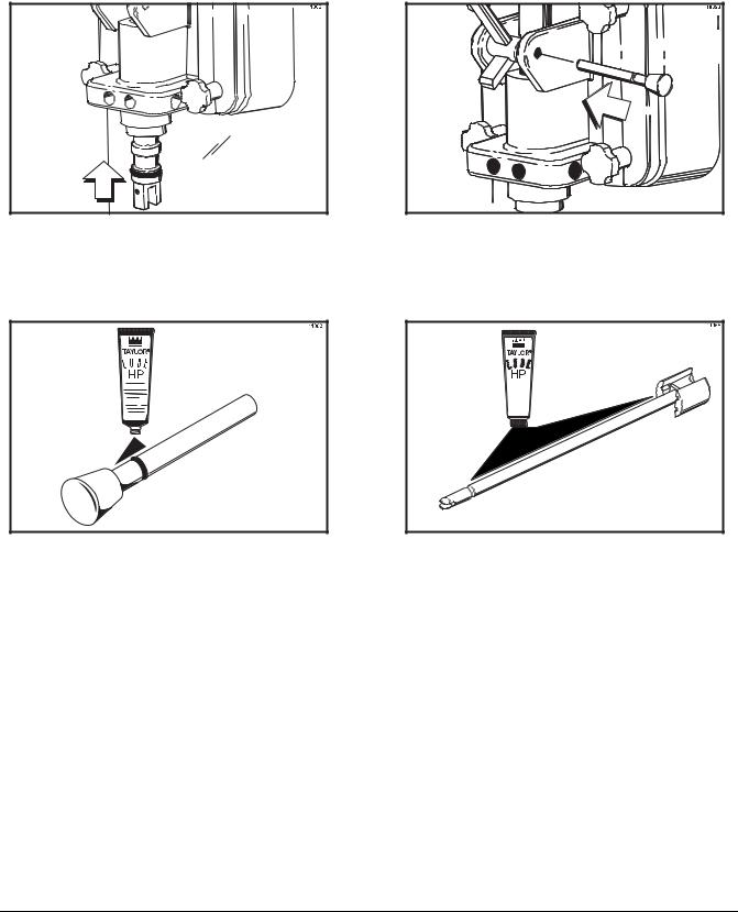
Install the draw valve spinner assembly. Insert the draw valve from the bottom until the slot in the draw valve which accepts the draw handle comes into view. (See Figure 13.)
Install the draw handle. With the stopping tab of the draw handle facing down, slide the fork of the draw handle into the slot of the draw valve. Secure the draw handle with the pivot pin. (See Figure 15.)
Figure 13
Step 6
Install and lubricate the pivot pin o--ring. (See Figure 14.)
Figure 15
Step 7
Install the spinner blade. Lubricate the shaft of the spinner blade up to the groove. (See Figure 16.)
Figure 14 |
Figure 16 |
Operating Procedures |
26 |
Model PH90 |
|
|
|
 Loading...