


Models PH71/PH84
Heat Treatment
Soft Serve Freezers
Operating Instructions
056389-M
1/21/02

Complete this page for quick reference when service is required:
Taylor Distributor:
Address:
Phone:
Service:
Parts:
Date of Installation:
Information found on the data label:
Model Number:
Serial Number:
Electrical Specs: Voltage |
|
Cycle |
|||||
Phase |
|
|
|
|
|
||
Maximum Fuse Size: |
|
|
|
|
A |
||
Minimum Wire Ampacity: |
|
|
|
|
A |
||
E January, 2002 Taylor All rights reserved. 056389--M

Table of Contents
Section 1 |
To the Installer . . . . . . . . . . . . . . . . . . . . . . . . . . . . . . . . . . . . . . . . . . . . |
1 |
Water Connections (Water Cooled Units Only) . . . . . . . . . . . . . . . . . . . . . . . . . . . . |
1 |
|
Air Cooled Units . . . . . . . . . . . . . . . . . . . . . . . . . . . . . . . . . . . . . . . . . . . . . . . . . . . . . . . |
1 |
|
Electrical Connections . . . . . . . . . . . . . . . . . . . . . . . . . . . . . . . . . . . . . . . . . . . . . . . . . |
1 |
|
Section 2 |
To the Operator . . . . . . . . . . . . . . . . . . . . . . . . . . . . . . . . . . . . . . . . . . . |
2 |
Compressor Warranty Disclaimer . . . . . . . . . . . . . . . . . . . . . . . . . . . . . . . . . . . . . . . |
2 |
|
Section 3 |
Safety . . . . . . . . . . . . . . . . . . . . . . . . . . . . . . . . . . . . . . . . . . . . . . . . . . . . |
3 |
Section 4 |
Operator Parts Identification . . . . . . . . . . . . . . . . . . . . . . . . . . . . . . . |
4 |
PH71 . . . . . |
. . . . . . . . . . . . . . . . . . . . . . . . . . . . . . . . . . . . . . . . . . . . . . . . . . . . . . . . . . . |
4 |
PH84 . . . . . |
. . . . . . . . . . . . . . . . . . . . . . . . . . . . . . . . . . . . . . . . . . . . . . . . . . . . . . . . . . . |
6 |
Beater Door Assembly -- PH71 . . . . . . . . . . . . . . . . . . . . . . . . . . . . . . . . . . . . . . . . . . |
8 |
|
Beater Door Assembly -- PH84 . . . . . . . . . . . . . . . . . . . . . . . . . . . . . . . . . . . . . . . . . . |
9 |
|
Pump Assembly X45316--B . . . . . . . . . . . . . . . . . . . . . . . . . . . . . . . . . . . . . . . . . . . . |
10 |
|
Accessories |
. . . . . . . . . . . . . . . . . . . . . . . . . . . . . . . . . . . . . . . . . . . . . . . . . . . . . . . . . . |
11 |
Section 5 |
Important: To the Operator . . . . . . . . . . . . . . . . . . . . . . . . . . . . . . . . . |
12 |
Symbol Definitions . . . . . . . . . . . . . . . . . . . . . . . . . . . . . . . . . . . . . . . . . . . . . . . . . . . . |
13 |
|
Power Switch . . . . . . . . . . . . . . . . . . . . . . . . . . . . . . . . . . . . . . . . . . . . . . . . . . . . . . . . . |
13 |
|
Liquid Crystal Display . . . . . . . . . . . . . . . . . . . . . . . . . . . . . . . . . . . . . . . . . . . . . . . . . . |
13 |
|
Indicator Lights . . . . . . . . . . . . . . . . . . . . . . . . . . . . . . . . . . . . . . . . . . . . . . . . . . . . . . . |
13 |
|
Reset Mechanism . . . . . . . . . . . . . . . . . . . . . . . . . . . . . . . . . . . . . . . . . . . . . . . . . . . . . |
13 |
|
Air/Mix Pump Reset Mechanism . . . . . . . . . . . . . . . . . . . . . . . . . . . . . . . . . . . . . . . . |
14 |
|
Adjustable Draw Handle . . . . . . . . . . . . . . . . . . . . . . . . . . . . . . . . . . . . . . . . . . . . . . . |
14 |
|
Operating Screen Descriptions . . . . . . . . . . . . . . . . . . . . . . . . . . . . . . . . . . . . . . . . . . |
14 |
|
Operator Menu . . . . . . . . . . . . . . . . . . . . . . . . . . . . . . . . . . . . . . . . . . . . . . . . . . . . . . . |
17 |
|
Models PH71/PH84 |
Table of Contents |
|
|

Table of Contents - Page 2
Section 6 |
Operating Procedures . . . . . . . . . . . . . . . . . . . . . . . . . . . . . . . . . . . . . |
21 |
Assembly . |
. . . . . . . . . . . . . . . . . . . . . . . . . . . . . . . . . . . . . . . . . . . . . . . . . . . . . . . . . . . |
21 |
Air/Mix Pump Assembly . . . . . . . . . . . . . . . . . . . . . . . . . . . . . . . . . . . . . . . . . . . . . . . . |
25 |
|
Sanitizing . |
. . . . . . . . . . . . . . . . . . . . . . . . . . . . . . . . . . . . . . . . . . . . . . . . . . . . . . . . . . . |
28 |
Priming . . . |
. . . . . . . . . . . . . . . . . . . . . . . . . . . . . . . . . . . . . . . . . . . . . . . . . . . . . . . . . . . |
31 |
Daily Closing Procedures . . . . . . . . . . . . . . . . . . . . . . . . . . . . . . . . . . . . . . . . . . . . . . |
32 |
|
Daily Opening Procedures . . . . . . . . . . . . . . . . . . . . . . . . . . . . . . . . . . . . . . . . . . . . . . |
33 |
|
Manual Brush Cleaning . . . . . . . . . . . . . . . . . . . . . . . . . . . . . . . . . . . . . . . . . . . . . . . . |
34 |
|
Draining Product From The Freezing Cylinder . . . . . . . . . . . . . . . . . . . . . . . . . . . . |
35 |
|
Rinsing . . . |
. . . . . . . . . . . . . . . . . . . . . . . . . . . . . . . . . . . . . . . . . . . . . . . . . . . . . . . . . . . |
35 |
Hopper Cleaning and Sanitizing . . . . . . . . . . . . . . . . . . . . . . . . . . . . . . . . . . . . . . . . . |
36 |
|
Disassembly . . . . . . . . . . . . . . . . . . . . . . . . . . . . . . . . . . . . . . . . . . . . . . . . . . . . . . . . . . |
36 |
|
Brush Cleaning . . . . . . . . . . . . . . . . . . . . . . . . . . . . . . . . . . . . . . . . . . . . . . . . . . . . . . . |
37 |
|
Section 7 |
Important: Operator Checklist . . . . . . . . . . . . . . . . . . . . . . . . . . . . . . |
38 |
During Cleaning and Sanitizing . . . . . . . . . . . . . . . . . . . . . . . . . . . . . . . . . . . . . . . . . |
38 |
|
Troubleshooting Bacterial Count: . . . . . . . . . . . . . . . . . . . . . . . . . . . . . . . . . . . . . . . . |
38 |
|
Regular Maintenance Checks: . . . . . . . . . . . . . . . . . . . . . . . . . . . . . . . . . . . . . . . . . . |
38 |
|
The Air/Mix Pump Checklist . . . . . . . . . . . . . . . . . . . . . . . . . . . . . . . . . . . . . . . . . . . . |
39 |
|
Winter Storage . . . . . . . . . . . . . . . . . . . . . . . . . . . . . . . . . . . . . . . . . . . . . . . . . . . . . . . . |
39 |
|
Section 8 |
Troubleshooting Guide . . . . . . . . . . . . . . . . . . . . . . . . . . . . . . . . . . . . . . |
40 |
Section 9 |
Parts Replacement Schedule . . . . . . . . . . . . . . . . . . . . . . . . . . . . . . . . |
44 |
Section 10 |
Parts List . . . . . . . . . . . . . . . . . . . . . . . . . . . . . . . . . . . . . . . . . . . . . . . . . . |
45 |
Wiring Diagrams . . . . . . . . . . . . . . . . . . . . . . . . . . . . . . . . . . . . . . . . . . . . . . . . . . . . . . |
57 |
|
Note: Continuing research results in steady improvements; therefore, information in this manual is subject to change without notice.
Table of Contents |
Models PH71/PH84 |
|
|

Section 1 |
To the Installer |
This machine is designed for indoor use only.
 DO NOT install the machine in an area where a water jet could be used. Failure to follow this instruction may result in serious electrical shock.
Water Connections
(Water Cooled Units Only)
An adequate cold water supply must be provided with a hand shut-off valve. On the underside rear of the base pan, two 3/8” I.P.S. (for single-head units) or two 1/2” I.P.S. (for double-head units) water connections for inlet and outlet have been provided for easy hook-up. 1/2” inside diameter water lines should be connected to the machine. (Flexible lines are recommended, if local codes permit.) Depending on local water conditions, it may be advisable to install a water strainer to prevent foreign substances from clogging the automatic water valve. There will be only one water “in” and one water “out” connection. DO NOT install a hand shut-off valve on the water “out” line! Water should always flow in this order: first, through the automatic water valve; second, through the condenser; and third, through the outlet fitting; to an open trap drain.
In the United States, this equipment is intended to be installed in accordance with the National Electrical Code (NEC), ANSI/NFPA 70--1987. The purpose of the NEC code is the practical safeguarding of persons and property from hazards arising from the use of electricity. This code contains provisions considered necessary for safety. Compliance therewith and proper maintenance will result in an installation essentially free from hazard!
In all other areas of the world, equipment should be installed in accordance with the existing local codes. Please contact your local authorities.
Stationary appliances which are not equipped with a power cord and a plug or other device to disconnect the appliance from the power source must have an all--pole disconnecting device with a contact gap of at least 3 mm installed in the external installation.
 CAUTION: THIS EQUIPMENT MUST BE PROPERLY GROUNDED! FAILURE TO DO SO CAN RESULT IN SEVERE PERSONAL INJURY FROM ELECTRICAL SHOCK!
Beater rotation must be clockwise as viewed looking into the freezing cylinder.
Air Cooled Units
Air cooled units require a minimum of 3” (76 mm) of |
Note: The following procedures should be |
|||
performed by a trained service technician. |
||||
clearance around all sides of the freezer to allow for |
||||
|
|
|
||
adequate air flow across the condensers. Failure to |
|
|
|
|
allow adequate clearance can reduce the refrigeration |
To correct the rotation on a |
three-phase unit, |
||
capacity of the freezer and possibly cause permanent |
||||
interchange any two incoming power supply lines at |
||||
damage to the compressors. |
||||
freezer main terminal block only. |
|
|
||
|
|
|
||
Electrical Connections |
To correct rotation on a single-phase unit, change the |
|||
leads inside the beater motor. (Follow the diagram |
||||
|
||||
Each freezer requires one power supply. Check the |
printed on the motor.) |
|
|
|
|
|
|
||
data label on the freezer for fuse, circuit ampacity and |
|
|
|
|
electrical specifications. Refer to the wiring diagram |
Electrical connections are made directly to the |
|||
provided inside of the electrical box, for proper power |
terminal block. The terminal block is provided in the |
|||
connections. |
main control box located behind the service panel. |
|||
|
|
050816 |
|
|
|
|
|
|
|
Models PH71/PH84 |
1 |
To the Installer |
||
|
|
|
|
|

Section 2 |
To the Operator |
|
|
The freezer you have purchased has been carefully engineered and manufactured to give you dependable operation. The Taylor Models PH71/PH84, freezers, when properly operated and cared for, will produce a consistent quality product. Like all mechanical products, this machine will require cleaning and maintenance. A minimum amount of care and attention is necessary if the operating procedures outlined in this manual are followed closely.
This Operator’s Manual should be read before operating or performing any maintenance on your equipment.
Your Taylor freezer will NOT eventually compensate and correct for any errors during the set-up or filling operations. Thus, the initial assembly and priming procedures are of extreme importance. It is strongly recommended that all personnel responsible for the equipment’s operation review these procedures in order to be properly trained and to make sure that there is no confusion.
In the event that you should require technical assistance, please contact your local authorized Taylor Distributor.
 If the crossed out wheeled bin symbol is affixed to this product, it signifies that this product is compliant with the EU Directive as well as other similar legislation in effect after August 13, 2005. Therefore, it must be collected separately after its use is completed, and cannot be disposed as unsorted municipal waste.
The user is responsible for returning the product to the appropriate collection facility, as specified by your local code.
For additional information regarding applicable local laws, please contact the municipal facility and/or local distributor.
Compressor Warranty Disclaimer
The refrigeration compressor(s) on this machine are warranted for the term indicated on the warranty card accompanying this machine. However, due to the Montreal Protocol and the U.S. Clean Air Act Amendments of 1990, many new refrigerants are being tested and developed, thus seeking their way into the service industry. Some of these new refrigerants are being advertised as drop-in replacements for numerous applications. It should be noted that, in the event of ordinary service to this machine’s refrigeration system, only the refrigerant specified on the affixed data label should be used. The unauthorized use of alternate refrigerants will void your compressor warranty. It will be the owner’s responsibility to make this fact known to any technician he employs.
It should also be noted that Taylor does not warrant the refrigerant used in its equipment. For example, if the refrigerant is lost during the course of ordinary service to this machine, Taylor has no obligation to either supply or provide its replacement either at billable or unbillable terms. Taylor does have the obligation to recommend a suitable replacement if the original refrigerant is banned, obsoleted, or no longer available during the five year warranty of the compressor.
The Taylor Company will continue to monitor the industry and test new alternates as they are being developed. Should a new alternate prove, through our testing, that it would be accepted as a drop-in replacement, then the above disclaimer would become null and void. To find out the current status of an alternate refrigerant as it relates to your compressor warranty, call the local Taylor Distributor or the Taylor Factory. Be prepared to provide the Model/Serial Number of the unit in question.
050816
To the Operator 2 Models PH71/PH84
Section 3 |
Safety |
|
|
We at Taylor Company are concerned about the safety of the operator when he or she comes in contact with the freezer and its parts. Taylor has gone to extreme efforts to design and manufacture built-in safety features to protect both you and the service technician. As an example, warning labels have been attached to the freezer to further point out safety precautions to the operator.
 IMPORTANT -- Failure to adhere to the following safety precautions may result in severe personal injury or death. Failure to comply with these warnings may damage the machine and its components. Component damage will result in part replacement expense and service repair expense.
To Operate Safely:
SDO NOT allow untrained personnel to operate this machine.
SDO NOT operate the freezer unless all service panels and access doors are restrained with screws.
SDO NOT remove the door, beater, scraper blades, or drive shaft unless the power switch is in the OFF position.
Failure to follow these instructions may result in severe personal injury from hazardous moving parts.
 DO NOT operate the freezer without reading this operator’s manual. Failure to follow this instruction may result in equipment damage, poor freezer performance, health hazards, or personal injury.
SDO NOT operate the freezer unless it is properly grounded.
SDO NOT operate the freezer with larger fuses than specified on the freezer data label.
SDO NOT attempt any repairs unless the main power supply to the freezer has been disconnected.
Failure to follow these instructions may result in electrocution. Contact your local authorized Taylor Distributor for service.
 DO NOT use a water jet to clean or rinse the freezer. Failure to follow this instruction may result in serious electrical shock.
SDO NOT put objects or fingers in door spout.
SUSE EXTREME CAUTION when removing the beater assembly.
Failure to follow these instructions may result in contaminated product or personal injury from blade contact.
 DO NOT draw product during the HEAT cycle because of high product temperatures.
 This freezer must be placed on a level surface. Failure to comply may result in personal injury or equipment damage.
DO NOT obstruct air intake and discharge openings: 3” (76 mm) minimum air space around all sides. Install the deflector provided to prevent recirculation of warm air. Failure to follow this instruction may cause poor freezer performance and damage to the machine.
NOISE LEVEL: Airborne noise emission does not exceed 78 dB(A) when measured at a distance of 1.0 meter from the surface of the machine and at a height of 1.6 meters from the floor.
|
|
050816 |
|
|
|
Models PH71/PH84 |
3 |
Safety |
|
|
|

Section 4 Operator Parts Identification
PH71
Operator Parts Identification |
4 |
Models PH71/PH84 |
|
|
|

PH71 Parts Identification
ITEM |
DESCRIPTION |
PART NO. |
|
|
|
1 |
COVER-HOPPER |
053809 |
|
|
|
2 |
PANEL A.-LOWER SIDE |
X39075-SER |
|
|
|
3 |
AGITATOR A. *HT*20 QT. |
X44797 |
|
|
|
4 |
PANEL-UPPER·SIDE-LEFT |
024426 |
|
|
|
5 |
STUD-NOSE CONE |
022822 |
|
|
|
6 |
PANEL-REAR |
048203 |
|
|
|
7 |
PANEL-UPPER SIDE RIGHT |
028823 |
|
|
|
8 |
PAN-DRIP 11-5/8 LONG |
027503 |
|
|
|
9 |
PANEL A.-LOWER SIDE |
X24424-SER |
|
|
|
10 |
ADAPTOR A.-CASTER |
X18915 |
|
|
|
11 |
PANEL-SERVICE |
045637 |
|
|
|
ITEM |
DESCRIPTION |
PART NO. |
|
|
|
12 |
TRAY-DRIP 14.8 |
046275 |
|
|
|
13 |
SHIELD-SPLASH-WIRE |
046177 |
|
|
|
14 |
PANEL A.-FRONT |
X45630 |
|
|
|
15 |
CASTER-SWV 5/8 STEM 4IN |
018794 |
|
|
|
16 |
SCREW |
011694 |
|
|
|
17 |
CARRIAGE BOLT |
012347 |
|
|
|
18 |
TRIM-REAR CORNER-RIGHT |
046391 |
|
|
|
19 |
LOUVER SIDE-R&L |
017471 |
|
|
|
20 |
PIN-RETAINER-HOPPER CVR |
043934 |
|
|
|
21 |
PAN-DRIP |
048435 |
|
|
|
*22 |
TRIM-REAR CORNER-LEFT |
046390 |
|
|
|
*NOT SHOWN
Models PH71/PH84 |
5 |
Operator Parts Identification |
|
|
|

PH84
Operator Parts Identification |
6 |
Models PH71/PH84 |
|
|
|
PH84 Parts Identification
ITEM |
DESCRIPTION |
PART NO. |
|
|
|
1 |
COVER-HOPPER |
053809 |
|
|
|
2 |
AGITATOR A. *HT*20 QT. |
X44797 |
|
|
|
3 |
PANEL-UPPER SIDE LEFT |
028822 |
|
|
|
4 |
PAN-DRIP 17-1/4”LONG |
027504 |
|
|
|
5 |
STUD-NOSE CONE |
022822 |
|
|
|
6 |
PANEL A.-SIDE LOWER LEFT |
X46447-SER |
|
|
|
7 |
PANEL-SERVICE |
046172 |
|
|
|
8 |
ADAPTOR A.-CASTER |
X18915 |
|
|
|
9 |
PANEL-REAR |
051076 |
|
|
|
10 |
PANEL-UPPER SIDE RIGHT |
028823 |
|
|
|
11 |
PANEL A.-SIDE LOWER RIGHT |
X46448-SER |
|
|
|
12 |
SHIELD-SPLASH-WIRE |
046170 |
|
|
|
ITEM |
DESCRIPTION |
PART NO. |
|
|
|
13 |
TRAY-DRIP 22-13/16 X 5-1/8 |
046171 |
|
|
|
14 |
PANEL A.-FRONT |
X46167 |
|
|
|
15 |
CASTER-SWV 5/8 STEM 4IN |
018794 |
|
|
|
16 |
LOUVER-SIDE-RIGHT |
017471 |
|
|
|
17 |
LOUVER-SIDE-LEFT |
028288 |
|
|
|
18 |
TRIM-REAR·CORNER·RIGHT |
013663 |
|
|
|
19 |
SCREW |
011694 |
|
|
|
20 |
PIN-RETAINER-HOPPER CVR |
043934 |
|
|
|
21 |
CARRIAGE BOLT |
012347 |
|
|
|
22 |
PAN-DRIP |
048204 |
|
|
|
*23 |
TRIM-REAR·CORNER·LEFT |
013761 |
|
|
|
*NOT SHOWN
Models PH71/PH84 |
7 |
Operator Parts Identification |
|
|
|
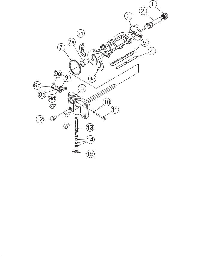
Beater Door Assembly - PH71
ITEM |
DESCRIPTION |
PART NO. |
|
|
|
1 |
SEAL--DRIVE SHAFT |
032560 |
|
|
|
2 |
DRIVE SHAFT |
032564 |
|
|
|
3 |
BEATER A. |
X46231 |
|
|
|
4 |
CLIP--SCRAPER BLADE |
046236 |
|
|
|
5 |
SCRAPER BLADE |
046235 |
|
|
|
*6a |
BEARING--FRONT |
050348 |
|
|
|
6b |
SHOE--FRONT HELIX--REAR |
050346 |
|
|
|
6c |
SHOE--FRONT HELIX--FRONT |
050347 |
|
|
|
7 |
GASKET--DOOR |
048926 |
|
|
|
8 |
FREEZER DOOR A. |
X51531-9 |
|
|
|
9 |
DRAW HANDLE--ADJ. |
X55095 |
|
|
|
ITEM |
DESCRIPTION |
PART NO. |
|
|
|
9a |
DRAW HANDLE |
044197 |
|
|
|
9b |
SCREW--ADJUSTMENT |
055092 |
|
|
|
9c |
O--RING--ADJ. SCREW |
015872 |
|
|
|
9d |
NUT-5/16 -24 JAM |
029639-BLK |
|
|
|
10 |
O--RING--PIVOT PIN |
016272 |
|
|
|
11 |
PIVOT PIN A. |
X22820 |
|
|
|
12 |
HAND SCREW (STUD NUT) |
021508 |
|
|
|
13 |
DRAW VALVE A. |
X33582 |
|
|
|
14 |
O--RING--DRAW VALVE |
014402 |
|
|
|
15 |
DESIGN CAP |
014218 |
|
|
|
*USED W/FRONT HELIX SHOES 050346 & 050347 (ORDER KIT X50350)
Operator Parts Identification |
8 |
Models PH71/PH84 |
|
|
|
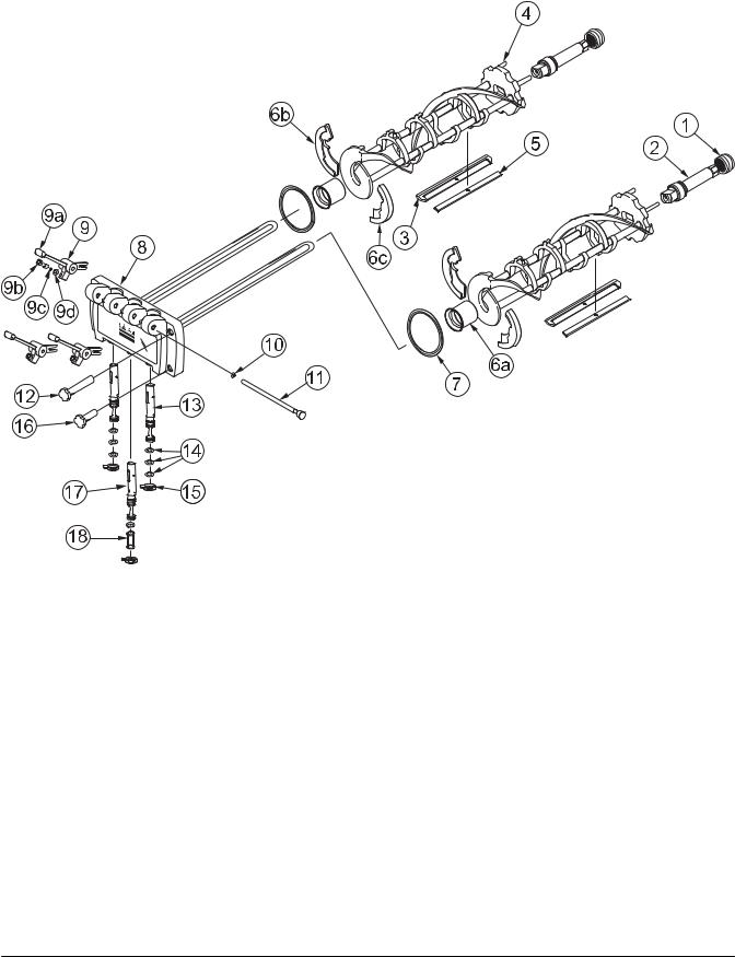
Beater Door Assembly - PH84
ITEM |
DESCRIPTION |
PART NO. |
|
|
|
1 |
SEAL-DRIVE SHAFT |
032560 |
|
|
|
2 |
SHAFT-BEATER |
032564 |
|
|
|
3 |
BLADE-SCRAPER |
046235 |
|
|
|
4 |
BEATER ASSEMBLY |
X46231 |
|
|
|
5 |
CLIP-SCRAPER·BLADE |
046236 |
|
|
|
*6a |
BEARING-FRONT |
050348 |
|
|
|
6b |
SHOE--FRONT HELIX--REAR |
050346 |
|
|
|
6c |
SHOE--FRONT HELIX--FRONT |
050347 |
|
|
|
7 |
GASKET-DOOR HT 4”-DOUBLE |
048926 |
|
|
|
8 |
DOOR-3 SPT |
X51532-11 |
|
|
|
9 |
HANDLE A.-DRAW-ADJ. STLS |
X33687 |
|
|
|
9a |
HANDLE-ADJUSTABLE |
028804 |
|
|
|
ITEM |
DESCRIPTION |
PART NO. |
|
|
|
9b |
SCREW-ADJUSTMENT-5/16-24 |
033662 |
|
|
|
9c |
O-RING-1/4 OD X .070W 50 |
015872 |
|
|
|
9d |
NUT-JAM 5/16-24 |
029639-BLK |
|
|
|
10 |
O-RING-5/16 OD X .070W |
016272 |
|
|
|
11 |
ROD A.-PIVOT |
X20683 |
|
|
|
12 |
NUT-STUD LONG |
034382 |
|
|
|
13 |
VALVE A.-DRAW*SELF CLEAN |
X33582 |
|
|
|
14 |
O-RING-7/8 OD X .103W |
014402 |
|
|
|
15 |
CAP-DESIGN-1.010”ID-6 POINT |
014218 |
|
|
|
16 |
NUT-STUD SHORT |
034383 |
|
|
|
17 |
VALVE A.-DRAW CENTER |
X37376 |
|
|
|
18 |
SEAL-DRAW VALVE |
034698 |
|
|
|
*USED W/FRONT HELIX SHOES 050346 & 050347 (KIT X50350)
Models PH71/PH84 |
9 |
Operator Parts Identification |
|
|
|
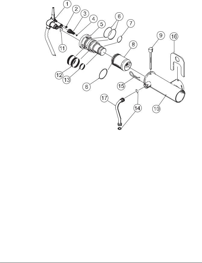
Pump Assembly X45316-B
PH71/PH84
ITEM |
DESCRIPTION |
PART NO. |
|
|
|
1 |
TUBE A.-MIX INLET |
X45318 |
|
|
|
2 |
SEAL--AIR INLET FITTING |
045327 |
|
|
|
3 |
SPRING |
022456 |
|
|
|
4 |
POPPET |
022473 |
|
|
|
5 |
BODY A.--COAX VALVE B |
X46860-B |
|
|
|
6 |
O--RING--PISTON/LVB (3) |
020051 |
|
|
|
7 |
O--RING--LVB |
018664 |
|
|
|
8 |
PISTON--COAX B |
045319-B |
|
|
|
9 |
PIN A.--COAX PUMP |
X36950 |
|
|
|
10 |
CYLINDER A.--PUMP |
X44755 |
|
|
|
ITEM |
DESCRIPTION |
PART NO. |
|
|
|
11 |
O--RING--MIX INLET TUBE |
015835 |
|
|
|
12 |
RING--CHECK--LVB (2) |
020050 |
|
|
|
13 |
RING-CHECK-LVB |
033215 |
|
|
|
|
SEPARATE ITEMS: |
|
|
|
|
14 |
O-RING-FEED TUBE |
016132 |
|
|
|
15 |
PIN--COTTER--HAIRPIN |
044731 |
|
|
|
16 |
CLIP--MIX PUMP RETAINER |
044641 |
|
|
|
|
TUBE A.--PUMP FEED (PH71) |
X44666 |
|
|
|
17 |
TUBE A.--PUMP FEED--L (PH84) |
X44662 |
|
TUBE A.--PUMP FEED--R (PH84) |
X44664 |
Operator Parts Identification |
10 |
Models PH71/PH84 |
|
|
|

Accessories
3

 048260
8
1
2
4
5
6
ITEM |
DESCRIPTION |
PART NO. |
|
|
|
|
|
1 |
BRUSH-MIX PUMP BODY-3 X 7 |
023316 |
|
|
|
|
|
2 |
BRUSH-END-DOOR-SPOUT |
039719 |
|
|
|
|
|
3 |
KIT A.-TUNE UP-PH71 |
X49463-8 |
|
|
|
||
KIT A.-TUNE UP-PH84 |
X49463-1 |
||
|
|||
|
|
|
|
4 |
BRUSH-DOUBLE ENDED |
013072 |
|
|
|
|
7
R
L U B E
H P
|
|
|
|
|
|
|
|
|
|
ITEM |
DESCRIPTION |
PART NO. |
||
|
|
|
|
|
5 |
BRUSH-REAR BRG 1IN.D X 2IN |
013071 |
|
|
|
|
|
|
|
6 |
BRUSH-DRAW VALVE 1”ODX2” |
013073 |
|
|
|
|
|
|
|
7 |
LUBRICANT-TAYLOR HI PERF. |
048232 |
|
|
|
|
|
|
|
8 |
PAIL-MIX 10 QT. |
013163 |
|
|
|
|
|
|
|
* |
SANITIZER·KAY-5·125·PKTS |
041082 |
|
|
|
|
|
|
|
*NOT SHOWN
Models PH71/PH84 |
11 |
Operator Parts Identification |
|
|
|
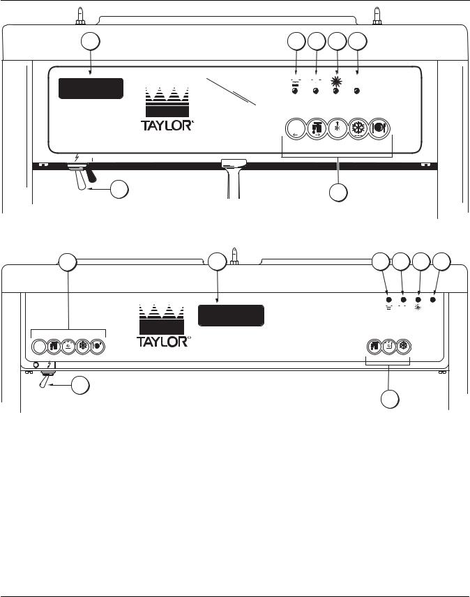
Section 5 |
Important: To the Operator |
|||
PH71 |
|
|
|
|
2 |
3 |
4 |
5 |
6 |
|
|
|
|
|
|
|
|
|
|
|
|
|
|
|
|
|
|
|
|
|
|
|
|
|
|
|
|
|
|
|
|
|
|
|
|
MIX |
MIX |
HEAT |
CLEAN |
||||||||
LOW |
OUT |
MODE |
MANUALLY |
||||||||
|
|
|
|
||||||||
+++
WASH PUMP AUTO MENU
 OFF
OFF  ON
ON
1 |
7 |
|
PH84
7 |
2 |
3 |
4 |
5 |
6 |
|
|
|
|
|
|
|
|
|
|
|
MIX |
|
MIX |
HEAT |
CLEAN |
||||||
LOW |
OUT |
MODE |
MANUALLY |
|||||||
< - - |
- - > |
+ + + |
- - - |
SEL |
|
|
|
|
WASH |
PUMP |
AUTO |
MENU |
WASH |
PUMP |
AUTO |
OFF |
|
ON |
|
|
|
|
|
|
1 |
|
|
ITEM |
DESCRIPTION |
|
|
1 |
POWER SWITCH (TOGGLE) |
2 |
LCD DISPLAY |
|
|
3 |
MIX LOW INDICATOR LIGHT |
|
|
4 |
MIX OUT INDICATOR LIGHT |
|
|
|
7 |
|
|
ITEM |
DESCRIPTION |
|
|
5 |
HEAT MODE INDICATOR LIGHT |
6 |
CLEAN MANUALLY INDICATOR LIGHT |
|
|
7 |
KEYPADS |
|
|
Important: To the Operator |
12 |
Models PH71/PH84 |
|
|
|
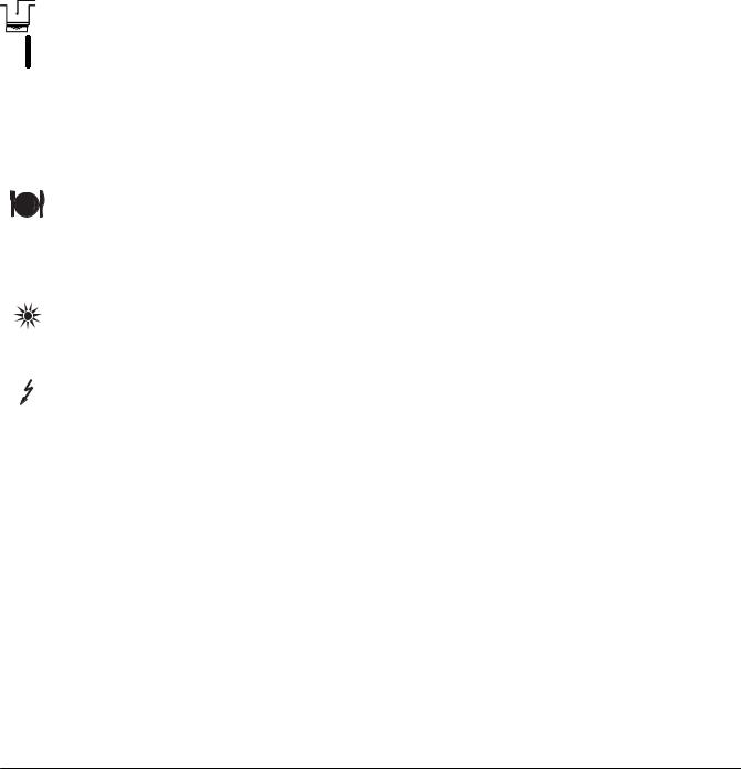
Symbol Definitions
To better communicate in the International arena, the words on many of our operator switches and buttons have symbols to indicate their functions. Your Taylor equipment is designed with these International symbols.
The following chart identifies the symbol definitions used on the operator switches.
= AUTO
= ON
= OFF
= WASH
= PUMP
= MENU
= MIX LOW
= MIX OUT
= HEAT MODE
= CLEAN MANUALLY/BRUSH CLEAN
= POWER
Power Switch
When placed in the ON position, the power switch allows softech control panel operation.
Liquid Crystal Display
The Liquid Crystal Display (LCD) is located on the front control panel. The LCD is used to show the current mode of operation, and whether or not there is sufficient mix.
Indicator Lights
MIX LOW - When the MIX LOW light begins to flash, it indicates the mix hopper has a low supply of mix and should be refilled as soon as possible. On double head units, the word “LOW” will also display on the LCD indicator next to the word “MIX”.
MIX OUT - When the MIX OUT light begins to flash, it indicates the mix hopper has been almost completely exhausted and has an insufficient supply of mix to operate the freezer. At this time, the AUTO mode is locked out and the freezer will be placed in the STANDBY mode. To initiate the refrigeration system, add mix to the mix hopper and press the AUTO key. The freezer will automatically begin operation.
HEAT MODE - When the HEAT MODE light is flashing, it indicates that the freezer is in the process of a heat cycle.
CLEAN MANUALLY - When the CLEAN MANUALLY light is flashing, it indicates that the machine must be disassembled and brush cleaned within 24 hours.
When the MIX LOW, MIX OUT, HEAT MODE, and CLEAN MANUALLY indicator lights are all flashing, this signifies a locked condition.
Reset Mechanism
The reset button is located in the service panel. The Model PH84 has two reset mechanisms, one for each side of the freezer.
The reset mechanism protects the beater motor from an overload condition. Should an overload occur, the reset mechanism will trip. To properly reset the freezer place the power switch in the OFF position. Press the reset button firmly. Turn the power switch to the ON position. Clear the fault. Press the WASH key and observe the freezer’s performance. Open the side access panel to check if the beater motor is turning the drive shaft in a clockwise (from operator end) direction without binding.
 Warning: Do not use metal objects to press the reset button. Failure to comply may result in severe personal injury or death.
If it is turning properly, press the WASH key to cancel cycle. Press the AUTO key on both sides of the machine to resume normal operation. If the freezer shuts down again, contact your authorized service technician.
Models PH71/PH84 |
13 |
Important: To the Operator |
|
|
|

Air/Mix Pump Reset Mechanism
The reset button for the pump is located in the service panel. The reset protects the pump from an overload condition. Should an overload occur, the reset mechanism will trip. To reset the pump, press the reset button firmly. The Model PH84 has two pump reset mechanisms, one for each side of the freezer.
 Warning: Do not use metal objects to press the reset button. Failure to comply may result in severe personal injury or death.
Adjustable Draw Handle
This unit features an adjustable draw handle to provide the best portion control, giving a better, consistent quality to your product and controlling costs. The draw handle should be adjusted to provide a flow rate of 5 to 7-1/2 oz. of product by weight per 10 seconds. To INCREASE the flow rate, turn the screw COUNTERCLOCKWISE, and CLOCKWISE to DECREASE the flow rate. In addition, for purposes of SANITIZING and RINSING, the flow rate can be increased by removing the pivot pin and placing the restrictive bar on the TOP. When drawing product, always have the restrictive bar on the BOTTOM.
IMPORTANT: Once the draw rate is set, tighten the lock nut with a wrench.
Operating Screen Descriptions
When the machine is powered the system will initialize. The screen will display “INITIALIZING”. There will be four types of data the system will check: LANGUAGE, SYSTEM DATA, CONFIG DATA, and LOCKOUT DATA. During the INITIALIZING... LANGUAGE screen, the alarm will be on. If the system data, configuration data, or lockout history data has become corrupt, the following screen will alert the operator that the system settings may have been changed.
NVRAM FAULT
RESET TO DEFAULTS
PRESS SEL KEY
Once the system has initialized the SAFETY TIMEOUT screen is displayed and the alarm is turned on.
SAFETY TIMEOUT
ANY KEY ABORTS
This screen will be displayed, with the alarm on, for 60 seconds or until any key is pressed.
After the safety timeout has been completed, and the power switch is OFF, one of the following screens is displayed.
The first screen is displayed if the machine is not in a brush clean state. If any of the requirements for a brush clean have not been met, the time displayed will remain at 5:00 minutes.
PH71 Screen:
POWER SWITCH OFF
TIME: 4:40
HOPPER: 62.1
BARREL: 67.7
PH84 Screen:
|
POWER SWITCH OFF |
|
OUT |
TIME: 4:40 |
OUT |
68.5 |
HOPPER |
62.1 |
69.5 |
BARREL |
67.7 |
When all the requirements for a brush cleaning are met, and the five minutes expire, the screen will change to the second screen, which is the standard power switch OFF screen.
POWER SWITCH OFF
-= - = - = - = - = - UNIT CLEANED
When the power switch is set in the ON position, the system mode of operation screen is displayed. In this example, the machine is ON, but no mode of operation has been selected. The second line of the display indicates whether there is a sufficient supply of mix in the hopper or if there is a LOW or OUT mix condition
Important: To the Operator |
14 |
Models PH71/PH84 |
|
|
|

(PH84 only). The third line of the display shows the temperature of the mix hopper. After pressing the AUTO key, the last line of the display shows the month and date (MM = month, DD = day) that the machine needs to be disassembled and brush cleaned.
PH71 Screen:
MODE: OFF
HOPPER TEMP: 40.0F
BRUSH CLEAN ON: MM/DD
PH84 Screen:
OFF |
:MODE: |
OFF |
OK |
:MIX: |
OK |
40.0F |
HOPPER |
40.0F |
BRUSH CLEAN ON: |
MM/DD |
|
|
|
|
The next display indicates the freezer is operating in two different modes. The following information is given:
The machine is operating in the WASH and PUMP modes, the temperature of the mix hopper is 40_F (4.4_C), and the machine needs to be brush cleaned on October 31st.
PH71 Screen:
MODE: WSH-PMP
HOPPER TEMP: 40.0 F
BRUSH CLEAN ON: 10/31
PH84 Screen:
The next display indicates the freezer is operating in 3 different modes. The following information is given:
The left side of the freezer is operating in the STANDBY mode, and the mix level in the hopper is OUT. The right side is operating in the WASH and PUMP modes, and the mix level in the hopper is LOW. The temperature of the mix in both hoppers is 40_F. (4.4_C.), and the machine needs to be brush cleaned on October 31st.
STANDBY |
:MODE: |
WSH-PMP |
OUT |
:MIX: |
LOW |
40.0F |
HOPPER |
40.0F |
BRUSH CLEAN ON: |
10/31 |
|
The following displays pertain to the HEAT cycle:
While in the heating phase, you will see this display. It shows the present temperature of the hopper.
PH71 Screen:
MODE: HEAT
PHASE: HEAT
HOPPER TEMP: 140.0 F
BRUSH CLEAN ON: MM/DD
PH84 Screen:
HEAT |
:MODE: |
HEAT |
HEAT |
:PHASE: |
HEAT |
140.0F |
HOPPER |
140.0F |
BRUSH CLEAN ON: |
MM/DD |
|
The mix temperature must be raised above 151_F (66.1_C) within 90 minutes or the freezer will be locked in STANDBY, and the cycle failure display will appear.
In the example, the hopper temperature is 140_F (60_C). The phase shows that the machine is in the heat phase of the heat treatment cycle.
When the heating phase is complete, the freezer goes into the holding phase of the cycle. The holding phase will hold the temperature above 151_F (66.1_C) for a minimum of 30 minutes.
In this example, the hopper temperature is 151_F (66.1_C).
PH71 Screen:
MODE: HEAT
PHASE: HOLD
HOPPER TEMP: 151.0 F
BRUSH CLEAN ON: MM/DD
PH84 Screen:
HEAT |
:MODE: |
HEAT |
HOLD |
:PHASE: |
HOLD |
151.0F |
HOPPER |
151.0F |
BRUSH CLEAN ON: |
MM/DD |
|
|
|
|
Models PH71/PH84 |
15 |
Important: To the Operator |
|
|
|

The final phase of the heat treatment cycle is the cooling phase. Now the freezer must cool the mix below 41_F (5_C). If the product fails to cool in two hours, the freezer will lock out.
This example illustrates that the temperature is being lowered, but has not yet reached the set point.
PH71 Screen:
MODE: HEAT
PHASE: COOL
HOPPER TEMP: 55.0 F
BRUSH CLEAN ON: MM/DD
PH84 Screen:
HEAT |
:MODE: |
HEAT |
COOL |
:PHASE: |
COOL |
55.0F |
HOPPER |
55.0F |
BRUSH CLEAN ON: |
MM/DD |
|
The entire heat treatment cycle must be completed in four hours.
When the entire heat cycle has been completed, the normal display will appear, showing the machine in the STANDBY mode. The machine may now be placed in the AUTO mode or left in the STANDBY mode.
PH71 Screen:
MODE: STANDBY
HOPPER TEMP: 41.0 F
BRUSH CLEAN ON: MM/DD
PH84 Screen:
STANDBY |
:MODE: |
STANDBY |
OK |
:MIX: |
OK |
41.0F |
HOPPER |
41.0F |
BRUSH CLEAN ON: |
MM/DD |
|
|
|
|
Hard Lock: There are two causes for a hard lock:
1.Fourteen days have elapsed since the last brush cleaning. The following screen will be displayed.
14 DAY TIMEOUT CLEANING REQ’D FREEZER LOCKED PRESS SEL KEY
2.There has been a thermistor failure (freezing cylinder, hopper, or glycol) during the heat treatment process.
SYSTEM FAULT
SERVICE REQ’D
FREEZER LOCKED
PRESS SEL KEY
All four LED’s on the front of the freezer will light. Press the SEL key.
The next display is the screen which will appear after the failure message. To comply with health codes, heat treatment system freezers must complete a heat treatment cycle daily, and must also be brush cleaned every 14 days. Brush cleaning is the normal disassembly and cleaning procedures. Failure to follow these guidelines will cause the control to lock the freezer out of the AUTO mode. Press the WASH key.
NO AUTO OPERATION
ALLOWED UNTIL
BRUSH CLEANING
PRESS WASH KEY
The next display is the screen which will appear after the brush cleaning message and illustrates that the control is in the OFF mode and the machine needs to be disassembled and brush cleaned.
PH71 Screen:
MODE: OFF
HOPPER TEMP: 41.0 F
FREEZER LOCKED
PH84 Screen:
OFF |
:MODE: |
OFF |
OK |
:MIX: |
OK |
41.0F |
HOPPER |
41.0F |
FREEZER LOCKED |
|
|
|
|
|
Important: To the Operator |
16 |
Models PH71/PH84 |
|
|
|
Soft Lock: If a heat treatment cycle has not been initiated within the last 24 hours, all four LED’s on the front of the machine will light and a message will appear on the LCD. Line 3 of the LCD will indicate the reason the message appears. Following are the variable messages which will appear on line 3:
1.POWER SWITCH OFF: Power switch was in the OFF position.
2.MIX OUT PRESENT: There was mix out condition present.
3.AUTO OR STANDBY OFF: The unit was not in the AUTO or STANDBY mode.
4.NO HEAT CYCLE TRIED: A heat treatment cycle was not attempted in the last 24 hours. (AUTO HEAT TIME was advanced, or a power loss was experienced at the time the cycle was to occur, or a heat cycle failure not due to a thermistor failure.)
NO HEAT TREAT START
BECAUSE
VARIABLE MESSAGE
PRESS SEL KEY
If the following screen appears, a soft lock has occurred during the heat treatment cycle.
HEAT TREAT CYCLE
FAILURE
FREEZER LOCKED
PRESS SEL KEY
If the temperature of the product has not fallen below 41_F (5_C) by the end of the COOL cycle, the following screen will appear.
PRODUCT OVER TEMP
FREEZER LOCKED
PRESS SEL KEY
Press the SEL key to advance to the next display.
When one of these messages appears, automatic freezer operation cannot take place until the freezer is disassembled and brush cleaned or has completed a heat treatment cycle. The next display will instruct the operator to start a heat treatment cycle manually (by
pressing the AUTO key), or to disassemble and brush clean the freezer. If the AUTO key is pressed, the freezer will automatically start the heat treatment cycle and only the heat cycle LED will light.
NO AUTO OPERATION
ALLOWED. PRESS
AUTO FOR HEAT CYCLE
WASH TO BRUSH CLEAN
If the WASH key is pressed, the next display will appear and the freezer will have to be disassembled and brush cleaned.
PH71 Screen:
MODE: OFF
HOPPER TEMP: 41.0F
FREEZER LOCKED
PH84 Screen:
OFF |
:MODE: |
OFF |
OK |
:MIX: |
OK |
41.0F |
HOPPER |
41.0F |
FREEZER LOCKED |
|
|
Once the freezer is unlocked by starting a heat treatment cycle, only the heat cycle LED will light. If the freezer is unlocked by brush cleaning, the mix low and mix out LED’s will light.
Operator Menu
The OPERATOR MENU is used to enter the operator function displays. To access the OPERATOR MENU, simply press the MENU key. The cursor will flash under the letter “A” indicating that this is screen “A”. To select a different screen, use the arrow keys and move the cursor to the desired screen selection and press the SEL key.
OPERATOR MENU |
|
A B C D E F G H I J |
|
EXIT FROM MENU |
|
<- - - - - -> |
SEL |
|
|
Models PH71/PH84 |
17 |
Important: To the Operator |
|
|
|

Screen “B” is FAULT DESCRIPTION. The fault description will indicate if there is a fault with the freezer and the side of the freezer where the fault occurred. To clear the tone for any faults which have been corrected, press the left arrow key. To see if there is more than one fault per cylinder, press the SEL key. When the last fault is displayed, the control will return to the OPERATOR MENU. To return to the main screen, move the cursor to “A” and press the SEL key again.
Listed below are the variable messages which will appear, along with the corrective action:
1.NO FAULT FOUND: There was no fault found in the freezer. Nothing will appear on the screen after this variable message appears.
2.BEATER OVERLOAD: Press the reset button firmly. Clear the tone.
3.HPCO COMPRESSOR: Place the power switch in the OFF position. Wait 5 minutes for the machine to cool. Place the power switch in the ON position. Clear the tone.
4.COMP ON TOO LONG: Place the power switch in the OFF position. Call a service technician. Clear the tone.
5.HOPPER THERM BAD: Place the power switch in the OFF position. Call a service technician.
6.BARREL THERM BAD: Place the power switch in the OFF position. Call a service technician.
7.GLYCOL THERM BAD: Place the power switch in the OFF position. Call a service technician.
8.HOPPER OVER TEMP: The hopper temperature has risen too high as follows. Clear the tone.
a.The hopper temperature reaches 41_F. (5_C.) or higher after a power failure.
b.The hopper temperature has not fallen below 41_F. (5_C.) by the end of the COOL phase in the heat cycle.
9.BARREL OVER TEMP: The barrel (freezing cylinder) temperature has risen too high as follows. Clear the tone.
a.The barrel (freezing cylinder) temperature reaches 41_F. (5_C.) or higher after a power failure.
b.The barrel (freezing cylinder) temperature has not fallen below 41_F. (5_C.) by the end of the COOL phase in the heat cycle.
10.POWER FAILURE: This message will appear in the FAULT DESCRIPTION if a power failure has occurred. Clear the tone.
PH71 Screen:
FAULT DESCRIPTION |
|
VARIABLE MESSAGE |
|
CLR |
SEL |
PH84 Screen:
FAULT DESCRIPTION |
|
L: VARIABLE MESSAGE |
|
R: VARIABLE MESSAGE |
|
CLR |
SEL |
Screen “C” is SET CLOCK. This screen will display the current date and time. The date and time may be changed only after the freezer has been manually brush cleaned, but before it has been placed in the AUTO mode. Move the cursor under the number you wish to change. Press the plus key to increase the number; press the minus key to decrease the number. When the desired time and date appears, press the SEL key once to return to the OPERATOR MENU.
SET CLOCK |
|
|
|
10:21 AM |
06/07/2001 |
|
|
- - |
|
|
|
<- - - - - -> |
+++ |
- - - |
SEL |
If an illegal date is entered, the following screen will appear. The correct date must be entered before leaving this display.
SET CLOCK |
|
|
|
10:34 AM |
02/30/2001 |
|
|
- - |
INVALID DATE |
|
|
<- - - - - -> |
+++ |
- - - |
SEL |
|
|
|
|
Important: To the Operator |
18 |
Models PH71/PH84 |
|
|
|

Screen “D” is SYSTEM INFORMATION. The first screen indicates the software version used in the unit.
SOFTWARE VERSION
PH71 Control UVC2
Version 2.00
SEL
Press the SEL key to view the second screen of the SYSTEM INFORMATION display. This screen indicates the language, version number and language strings used in the unit.
Language |
|
V1.10r00 |
English 459 |
SEL
Press the SEL key to view the third screen of the SYSTEM INFORMATION display. This screen indicates the Bill of Material number and serial number of the unit. Press the SEL key once to return to the OPERATOR MENU.
B.O.M. |
PH7133B000 |
S/N |
K0000000 |
SEL
Screen “E” is AUTO HEAT TIME. This screen is used to set the time of day in which the heat treatment cycle will start. Move the cursor under the number you wish to change. Press the plus key to increase the number; press the minus key to decrease the number. When the desired time appears, press the SEL key once to return to the OPERATOR MENU.
AUTO HEAT TIME |
|
|
|
TIME: 12:00 AM |
|
|
|
- - |
|
|
|
<- - - - - -> |
+++ |
- - - |
SEL |
Screen “F” is CURRENT CONDITIONS. This screen gives the viscosity of the product and the hopper and barrel temperatures. The last line of the display is the compressor countdown safety timer. The safety timer prevents the compressor from running more than 11 minutes (other than during the cooling phase of the heat treatment cycle).
Press the SEL key once to view the SERVINGS COUNTER screen.
PH71 Screen:
VISC |
HOPPER |
BARREL |
0 |
38.5 |
28.5 |
TIME C |
11:00 |
11:00 |
PH84 Screen:
VISC |
HOPPER |
BARREL |
0 |
38.5 |
28.5 |
0.0 |
38.5 |
18.0 |
TIME C |
11:00 |
11:00 |
The SERVINGS COUNTER screen indicates the number of times the draw switch has closed (number of draws) since the last brush cleaning or since the last serving counter reset. A maximum of 32,767 draws can be recorded; an additional draw will cause the counter to restart at zero. Pressing the SEL key will return the display to the OPERATUR MENU.
PH71 Screen:
SERVINGS COUNTER DRAWS
12
SEL
PH84 Screen:
SERVINGS COUNTER
LEFT |
RIGHT |
12 |
15 |
|
SEL |
Draws are counted during the AUTO mode of operation only.
Screen “G” is HEAT CYCLE DATA. The information from the previous heat treatment cycles can be obtained through this screen. The most recent heat treatment cycle data will be shown first; press the plus key to scroll through the remaining heat cycle displays. If a heat treatment cycle failure should occur, a 2 character message will appear on the second line of the screen. Press the SEL key once to return to the OPERATOR MENU.
Models PH71/PH84 |
19 |
Important: To the Operator |
|
|
|
 Loading...