


OPERATOR'S
MANUAL
Model C606
Combination Freezer
Original Operating Instructions
059714-M
May, 2004 (Original Publication)
(Updated 9/2/14)

Complete this page for quick reference when service is required:
Taylor Distributor:
Address:
Phone:
Service:
Parts:
Date of Installation:
Information found on the data label:
Model Number:
Serial Number:
Electrical Specs: Voltage |
|
Cycle |
|||||
Phase |
|
|
|
|
|
||
Maximum Fuse Size: |
|
|
|
|
A |
||
Minimum Wire Ampacity: |
|
|
|
|
A |
||
E 2004 Carrier Commercial Refrigeration, Inc. 059714-M
Any unauthorized reproduction, disclosure, or distribution of copies by any person of any portion of this work may be a violation of Copyright Law of the United States of America and other countries, could result in the awarding of Statutory Damages of up to $250,000 (17 USC 504) for infringement, and may result in further civil and criminal penalties. All rights reserved.
Taylor Company
a division of Carrier Commercial Refrigeration, Inc. 750 N. Blackhawk Blvd.
Rockton, IL 61072

Table of Contents
Section 1 |
To the Installer . . . . . . . . . . . . . . . . . . . . . . . . . . . . . . . . . . . . . . . . . . . . |
1 |
Installer Safety . . . . . . . . . . . . . . . . . . . . . . . . . . . . . . . . . . . . . . . . . . . . . . . . . . . . . . . . |
1 |
|
Site Preparation . . . . . . . . . . . . . . . . . . . . . . . . . . . . . . . . . . . . . . . . . . . . . . . . . . . . . . . |
1 |
|
Air Cooled Units . . . . . . . . . . . . . . . . . . . . . . . . . . . . . . . . . . . . . . . . . . . . . . . . . . . . . . . |
1 |
|
Electrical Connections . . . . . . . . . . . . . . . . . . . . . . . . . . . . . . . . . . . . . . . . . . . . . . . . . |
2 |
|
Beater Rotation . . . . . . . . . . . . . . . . . . . . . . . . . . . . . . . . . . . . . . . . . . . . . . . . . . . . . . . |
2 |
|
Refrigerant |
. . . . . . . . . . . . . . . . . . . . . . . . . . . . . . . . . . . . . . . . . . . . . . . . . . . . . . . . . . . |
3 |
Section 2 |
To the Operator . . . . . . . . . . . . . . . . . . . . . . . . . . . . . . . . . . . . . . . . . . . |
4 |
Section 3 |
Safety . . . . . . . . . . . . . . . . . . . . . . . . . . . . . . . . . . . . . . . . . . . . . . . . . . . . |
6 |
Section 4 |
Operator Parts Identification . . . . . . . . . . . . . . . . . . . . . . . . . . . . . . . |
8 |
Exploded View . . . . . . . . . . . . . . . . . . . . . . . . . . . . . . . . . . . . . . . . . . . . . . . . . . . . . . . . |
8 |
|
Front View |
. . . . . . . . . . . . . . . . . . . . . . . . . . . . . . . . . . . . . . . . . . . . . . . . . . . . . . . . . . . |
10 |
Syrup Cabinet View . . . . . . . . . . . . . . . . . . . . . . . . . . . . . . . . . . . . . . . . . . . . . . . . . . . |
12 |
|
Syrup Pump & Tubes . . . . . . . . . . . . . . . . . . . . . . . . . . . . . . . . . . . . . . . . . . . . . . . . . . |
13 |
|
X57028-XX Pump A. - Mix Simplified - Shake . . . . . . . . . . . . . . . . . . . . . . . . . . . . . |
14 |
|
X57029-XX Pump A. - Mix Simplified - Soft Serve . . . . . . . . . . . . . . . . . . . . . . . . . |
15 |
|
X59304 Syrup Line Assembly - Thin Viscosity Syrup . . . . . . . . . . . . . . . . . . . . . . . |
16 |
|
X56652 Syrup Line Assembly - Thick Viscosity Shake Syrup (Optional) . . . . . . |
17 |
|
X58450 Syrup Line Assembly - Syrup-In-Bag Option . . . . . . . . . . . . . . . . . . . . . . . |
18 |
|
Mix Hopper - Top View . . . . . . . . . . . . . . . . . . . . . . . . . . . . . . . . . . . . . . . . . . . . . . . . . |
19 |
|
Accessories |
. . . . . . . . . . . . . . . . . . . . . . . . . . . . . . . . . . . . . . . . . . . . . . . . . . . . . . . . . . |
20 |
X44127 Brush Kit Assembly . . . . . . . . . . . . . . . . . . . . . . . . . . . . . . . . . . . . . . . . . . . . |
22 |
|
X53800-BRN/TAN Syrup Pump . . . . . . . . . . . . . . . . . . . . . . . . . . . . . . . . . . . . . . . . . |
23 |
|
Beater Door Assembly - Shake Side . . . . . . . . . . . . . . . . . . . . . . . . . . . . . . . . . . . . . |
24 |
|
Beater Door Assembly - Soft Serve Side . . . . . . . . . . . . . . . . . . . . . . . . . . . . . . . . . |
26 |
|
059088 Tray-Parts-Shake Side . . . . . . . . . . . . . . . . . . . . . . . . . . . . . . . . . . . . . . . . . |
27 |
|
059087 Tray-Parts-Soft Serve Side . . . . . . . . . . . . . . . . . . . . . . . . . . . . . . . . . . . . . . |
28 |
|
056525 Tray-Parts-Pump-Simplified . . . . . . . . . . . . . . . . . . . . . . . . . . . . . . . . . . . . . |
29 |
|
Section 5 |
Important: To the Operator . . . . . . . . . . . . . . . . . . . . . . . . . . . . . . . . . |
30 |
Symbol Definitions . . . . . . . . . . . . . . . . . . . . . . . . . . . . . . . . . . . . . . . . . . . . . . . . . . . . |
31 |
|
Power Switch . . . . . . . . . . . . . . . . . . . . . . . . . . . . . . . . . . . . . . . . . . . . . . . . . . . . . . . . . |
31 |
|
Vacuum Fluorescent Display . . . . . . . . . . . . . . . . . . . . . . . . . . . . . . . . . . . . . . . . . . . |
31 |
|
Model C606 |
Table of Contents |
|
|

|
|
Table of Contents - Page 2 |
Indicator Lights . . . . . . . . . . . . . . . . . . . . . . . . . . . . . . . |
. . . . . . . . . . . . . . . . . . . . . . . . 31 |
|
Heat Mode Symbol . . . . . . . . . . . . . . . . . . . . . . . . . . . . . |
. . . . . . . . . . . . . . . . . . . . . . . 32 |
|
Reset Mechanism . . . . . . . . . . . . . . . . . . . . . . . . . . . . . . |
. . . . . . . . . . . . . . . . . . . . . . . 32 |
|
Air/Mix Pump Reset Mechanism . . . . . . . . . . . . . . . . . |
. . . . . . . . . . . . . . . . . . . . . . . 32 |
|
Adjustable Draw Handle . . . . . . . . . . . . . . . . . . . . . . . . |
. . . . . . . . . . . . . . . . . . . . . . . 32 |
|
Shake Fill Level Adjustment . . . . . . . . . . . . . . . . . . . . . |
. . . . . . . . . . . . . . . . . . . . . . . 33 |
|
VFD Screens . . . . . . . . . . . . . . . . . . . . . . . . . . . . . . . . . . |
. . . . . . . . . . . . . . . . . . . . . . . 33 |
|
Manager's Menu . . . . . . . . . . . . . . . . . . . . . . . . . . . . . . . |
. . . . . . . . . . . . . . . . . . . . . . . 38 |
|
Section 6 |
Operating Procedures . . . . . . . . . . . . . . |
. . . . . . . . . . . . . . . . . . . . . . . 52 |
Equipment Set-Up . . . . . . . . . . . . . . . . . . . . . . . . . . . . . . |
. . . . . . . . . . . . . . . . . . . . . . . 52 |
|
Freezing Cylinder Assembly - Shake Side . . . . . . . . . |
. . . . . . . . . . . . . . . . . . . . . . . 52 |
|
Freezing Cylinder Assembly - Soft Serve Side . . . . . |
. . . . . . . . . . . . . . . . . . . . . . . 56 |
|
Mix Pump Assembly . . . . . . . . . . . . . . . . . . . . . . . . . . . . |
. . . . . . . . . . . . . . . . . . . . . . . 60 |
|
Sanitizing - Shake Side . . . . . . . . . . . . . . . . . . . . . . . . . |
. . . . . . . . . . . . . . . . . . . . . . . 63 |
|
Sanitizing - Soft Serve Side . . . . . . . . . . . . . . . . . . . . . . |
. . . . . . . . . . . . . . . . . . . . . . . 66 |
|
Priming - Shake Side . . . . . . . . . . . . . . . . . . . . . . . . . . . |
. . . . . . . . . . . . . . . . . . . . . . . 67 |
|
Priming - Soft Serve Side . . . . . . . . . . . . . . . . . . . . . . . |
. . . . . . . . . . . . . . . . . . . . . . . 68 |
|
Daily Closing Procedures . . . . . . . . . . . . . . . . . . . . . . . |
. . . . . . . . . . . . . . . . . . . . . . . 68 |
|
Daily Opening Procedures . . . . . . . . . . . . . . . . . . . . . . . |
. . . . . . . . . . . . . . . . . . . . . . . 73 |
|
Syrup System . . . . . . . . . . . . . . . . . . . . . . . . . . . . . . . . . . |
. . . . . . . . . . . . . . . . . . . . . . . 78 |
|
Syrup Topping Pump . . . . . . . . . . . . . . . . . . . . . . . . . . . |
. . . . . . . . . . . . . . . . . . . . . . . 81 |
|
Manual Brush Cleaning . . . . . . . . . . . . . . . . . . . . . . . . . |
. . . . . . . . . . . . . . . . . . . . . . . 87 |
|
Draining Product From The Freezing Cylinder . . . . . |
. . . . . . . . . . . . . . . . . . . . . . . 88 |
|
Rinsing . . . |
. . . . . . . . . . . . . . . . . . . . . . . . . . . . . . . . . . . . |
. . . . . . . . . . . . . . . . . . . . . . . 89 |
Cleaning and Sanitizing . . . . . . . . . . . . . . . . . . . . . . . . . |
. . . . . . . . . . . . . . . . . . . . . . . 89 |
|
Disassembly - Shake Side . . . . . . . . . . . . . . . . . . . . . . . |
. . . . . . . . . . . . . . . . . . . . . . . 90 |
|
Disassembly - Soft Serve Side . . . . . . . . . . . . . . . . . . . |
. . . . . . . . . . . . . . . . . . . . . . . 91 |
|
Brush Cleaning . . . . . . . . . . . . . . . . . . . . . . . . . . . . . . . . |
. . . . . . . . . . . . . . . . . . . . . . . 92 |
|
Syrup System - Scheduled Maintenance . . . . . . . . . . |
. . . . . . . . . . . . . . . . . . . . . . . 93 |
|
Section 7 |
Important: Operator Checklist . . . . . . . |
. . . . . . . . . . . . . . . . . . . . . . . 97 |
During Cleaning and Sanitizing . . . . . . . . . . . . . . . . . . |
. . . . . . . . . . . . . . . . . . . . . . . 97 |
|
Troubleshooting Bacterial Count . . . . . . . . . . . . . . . . . |
. . . . . . . . . . . . . . . . . . . . . . . 97 |
|
Regular Maintenance Checks . . . . . . . . . . . . . . . . . . . . |
. . . . . . . . . . . . . . . . . . . . . . . 97 |
|
Winter Storage . . . . . . . . . . . . . . . . . . . . . . . . . . . . . . . . . |
. . . . . . . . . . . . . . . . . . . . . . . 98 |
|
Table of Contents |
Model C606 |
|
|

|
|
Table of Contents - Page 3 |
Section 8 |
Troubleshooting Guide . . . . . . . . . . . . |
. . . . . . . . . . . . . . . . . . . . . . . . 99 |
Section 9 |
Parts Replacement Schedule . . . . . . . . |
. . . . . . . . . . . . . . . . . . . . . . . 111 |
Section 10 |
Limited Warranty on Equipment . . . . . |
. . . . . . . . . . . . . . . . . . . . . . . 112 |
Section 11 |
Limited Warranty on Parts . . . . . . . . . . |
. . . . . . . . . . . . . . . . . . . . . . . 114 |
Wiring Diagrams . . . . . . . . . . . . . . . . . . . . . . . . . . . . . . . |
. . . . . . . . . . . . . . . . . . . . . . . 117 |
|
Note: Continuing research results in steady improvements; therefore, information in this manual is subject to change without notice.
Note: Only instructions originating from the factory or its authorized translation representative(s) are considered to be the original set of instructions.
E 2004 Carrier Commercial Refrigeration, Inc. (Original Publication) (Updated September, 2014)
059714-M
Any unauthorized reproduction, disclosure, or distribution of copies by any person of any portion of this work may be a violation of Copyright Law of the United States of America and other countries, could result in the awarding of Statutory Damages of up to $250,000 (17 USC 504) for infringement, and may result in further civil and criminal penalties. All rights reserved.
Taylor Company
a division of Carrier Commercial Refrigeration, Inc. 750 N. Blackhawk Blvd.
Rockton, IL 61072
Model C606 |
Table of Contents |
|
|

Notes:
Table of Contents |
Model C606 |
|
|

Section 1 |
To the Installer |
The following information has been included in the manual as safety and regulatory guidelines. For complete installation instructions, please see the Installation Checklist.
Installer Safety
 In all areas of the world, equipment should be installed in accordance with existing local codes. Please contact your local authorities if you have any questions.
Care should be taken to ensure that all basic safety practices are followed during the installation and servicing activities related to the installation and service of Taylor equipment.
SOnly authorized Taylor service personnel should perform installation and repairs on the equipment.
SAuthorized service personnel should consult OSHA Standard 29CFRI910.147 or the applicable code of the local area for the industry standards on lockout/tagout procedures before beginning any installation or repairs.
SAuthorized service personnel must ensure that the proper PPE is available and worn when required during installation and service.
SAuthorized service personnel must remove all metal jewelry, rings, and watches before working on electrical equipment.
 The main power supply(s) to the freezer must be disconnected prior to performing any repairs. Failure to follow this instruction may result in personal injury or death from electrical shock or hazardous moving parts as well as poor performance or damage to the equipment.
Note: All repairs must be performed by an authorized Taylor Service Technician.
 This unit has many sharp edges that can cause severe injuries.
Site Preparation
Review the area where the unit will be installed before uncrating the unit. Make sure that all possible hazards to the user and the equipment have been addressed.
Air Cooled Units
DO NOT obstruct air intake and discharge openings:
Air cooled units require a minimum of 3” (76 mm) of clearance around all sides of the freezer to allow for adequate air flow across the condensers. Install the deflector provided to prevent recirculation of warm air. Failure to allow adequate clearance can reduce the refrigeration capacity of the freezer and possibly cause permanent damage to the compressors.
For Indoor Use Only: This unit is designed to operate indoors, under normal ambient temperatures of 70_-75_F (21_-24_C). The freezer has successfully performed in high ambient temperatures of 104_(40_C) at reduced capacities.
 This unit must NOT be installed in an area where a water jet or hose can be used. NEVER use a water jet or hose to rinse or clean the unit. Failure to follow this instruction may result in electrocution.
 This unit must be installed on a level surface to avoid the hazard of tipping. Extreme care should be taken in moving this equipment for any reason. Two or more persons are required to safely move this unit. Failure to comply may result in personal injury or equipment damage.
Uncrate the unit and inspect it for damage. Report any damage to your Taylor Distributor.
This piece of equipment is made in the USA and has USA sizes of hardware. All metric conversions are approximate and vary in size.
131125
Model C606 |
1 |
To the Installer |
|
|
|
Electrical Connections
In the United States, this equipment is intended to be installed in accordance with the National Electrical Code (NEC), ANSI/NFPA 70-1987. The purpose of the NEC code is the practical safeguarding of persons and property from hazards arising from the use of electricity. This code contains provisions considered necessary for safety. In all other areas of the world, equipment should be installed in accordance with the existing local codes. Please contact your local authorities.
FOLLOW YOUR LOCAL ELECTRICAL CODES!
Each unit requires one power supply for each data label on the unit. Check the data label(s) on the freezer for branch circuit overcurrent protection or fuse, circuit ampacity and other electrical specifications. Refer to the wiring diagram provided inside of the electrical box, for proper power connections.
 CAUTION: THIS EQUIPMENT MUST BE PROPERLY GROUNDED! FAILURE TO DO SO CAN RESULT IN SEVERE PERSONAL INJURY FROM ELECTRICAL SHOCK!
 DO NOT operate this freezer with larger fuses than specified on the unit data label. Failure to follow this instruction may result in electrocution or damage to the machine.
 This unit is provided with an equipotential grounding lug that is to be properly attached to the rear of the frame by the authorized installer. The installation location is marked by the equipotential bonding symbol (5021 of IEC 60417-1) on both the removable panel and the equipment's frame.
 Stationary appliances which are not equipped with a power cord and a plug or another device to disconnect the appliance from the power source must have an all-pole disconnecting device
130318
with a contact gap of at least 3 mm installed in the external installation.
 Appliances that are permanently connected to fixed wiring and for which leakage currents may exceed 10 mA, particularly when disconnected or not used for long periods, or during initial installation, shall have protective devices such as a GFI, to protect against the leakage of current, installed by the authorized personnel to the local codes.
 Supply cords used with this unit shall be oil-resistant, sheathed flexible cable not lighter than ordinary polychloroprene or other equivalent synthetic elastomer-sheathed cord (Code designation 60245 IEC 57) installed with the proper cord anchorage to relieve conductors from strain, including twisting, at the terminals and protect the insulation of the conductors from abrasion.
If the supply cord is damaged, it must be replaced by the manufacturer, its service agent, or similarly qualified person, in order to avoid a hazard.
Beater Rotation
 Beater rotation must be clockwise as viewed looking into the freezing cylinder.
Note: The following procedures should be performed by a trained service technician.
To correct the rotation on a three-phase unit, interchange any two incoming power supply lines at freezer main terminal block only.
To correct rotation on a single-phase unit, change the leads inside the beater motor. (Follow the diagram printed on the motor.)
Electrical connections are made directly to the terminal block. The terminal block is provided in the splice box located behind the right side panel.
To the Installer |
2 |
Model C606 |
|
|
|

Refrigerant
 In consideration of our environment, Taylor uses only earth friendly HFC refrigerants. The HFC refrigerant used in this unit is R404A. This refrigerant is generally considered non-toxic and non-flammable, with an Ozone Depleting Potential (ODP) of zero (0).
However, any gas under pressure is potentially hazardous and must be handled with caution.
NEVER fill any refrigerant cylinder completely with liquid. Filling the cylinder to approximately 80% will allow for normal expansion.
 Use only R404A refrigerant that conforms to the AHRI standard 700 specification. The use of any other refrigerant may expose users and operators to unexpected safety hazards.
 Refrigerant liquid sprayed onto the skin may cause serious damage to tissue. Keep eyes and skin protected. If refrigerant burns should occur, flush immediately with cold water. If burns are severe, apply ice packs and contact a physician immediately.
 Taylor reminds technicians to be cautious of government laws regarding refrigerant recovery, recycling, and reclaiming systems. If you have any questions regarding these laws, please contact the factory Service Department.
 WARNING: R404A refrigerant used in conjunction with polyolester oils is extremely moisture absorbent. When opening a refrigeration system, the maximum time the system is open must not exceed 15 minutes. Cap all open tubing to prevent humid air or water from being absorbed by the oil.
130813
Model C606 |
3 |
To the Installer |
|
|
|

Section 2 |
To the Operator |
|
|
The freezer you have purchased has been carefully engineered and manufactured to give you dependable operation. The Taylor freezer, when properly operated and cared for, will produce a consistent quality product. Like all mechanical products, this machine will require cleaning and maintenance. A minimum amount of care and attention is necessary if the operating procedures outlined in this manual are followed closely.
This Operator's Manual should be read before operating or performing any maintenance on your equipment.
Your Taylor freezer will NOT eventually compensate and correct for any errors during the set-up or filling operations. Thus, the initial assembly and priming procedures are of extreme importance. It is strongly recommended that all personnel responsible for the equipment's operation review these procedures in order to be properly trained and to make sure that there is no confusion.
In the event that you should require technical assistance, please contact your local authorized Taylor Distributor.
Note: Your Taylor warranty is valid only if the parts are authorized Taylor parts, purchased from the local authorized Taylor Distributor, and only if all required service work is provided by an authorized Taylor service technician. Taylor reserves the right to deny warranty claims on units or parts if non-Taylor approved parts or incorrect refrigerant were installed in the unit, system modifications were performed beyond factory recommendations, or it is determined that the failure was caused by abuse, misuse, neglect, or failure to follow all operating instructions. For full details of your Taylor Warranty, please see the Limited Warranty section in this manual.
Note: Constant research results in steady improvements; therefore, information in this manual is subject to change without notice.
 If the crossed out wheeled bin symbol is affixed to this product, it signifies that this product is compliant with the EU Directive as well as other
131125
similar legislation in effect after August 13, 2005. Therefore, it must be collected separately after its use is completed, and cannot be disposed as unsorted municipal waste. The user is responsible for returning the product to the appropriate collection facility, as specified by your local code.
For additional information regarding applicable local laws, please contact the municipal facility and/or local distributor.
Compressor Warranty Disclaimer
The refrigeration compressor(s) on this unit are warranted for the term stated in the Limited Warranty section in this manual. However, due to the Montreal Protocol and the U.S. Clean Air Act Amendments of 1990, many new refrigerants are being tested and developed, thus seeking their way into the service industry. Some of these new refrigerants are being advertised as drop-in replacements for numerous applications. It should be noted that in the event of ordinary service to this unit's refrigeration system, only the refrigerant specified on the affixed data label should be used. The unauthorized use of alternate refrigerants will void your Taylor compressor warranty. It is the unit owner's responsibility to make this fact known to any technician he employs.
Some of these new refrigerants are being advertised as “drop-in” replacements for numerous applications. It should be noted that, in the event of ordinary service to this machine’s refrigeration system, only the refrigerant specified on the affixed data label should be used. The unauthorized use of alternate refrigerants will void your compressor warranty. It will be the owner’s responsibility to make this fact know to any technician he employs.
It should also be noted that Taylor does not warrant the refrigerant used in its equipment. For example, if the refrigerant is lost during the course of ordinary service to this machine, Taylor has no obligation to either supply or provide its replacement either at billable or unbillable terms. Taylor does have the obligation to recommend a suitable replacement if the original refrigerant is banned, obsoleted, or no longer available during the five year warranty of the compressor.
To the Operator |
4 |
Model C606 |
|
|
|
Taylor will continue to monitor the industry and test new alternates as they are being developed. Should a new alternate prove, through our testing, that it would be accepted as a drop-in replacement, then the above disclaimer would become null and void.
To find out the current status of an alternate refrigerant as it relates to your compressor warranty, call the local Taylor Distributor or the Taylor factory. Be prepared to provide the Model/Serial Number of the unit in question.
Model C606 |
5 |
To the Operator |
|
|
|

Section 3 |
Safety |
We at Taylor Company are concerned about the safety of the operator when he or she comes in contact with the freezer and its parts. Taylor has gone to extreme efforts to design and manufacture built-in safety features to protect both you and the service technician. As an example, warning labels have been attached to the freezer to further point out safety precautions to the operator.
 IMPORTANT - Failure to adhere to the following safety precautions may result in severe personal injury or death. Failure to comply with these warnings may damage the machine and its components. Component damage will result in part replacement expense and service repair expense.
 DO NOT operate the freezer without reading this Operator Manual. Failure to follow this instruction may result in equipment damage, poor freezer performance, health hazards, or personal injury.
 This appliance is to be used only by trained personnel. It is not intended for use by children or people with reduced physical, sensory, or mental capabilities, or lack of experience and knowledge, unless given supervision or instruction concerning the use of the appliance by a person responsible for their safety. Children should be supervised to ensure that they do not play with the appliance.
 This unit is provided with an equipotential grounding lug that is to be properly attached to the rear of the frame by the authorized installer. The installation location is marked by the equipotential bonding symbol (5021 of IEC 60417-1) on both the removable panel and the equipment's frame.
 DO NOT use a water jet to clean or rinse the freezer. Failure to follow these instructions may result in serious electrical shock.
130318
SDO NOT operate the freezer unless it is properly grounded.
SDO NOT operate the freezer with larger fuses than specified on the freezer data label.
SAll repairs must be performed by an authorized Taylor service technician.
SThe main power supplies to the machine must be disconnected prior to performing any repairs.
SCord Connected Units: Only Taylor authorized service technicians may install a plug on this unit.
SStationary appliances which are not equipped with a power cord and a plug or another device to disconnect the appliance from the power source must have an all-pole disconnecting device with a contact gap of at least 3 mm installed in the external installation.
SAppliances that are permanently connected to fixed wiring and for which leakage currents may exceed 10 mA, particularly when disconnected or not used for long periods, or during initial installation, shall have protective devices such as a GFI, to protect against the leakage of current, installed by the authorized personnel to the local codes.
SSupply cords used with this unit shall be oil-resistant, sheathed flexible cable not lighter than ordinary polychloroprene or other equivalent synthetic elastomer-sheathed cord (Code designation 60245 IEC 57) installed with the proper cord anchorage to relieve conductors from strain, including twisting, at the terminals and protect the insulation of the conductors from abrasion.
If the supply cord is damaged, it must be replaced by the manufacturer, its service agent, or similarly qualified person, in order to avoid a hazard.
Failure to follow these instructions may result in electrocution. Contact your local authorized Taylor Distributor for service.
Safety |
6 |
Model C606 |
|
|
|

SDO NOT allow untrained personnel to operate this machine.
SDO NOT operate the freezer unless all service panels and access doors are restrained with screws.
SDO NOT remove any internal operating parts (example: freezer door, beater, scraper blades, etc.) unless all control switches are in the OFF position.
Failure to follow these instructions may result in severe personal injury from hazardous moving parts.
 This unit has many sharp edges that can cause severe injuries.
SDO NOT put objects or fingers in the door spout. This may contaminate the product and cause severe personal injury from blade contact.
SUSE EXTREME CAUTION when removing the beater asssembly. The scraper blades are very sharp.
SCAUTION-SHARP EDGES: Two people are required to handle the cup/cone dispenser. Protective gloves must be worn and the mounting holes must NOT be used to lift or hold the dispenser. Failure to follow this instruction can result in personal injury to fingers or equipment damage.
 Access to the service area of the unit is restricted to persons having knowledge and practical experience with the appliance, in particular as far as safety and hygiene are concerned.
 This freezer must be placed on a level surface. Failure to comply may result in personal injury or equipment damage.
 Cleaning and sanitizing schedules are governed by your state or local regulatory agencies and must be followed accordingly. Please refer to the cleaning section of this manual for the proper procedure to clean this unit.
 This machine is designed to maintain product temperature under 41°F (5°C). Any product being added to this machine must be below 41°F (5°C). Failure to follow this instruction may result in health hazards and poor freezer performance.
DO NOT obstruct air intake and discharge openings: 3” (76 mm) minimum air space all sides is required. Install the deflector provided to prevent recirculation of warm air. Failure to follow this instruction may cause poor freezer performance and damage to the machine.
For Indoor Use Only: This unit is designed to operate indoors, under normal ambient temperatures of 70_-75_F (21_-24_C). The freezer has successfully performed in high ambient temperatures of 104_(40_C) at reduced capacities.
DO NOT run the machine without product. Failure to follow this instruction can result in damage to the machine.
NOISE LEVEL: Airborne noise emission does not exceed 78 dB(A) when measured at a distance of 1.0 meter from the surface of the machine and at a height of 1.6 meters from the floor.
130318
Model C606 |
7 |
Safety |
|
|
|

Section 4 Operator Parts Identification
Exploded View
Figure 1
140624
Operator Parts Identification |
8 |
Model C606 |
|
|
|

Exploded View (See Figure 1)
ITEM |
DESCRIPTION |
PART NO. |
|
|
|
|
|
1 |
KIT A.-COVER-HOPPER |
X65368-SP |
|
|
|
|
|
1a |
LABEL-CAUTION-AGITATOR |
045191 |
|
|
|
|
|
2 |
AGITATOR A.-MIX HOPPER-20 |
X44797 |
|
|
|
|
|
3 |
PIN-RETAINING HOPPER CVR |
043934 |
|
|
|
|
|
4 |
PAN-DRIP-REAR |
X56003 |
|
|
|
|
|
5 |
PANEL-REAR-UPPER |
066724 |
|
|
|
|
|
6 |
GUIDE A.-DRIP PAN-MIX PUMP |
X48228 |
|
|
|
|
|
7 |
PANEL-REAR-LOWER |
055959 |
|
|
|
|
|
8 |
PAN-DRIP-SIDE |
X56005 |
|
|
|
|
|
9 |
TRIM-CORNER-REAR-R |
056692 |
|
|
|
||
TRIM-CORNER-REAR-L |
056693 |
||
|
|||
|
|
|
|
10 |
CASTER-4" |
044106 |
|
|
|
|
|
11 |
SCREW-1/4-20X3/8 |
011694 |
|
|
|
|
ITEM |
DESCRIPTION |
PART NO. |
|
|
|
12 |
PANEL-SIDE RIGHT |
055950 |
|
|
|
13 |
TRAY-DRIP |
033812 |
|
|
|
14 |
SHIELD-SPLASH |
033813 |
|
|
|
15 |
LID-SYRUP JAR |
042706 |
|
|
|
16 |
JAR-SYRUP*PLASTIC |
036573 |
|
|
|
17 |
JAR-SYRUP*STAINLESS |
036574 |
|
|
|
18 |
LADLE-1 OZ |
033637-1 |
|
|
|
19 |
PAN-DRIP 19-1/2 LONG |
035034 |
|
|
|
20 |
PLATE-DEC |
056131-1 |
|
|
|
21 |
PANEL-SIDE LEFT |
055957 |
|
|
|
22 |
FILTER-AIR-18.00LX13.50HX.70 |
052779-3 |
|
|
|
23 |
CASTER-4" SWV 3/4-10 STEM |
046437 |
|
W/BRAKE |
|
140624
Model C606 |
9 |
Operator Parts Identification |
|
|
|

Front View
Figure 2
140624
Operator Parts Identification |
10 |
Model C606 |
|
|
|

Front View (See Figure 2)
ITEM |
DESCRIPTION |
PART NO. |
|
|
|
|
|
1 |
STUD-NOSE CONE |
055987 |
|
|
|
|
|
2 |
FITTING-PANEL MOUNT QD |
056674 |
|
|
|
|
|
3 |
CLIP-SPRING-CUP HOLDER |
068394 |
|
|
|
|
|
4 |
LINE A.-SYRUP DOOR |
X59304 |
|
|
|
|
|
5 |
SENSOR A.-PYROELECTRIC |
X59268-SER |
|
|
|
|
|
6 |
KIT A.-SYRUP DOOR |
X65932 |
|
|
(MAGNETIC CATCH) |
CONSISTS |
|
|
|
OF: |
|
|
SCREW-6-32X3/8 SLTD |
(4) 002201 |
|
|
|
|
|
|
MAGNET-CATCH ASSY. |
(2) 016121 |
|
|
|
|
|
|
NUT-10-32 FLANGE LOCKNUT |
(4) 020983 |
|
|
|
|
|
|
SCREW-10-32X3/8 SLTD |
(4) 024298 |
|
|
|
|
|
|
HANDLE-DOOR SHORT |
(2) 065933 |
|
|
|
|
|
|
BRACKET-MAGNET DOOR |
(1) 065934 |
|
|
|
|
|
|
FITTING A.-SYRUP JUG 36" |
X53353-BLU |
|
|
|
|
|
7 |
FITTING A.-SYRUP JUG 36" |
X53353-BRN |
|
|
|
||
FITTING A.-SYRUP JUG 36" |
X53353-RED |
||
|
|||
|
|
|
|
|
FITTING A.-SYRUP JUG 36" |
X53353-WHT |
|
|
|
|
|
|
CAP-ULTIMATE SYRUP |
053040-BLU |
|
|
|
|
|
7a |
CAP-ULTIMATE SYRUP |
053040-RED |
|
|
|
||
CAP-ULTIMATE SYRUP |
053040-BRN |
||
|
|||
|
|
|
|
|
CAP-ULTIMATE SYRUP |
053040-WHT |
|
|
|
|
ITEM |
DESCRIPTION |
PART NO. |
|
|
|
7b |
HOSE-BEVERAGE 3/8"ID X 5/8 |
053052-36 |
|
|
|
7c |
TUBE A.-SYRUP PICK UP |
X53175 |
|
|
|
*7d |
FERRULE-.625 ID NP BRASS |
053036 |
|
|
|
*7e |
FITTING-PERISTALTIC PUMP |
054526 |
|
|
|
*7f |
O-RING-.500 OD X .070W |
024278 |
|
(50 TO BAG) |
|
* |
LINE A.-SYRUP (FOR USE |
X58450 |
|
WITH BAG SYRUP SYSTEM) |
|
8 |
DOOR A.-CABINET |
X58607-SER |
|
|
|
8a |
BASKET-DOOR-WIRE |
059144 |
|
|
|
9 |
HOLDER A.-25DCC PYR SNS |
X69102 |
|
|
|
9a |
SCREW-ADJUSTMENT-5/16-18 |
051574 |
|
|
|
10 |
PUMP A.-SYRUP-HEATED- |
X53800-BRN |
|
BRN |
|
11 |
PUMP A.-SYRUP-HEATED- |
X53800-TAN |
|
TAN |
|
12 |
GASKET-DRIP LIP |
036435 |
|
|
|
*NOT SHOWN
140624
Model C606 |
11 |
Operator Parts Identification |
|
|
|
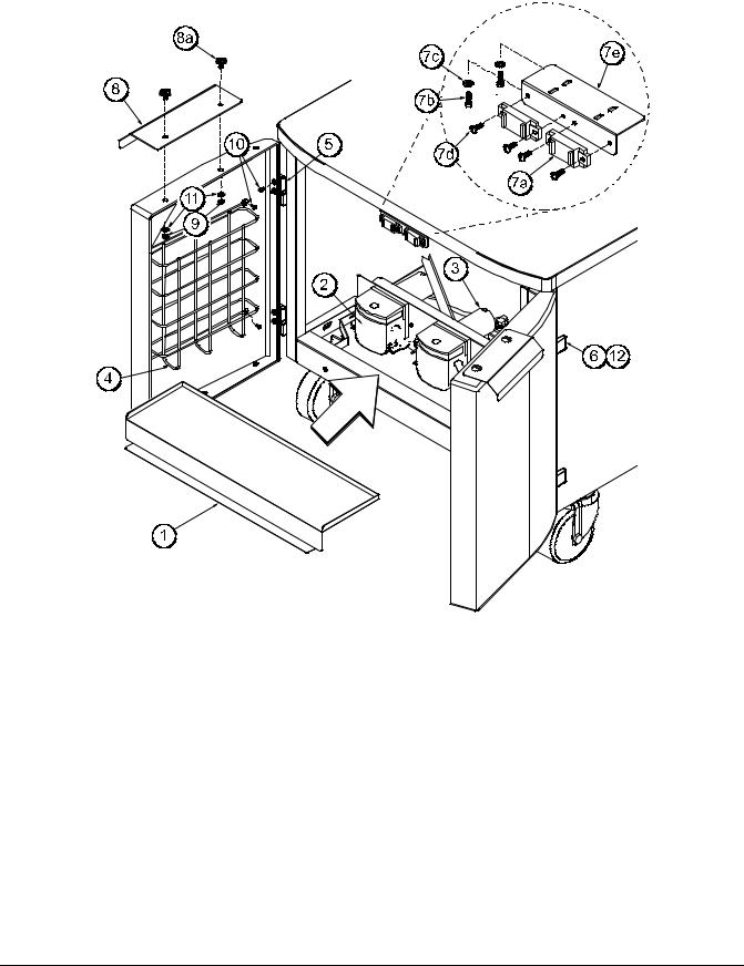
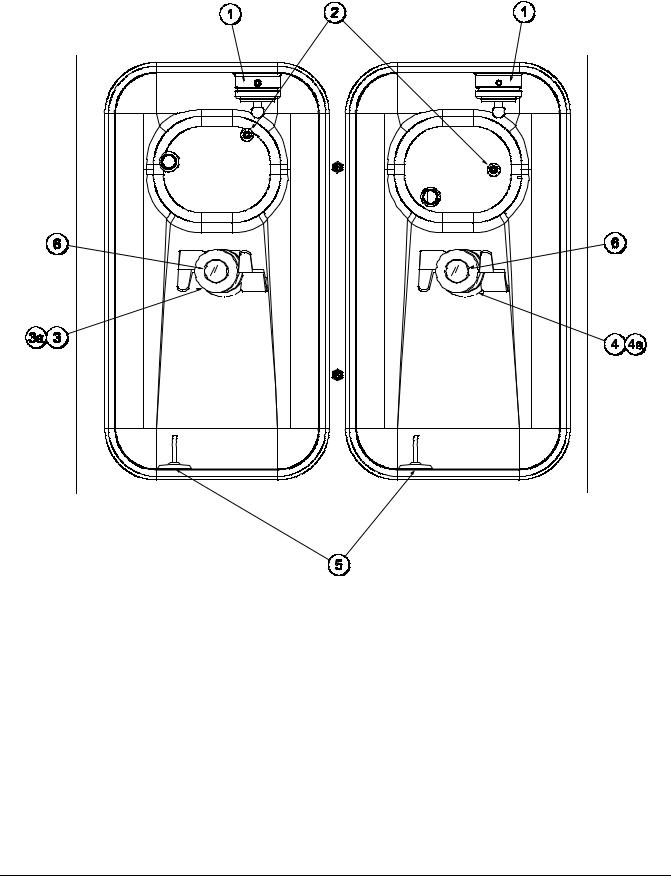
Syrup Cabinet View
Figure 3
ITEM |
DESCRIPTION |
PART NO. |
|
|
|
1 |
SHELF-SYRUP |
056016 |
|
|
|
2 |
PUMP-PERISTALTIC |
052916 |
|
|
|
3 |
MOTOR-GEAR 161 RPM/ |
058725-SER |
|
SHORT SHAFT |
|
4 |
BASKET-DOOR-WIRE |
059144 |
|
|
|
5 |
BLOCK-HINGE |
058613 |
|
|
|
6 |
BLOCK-HINGE |
058614 |
|
|
|
*7a |
MAGNET-CATCH ASSY. |
016121 |
|
|
|
7b |
SCREW-4-40X3/8 SOCKET CAP |
058317 |
|
|
|
140624
ITEM |
DESCRIPTION |
PART NO. |
|
|
|
7c |
WASHER-#4 EXT TOOTH LOCK |
043075 |
|
|
|
7d |
SCREW-6-32X3/8 SLTD BIND |
002201 |
|
|
|
7e |
BRACKET-MAGNET DOOR |
065934 |
|
|
|
8 |
HANDLE-DOOR SHORT |
065933 |
|
|
|
8a |
SCREW-10-32X3/8 SLTD TRUS |
024298 |
|
|
|
9 |
NUT-10-32 FLANGE LOCKNUT |
020983 |
|
|
|
10 |
SCREW-10-32X3/8 SLTD |
006749 |
|
|
|
11 |
WASHER-#8 EXT TOOTH LOCK |
000964 |
|
|
|
12 |
SCREW-8-32X1/4 SLTD ROUND |
016540 |
|
|
|
*PRIOR TO S/N K4091994, USE 058630 LATCH- DOOR-MAGNETIC.
Operator Parts Identification |
12 |
Model C606 |
|
|
|
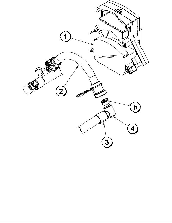
Syrup Pump & Tubes
Figure 4
ITEM |
DESCRIPTION |
PART NO. |
|
|
|
|
|
1 |
PUMP-PERISTALTIC |
052916 |
|
|
|
|
|
|
KIT A.-PERISTALTIC PUMP |
X54978 |
|
2 |
TUBE (1 TUBE KIT) |
|
|
KIT A.-PERISTALTIC PUMP |
X54979 |
||
|
|||
|
TUBE (4 TUBE KIT) |
|
|
|
|
|
ITEM |
DESCRIPTION |
PART NO. |
|
|
|
3 |
FERRULE- .625 ID |
053036 |
|
|
|
4 |
FITTING-PERISTALTIC PUMP |
054526 |
|
|
|
5 |
O-RING 1/2 OD x .070 |
024278 |
|
|
|
*6 |
LINE A.-SYRUP |
X62426-8 |
|
|
|
*NOT SHOWN
Model C606 |
13 |
Operator Parts Identification |
|
|
|
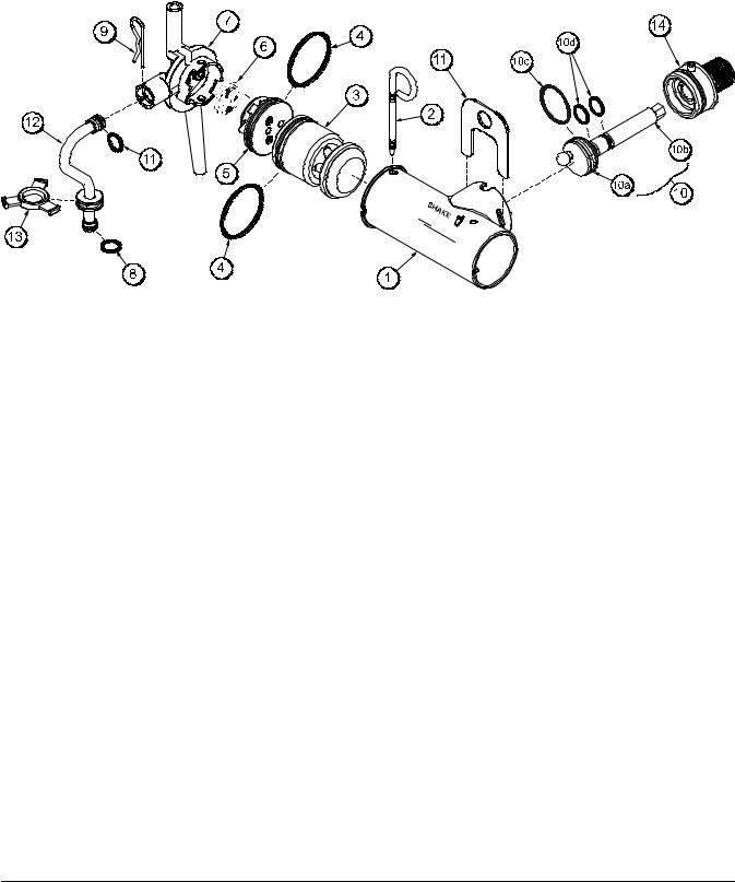
X57028-XX Pump A. - Mix Simplified - Shake
Figure 5
ITEM |
DESCRIPTION |
PART NO. |
|
|
|
1 - 7 |
PUMP ASSEMBLY - MIX |
X57028-10 |
|
SIMPLIFIED SHAKE |
|
1 |
CYLINDER-PUMP HOPPER |
057944 |
|
SHAKE |
|
2 |
PIN-RETAINING |
X55450 |
|
|
|
3 |
PISTON-PUMP-SIMPLIFIED |
053526 |
|
|
|
4 |
O-RING-2-1/8 OD X .139W-#225 |
020051 |
|
|
|
*5 |
CAP-VALVE BODY SHAKE |
056873-10 |
|
|
|
6 |
GASKET - SIMPLIFIED PUMP |
053527 |
|
VALVE |
|
7 |
ADAPTOR - MIX INLET - SHAKE |
054944 |
|
BLUE |
|
8 |
O-RING-11/16ODX.103W-RED |
016132 |
|
(50 TO BAG) |
|
9 |
PIN-COTTER-HAIRPIN-1/8DIA |
044731 |
|
|
|
ITEM |
DESCRIPTION |
PART NO. |
|
|
|
10 |
SHAFT A.-DRIVE-MIX |
X41947 |
|
PUMP-HOPPER |
|
10a |
CRANK-DRIVE-HOPPER MIX |
039235 |
|
PUMP |
|
10b |
SHAFT-DRIVE-MIX PUMP- |
041948 |
|
HOPPER |
|
10c |
O-RING-1-3/4 OD X .139W |
008904 |
|
(25 TO BAG) |
|
10d |
O-RING 1/2 ID X .139W |
048632 |
|
(25 TO BAG) |
|
11 |
CLIP-RETAINER-MIX PUMP |
044641 |
|
|
|
12 |
TUBE A.-FEED TUBE-SHK |
X55973 |
|
|
|
13 |
RING-CHECK-FEED-TUBE |
056524 |
|
|
|
14 |
SLEEVE A.-MIX PUMP |
X44761 |
|
|
|
*STANDARD CAP-VALVE BODY SHAFT IS -10. AVAILABLE IN OTHER SIZES
140624
Operator Parts Identification |
14 |
Model C606 |
|
|
|
X57029-XX Pump A. - Mix Simplified - Soft Serve
Figure 6
ITEM |
DESCRIPTION |
PART NO. |
|
|
|
1 - 7 |
PUMP A.-MIX SIMPLIFIED S.S. |
X57029-12 |
|
|
|
1 |
CYLINDER-PUMP HOPPER |
057943 |
|
SOFTSERVE |
|
2 |
PIN-RETAINING |
X55450 |
|
|
|
3 |
PISTON-PUMP-SIMPLIFIED |
053526 |
|
|
|
4 |
O-RING-2-1/8 OD X .139W-#225 |
020051 |
|
|
|
5 |
CAP-VALVE BODY SS |
056874-12 |
|
|
|
6 |
GASKET-SIMPLIFIED PUMP |
053527 |
|
VALVE |
|
7 |
ADAPTOR-MIX INLET-SS-RED |
054825 |
|
|
|
8 |
O-RING-11/16ODX.103W-RED |
016132 |
|
|
|
9 |
PIN-COTTER-HAIRPIN-1/8DIA |
044731 |
|
|
|
10 |
SHAFT A.-DRIVE-MIX PUMP- |
X41947 |
|
HOPPER |
|
ITEM |
DESCRIPTION |
PART NO. |
|
|
|
10a |
CRANK-DRIVE-HOPPER MIX |
039235 |
|
PUMP |
|
10b |
SHAFT-DRIVE-MIX PUMP- |
041948 |
|
HOPPER |
|
10c |
O-RING-1-3/4 OD X .139W |
008904 |
|
|
|
10d |
O-RING 1/2 ID X .139W |
048632 |
|
|
|
11 |
CLIP-RETAINER-MIX PUMP |
044641 |
|
|
|
12 |
TUBE A.-FEED TUBE-SS |
X55974 |
|
|
|
13 |
RING-CHECK-FEED-TUBE |
056524 |
|
|
|
14 |
SLEEVE A.-MIX PUMP *HT |
X44761 |
|
|
|
*NOTE: THE STANDARD PUMP IS X57029-12. OVERRUN CAN BE CHANGED HIGHER OR LOWER BY SUBSTITUTING THE VALVE BODY CAP. THE HIGHER THE (-) THE HIGHER THE OVERRUN.
140624
Model C606 |
15 |
Operator Parts Identification |
|
|
|

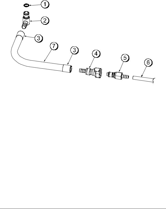
X59304 Syrup Line Assembly - Thin Viscosity Syrup
Figure 7
ITEM |
DESCRIPTION |
PART NO. |
|
|
|
1 |
FERRULE-.650 ID NP BRASS |
029834 |
|
|
|
2 |
INSERT-QD-CPC-3/8 BARB |
056675 |
|
|
|
3 |
O-RING-11MM ID X 2MM W |
053890 |
|
GREEN (25 TO BAG) |
|
4 |
TUBE-NYLOBRADE 3/8IDX5/8 |
500038-9 |
|
|
|
5 |
FITTING-SYRUP ELBOW |
056651 |
|
|
|
ITEM |
DESCRIPTION |
PART NO. |
|
|
|
6 |
VALVE-CHECK-DUCKBILL |
500598 |
|
|
|
7 |
FITTING-SYRUP NOSE .075 |
056649 |
|
SLOT |
|
8 |
O-RING-11MM ID X 2MM W |
053890 |
|
GREEN |
|
Operator Parts Identification |
16 |
Model C606 |
|
|
|

X56652 Syrup Line Assembly - Thick Viscosity Shake Syrup (Optional)
Figure 8
ITEM |
DESCRIPTION |
PART NO. |
|
|
|
1 |
FERRULE-.625 ID |
053036 |
|
|
|
2 |
FITTING BARB |
056675 |
|
|
|
3 |
O-RING |
500205 |
|
|
|
4 |
HOSE-BEVERAGE |
053052-9 |
|
|
|
5 |
FITTING-SYRUP ELBOW |
056651 |
|
|
|
ITEM |
DESCRIPTION |
PART NO. |
|
|
|
6 |
VALVE-CHECK DUCKBILL |
500598 |
|
|
|
7 |
FITTING-SYRUP NOSE |
056650 |
|
(LARGE SLOT) |
|
8 |
O-RING-11 MM GREEN |
053890 |
|
(SYRUP HOLE PLUG) |
|
Model C606 |
17 |
Operator Parts Identification |
|
|
|
X58450 Syrup Line Assembly - Syrup-In-Bag Option
Figure 9
ITEM |
DESCRIPTION |
PART NO. |
|
|
|
1 |
O-RING 1/2 OD X .070 |
024278 |
|
|
|
2 |
FITTING-MALE |
054526 |
|
|
|
3 |
FERRULE- .625 ID NP BRASS |
053036 |
|
|
|
4 |
COUPLING-QD FEMALE 3/8 |
058451 |
|
|
|
ITEM |
DESCRIPTION |
PART NO. |
|
|
|
5 |
COUPLING-QD MALE 1/4 BARB |
058452 |
|
|
|
6 |
TUBE-VINYL 3/16 ID X 1/16 W |
020940-8 |
|
(R30314) |
|
7 |
HOSE-BEVERAGE 3/8 ID |
053052-36 |
|
|
|
Operator Parts Identification |
18 |
Model C606 |
|
|
|
Mix Hopper - Top View
Figure 10
ITEM |
DESCRIPTION |
PART NO. |
|
|
|
1 |
SLEEVE A.-MIX PUMP |
X44761 |
|
|
|
2 |
PROBE A.MIX OUT |
X41348 |
|
|
|
3 |
HOUSING A.-AGITATOR |
X51664 |
|
(SHAKE) |
|
3a |
MAGNET A.-AGITATOR-INNER |
X41733 |
4a |
|
|
ITEM |
DESCRIPTION |
PART NO. |
|
|
|
4 |
HOUSING A.-AGITATOR |
X51661 |
|
(SOFT SERVE) |
|
5 |
PROBE A.-MIX LOW |
X42077 |
|
|
|
6 |
CAP-MAGNET |
080826 |
|
|
|
120522
Model C606 |
19 |
Operator Parts Identification |
|
|
|
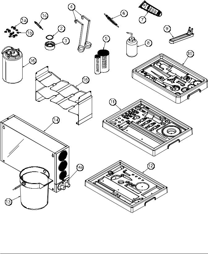
Accessories
Figure 11
140624
Operator Parts Identification |
20 |
Model C606 |
|
|
|

Accessories (See Figure 11)
ITEM |
DESCRIPTION |
PART NO. |
|
|
|
1 |
KIT A.-SYRUP PLUG KIT TTS |
X58474 |
|
|
|
1a |
PLUG-SYRUP PORT TTS |
053867 |
|
|
|
1b |
O-RING-11MM ID X 2MM W |
053890 |
|
GREEN (25 TO BAG) |
|
1c |
TOOL-SEAL INSTALL-REMOVE |
035460 |
|
|
|
2 |
O-RING-1-11/16 OD X.139W |
041923 |
|
(25 TO BAG) |
|
|
(DRAW VALVE CAP) |
|
3 |
CAP A.-VALVE-DRAW |
X54704 |
|
|
|
4 |
LADLE-1 OZ-120D BEND |
033637-1 |
|
|
|
5 |
CUP-DIVIDED SYRUP |
017203 |
|
|
|
6 |
TOOL-O-RING REMOVAL |
048260-WHT |
|
|
|
7 |
LUBRICANT-TAYLOR HI PERF |
048232 |
|
|
|
8 |
BOTTLE-WASH-PLASTIC |
044818 |
|
|
|
9 |
TOOL-MIX PUMP SHAFT |
057167 |
|
REMOVAL |
|
10 |
TRAY-PARTS-PUMP-SIMPL |
056525 |
|
|
|
11 |
TRAY-PARTS-SHAKE SIDE |
059088 |
|
|
|
ITEM |
DESCRIPTION |
PART NO. |
|
|
|
12 |
TRAY-PARTS-SS SIDE |
059087 |
|
|
|
13 |
PAIL-10 QT. |
013163 |
|
|
|
14 |
DISPENSER A.-CUP-2 CONE |
X56121 |
|
|
|
14a |
BAFFLE-RUBBER CONE |
052193 |
|
|
|
15 |
TRAY A.-SYRUP (OPTIONAL |
X59143 |
|
SYRUP IN BAG SYSTEM) |
|
16 |
TANK-SYRUP 4QT. PSD |
056673 |
|
(OPTIONAL 4 TANK SYRUP |
|
|
SYSTEM) |
|
* |
KIT A.-PERISTALTIC PUMP |
X54978 |
|
TUBE |
|
* |
KIT A.-TOPPING PUMP |
X53795 |
|
SPARES |
|
* |
KIT A.-TUNE UP |
X49463-59 |
|
|
|
* |
DEFLECTOR-BLOWER |
047912 |
|
EXHAUST |
|
* |
BOX-TOOL 15 INCH PLASTIC |
058669 |
|
|
|
*NOT SHOWN
140718
Model C606 |
21 |
Operator Parts Identification |
|
|
|
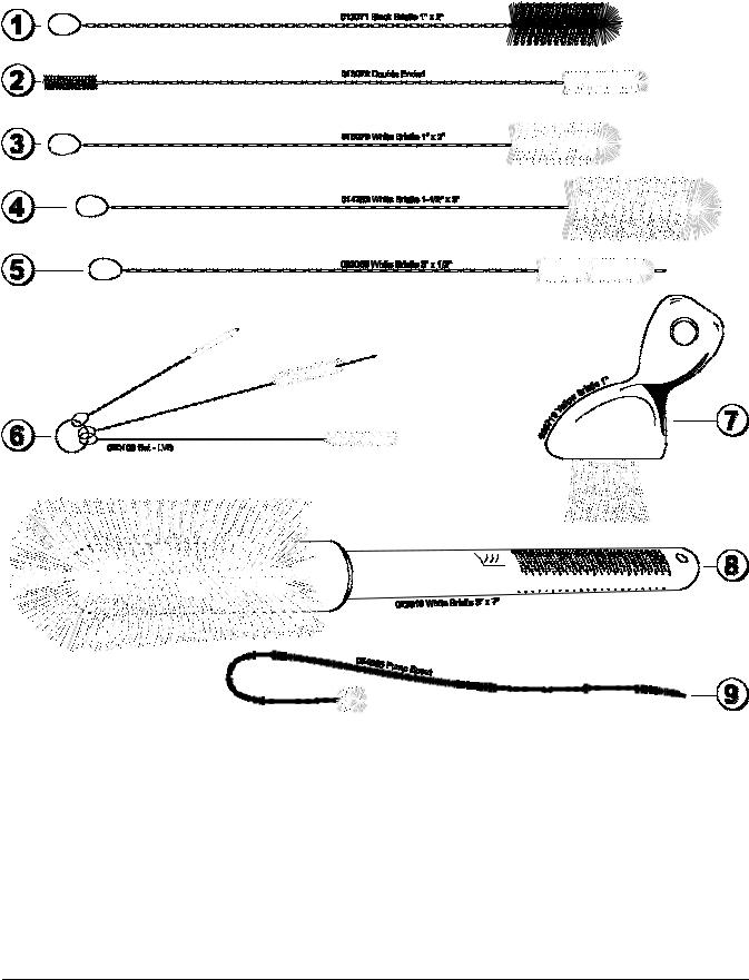
X44127 Brush Kit Assembly
Figure 12
ITEM |
DESCRIPTION |
PART NO. |
|
|
|
1 |
BLACK BRISTLE BRUSH |
013071 |
|
|
|
2 |
DOUBLE END BRUSH |
013072 |
|
|
|
3 |
WHITE BRISTLE BRUSH |
013073 |
|
(1” x 2”) |
|
4 |
WHITE BRISTLE BRUSH |
014753 |
|
(1-1/2” x 3”) |
|
5 |
WHITE BRISTLE BRUSH |
033059 |
|
(1/2” x 3”) |
|
ITEM |
DESCRIPTION |
PART NO. |
|
|
|
6 |
BRUSH Set (3) |
050103 |
|
|
|
7 |
YELLOW BRISTLE BRUSH |
039719 |
|
|
|
8 |
WHITE BRISTLE BRUSH |
023316 |
|
(3” x 7”) |
|
9 |
BRUSH-PUMP SPOUT |
054068 |
|
|
|
Operator Parts Identification |
22 |
Model C606 |
|
|
|
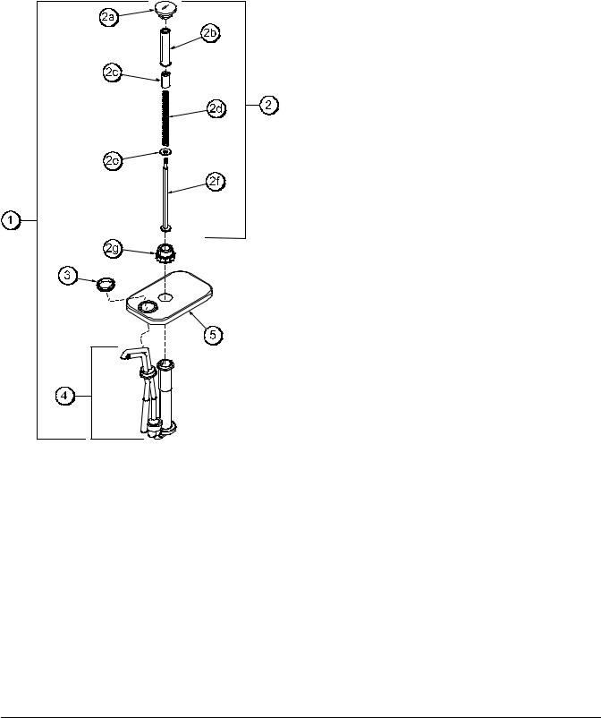
X53800-BRN/TAN Syrup Pump
ITEM |
DESCRIPTION |
PART NO. |
|
|
|
|
|
1 |
PUMP A.-SYRUP-HEATED |
X53800-BRN |
|
PUMP A.-SYRUP-HEATED |
X53800-TAN |
||
|
|||
|
|
|
|
2 |
PLUNGER A.-BROWN |
X36576-BRN |
|
|
|
||
PLUNGER A.-TAN |
X36576-TAN |
||
|
|||
|
|
|
|
|
KNOB-PLUNGER BROWN- |
032762-BRN |
|
2a |
SYRUP PUMP |
|
|
KNOB-PLUNGER TAN-SYRUP |
032762-TAN |
||
|
|||
|
PUMP |
|
|
|
|
|
|
2b |
TUBE-PLUNGER |
032757 |
|
|
|
|
|
2c |
INSERT-PLUNGER |
032758 |
|
|
|
|
|
2d |
SPRING-PLUNGER-SYRUP |
032761 |
|
|
PUMP |
|
|
2e |
WASHER-NYLON |
032760 |
|
|
|
|
|
2f |
PLUNGER |
036578 |
|
|
|
|
|
2g |
SEAL A. |
X33057 |
|
|
|
|
|
2h |
NUT-PLUNGER |
036577 |
|
|
|
|
|
3 |
NUT-LOCK-SYRUP PUMP |
039680 |
|
|
|
|
|
4 |
PUMP A.-SYRUP HEATED |
X53798-SER |
|
|
SHALLOW |
|
|
5 |
LID |
036579 |
|
|
|
|
NOTE: SHOWN FOR REFERENCE ONLY. NOT
SUPPLIED WITH NEW UNITS.
Figure 13
140624
Model C606 |
23 |
Operator Parts Identification |
|
|
|
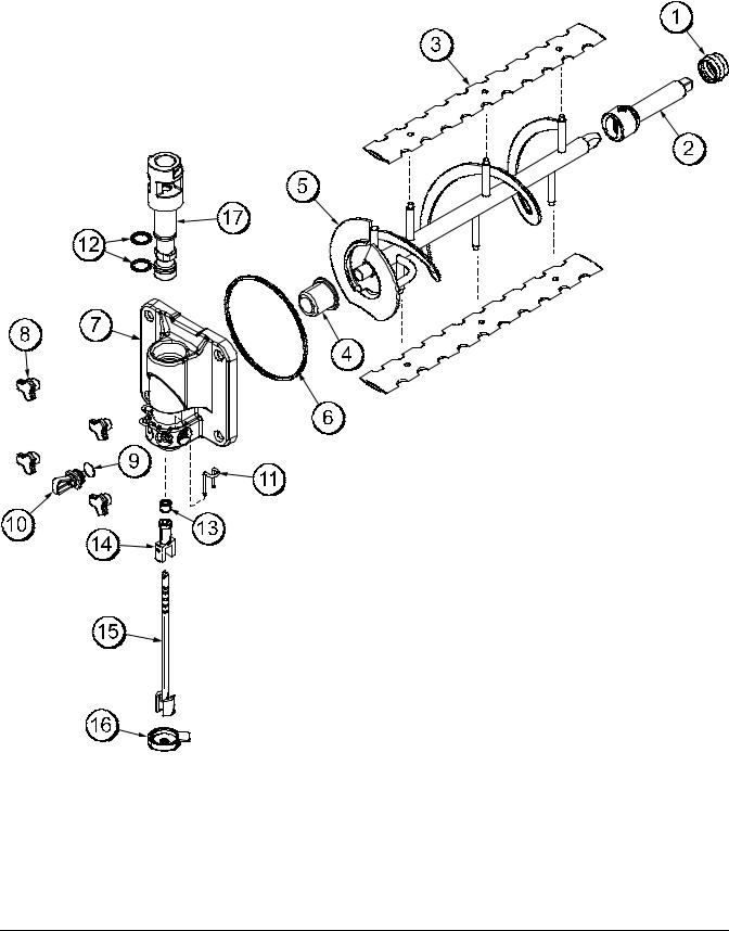
Beater Door Assembly - Shake Side
Figure 14
Operator Parts Identification |
24 |
Model C606 |
|
|
|
 Loading...