


3-859-268-11(1)
XES-M50
Operating Instructions
ã 1997 by Sony Corporation


Stereo Power
Amplifier
Operating Instructions
Before operating the unit, please read this manual thoroughly and retain it for future reference.
Owner’s Record
The model and serial numbers are located on the bottom of the unit.
Record the serial number in the space provided below.
Refer to these numbers whenever you call upon your Sony dealer regarding this product.
Model No. XES-M50 Serial No.

Introduction |
|
Contents |
|
Introduction |
|
Contents .............................................. |
2 |
Features ............................................... |
3 |
Installation |
|
Installation .......................................... |
4 |
Before Installation ....................... |
4 |
Parts List ....................................... |
4 |
Installation Instructions ............. |
5 |
Connections |
|
Before Connecting ............................. |
6 |
System Connections (XES Series) .... |
7 |
Power Supply Lead Connections .... |
8 |
XES Series Speaker Connections ..... |
9 |
Speaker Connections |
|
When Used as a Monophonic |
|
Amplifier (Bridging |
|
Connections) .............................. |
10 |
Dual Mode Connections .......... |
11 |
Using a Monophonic Amplifier |
|
for Subwoofer Use (Bridging |
|
Connection) ................................ |
13 |
Adjustment |
|
NFB Switch ....................................... |
14 |
Phase Switch .................................... |
14 |
Input Level Adjustments ................ |
15 |
Other |
|
Precautions ....................................... |
16 |
Precautions on Use ................... |
16 |
Fuse Replacement ..................... |
16 |
Troubleshooting Guide .................. |
17 |
Specifications ................................... |
18 |
Power Supply Wire ......................... |
19 |
2 Introduction

Features
Left and right channel independent monophonic configuration
Two amplifiers are laid out in a single unit and everything is kept separate, even the power supply terminals, so a clear sound quality is realized with almost no interference between signals of the left and right channels.
Equipped with a Non-NFB circuit for clear sound reproduction
Conventional NFB (Negative Feed Back) circuits are effective at reducing the distortion produced by the amplifier but are susceptible to the affects of sound muddiness from the reverse electromotive force produced by the speakers. This system is equipped with a Non-NFB circuit for handling this problem so a clear, unmuddied sound is reproduced.
In addition, output transistor source resistance is removed and the speakers are driven directly. Because there is no source resistance, switching distortion is suppressed and pure transmission is possible.
Pre-Regulated Power Supply with no fluctuations in constant voltage even during large outputs of power and when the engine is running
Once constant voltage has been attained, a Pre-Regulated Power Supply that steps up with a DC/DC converter is employed for the power source of the voltage amplification stage. A choke coil-less method is employed in the
power input of the current amplification stage and the current drive capacity is ensured. As a result of these, a powerful power source is realized that is capable of driving both channels at 200 W each at 1 ohm.
FET Input Circuit
Differential amplifier circuit with positive/negative symmetry due to the use of dual FET. Dual FET with tips of all characteristics contained in one package are used, and allowances have been made for thermal coupling. In addition, using the high input impedance of the FET gates, a DC input circuit is attained that does not use DC coupling capacitors.
High Quality Parts Used
Parts that combine reliability with high sound quality are used in the system including newly developed aluminum power capacitors, power transformers in which allowances have been made for vibration, a planed terminal board, RCA pin jacks, a gold-plated oxygen free copper substrate, and carbon resistant materials, etc.
Introduction 3
Installation
Installation
Before Installation
•Mount the unit either inside the trunk or under a seat.
•To mount the unit you will need a mounting board that is sufficiently thick (at least 15 mm (19/32 in.)) and strong.
•When mounting the unit horizontally, mount it on the heat sink surface. Also, avoid installing the unit under the carpet as the heat dissipation will be considerably impaired.
•Because a DC-DC converter is used in this unit, if it is mounted near the radio or antenna, reception of radio and television broadcasts will be hindered. Set the unit up in a place as far away as possible from the radio and antenna.
•Do not install it in a place where it is exposed to high temperatures, such as in direct sunlight, or where it is directly exposed to hot air from the heater.
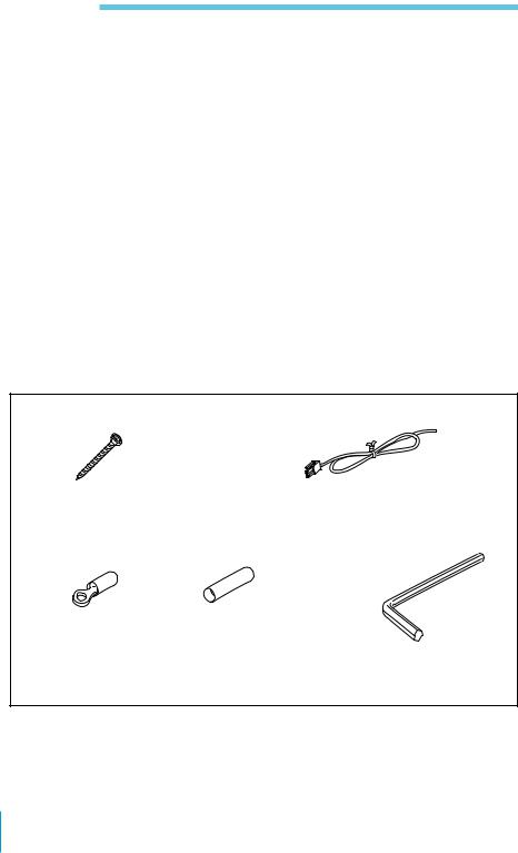
Parts List
The circled numbers indicate the number of the part to use that is referred to in the explanation of how to install the unit.
1 |
2 |
|
× 4 |
|
× 2 |
|
|
|
Screws (φ5 × 40 mm) |
Remote cords (blue/white) |
|
(φ 7/32 × 1 5/8 in.) |
|
|
3 |
4 |
5 |
red × 4, |
× 2 |
|
black × 4 |
|
× 1 |
|
|
|
Crimp type terminals |
Blue junction crimp type |
Hexagonal wrench |
|
terminals (for junctions in |
|
|
the wiring) |
|
4 Installation

Installation Instructions
Prepare a mounting board that is sufficiently thick (at least 15 mm (19/32 in.)) and strong.
1 Remove the cover.
Loosen and remove the 8 screws using the hexagonal wrench 5.
Screw positions
Hexagonal wrench 5
2 Mount the unit on the mounting board.
Place the template (printed on the carton box) on the mounting board, determine where the unit will be mounted and mark the hole positions. Drill holes of at least 3 mm (1/8 in.) in diameter at the places you have marked, and using the screws 1, secure the unit on the mounting board.
 Screws 1
Mounting board
3 Attach the cover.
Reattach the cover with the hexagonal wrench 5 using the screws removed in Step 1.
Installation 5
Connections
Before Connecting
•Before making any connections, disconnect from the negative terminal of the car battery to avoid short circuits.
•Always connect the power supply lead last.
•Install the input and output cords away from the power supply lead as running them close together can generate some interference noise.
•This unit is a high powered amplifier. Therefore, it may not perform to its full potential if used with the speaker cords already established in the car.
•Connecting the }terminal of the speaker system to the car chassis or connecting the }terminal of the right speaker with that of the left speaker may result in damage.
•Be sure to use speakers with an adequate power rating. Because this amplifier puts out high power, if you use small capacity speakers, not only will the amplifier not perform at its
full potential, but the speakers may become damaged as well.
•Use speakers with an impedance of 1- 8 ohms. (2-8 ohms with a bridging connection)
•Do not connect the active speaker (speaker built into the amplifier) to a speaker terminal on the amplifier as this may damage the speaker.
Caution
If your car is equipped with a computer for navigation or some other purpose, do not remove the ground wire from the negative terminal of the car battery. If you disconnect the wire, the computer memory will be completely erased. With these types of vehicles, without disconnecting the power supply lead from the negative terminal of the battery, make all the other connections first leaving the connection to the power supply for last.
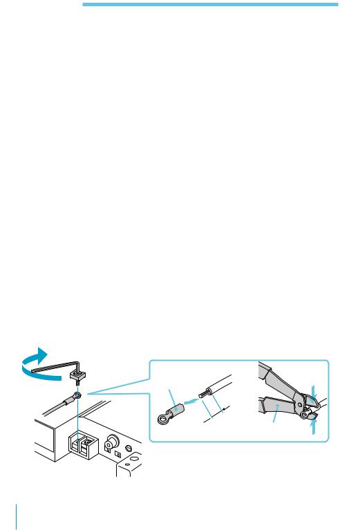
Make the power supply lead and speaker connection as illustrated below.
Crimp type |
b |
terminal 3 |
 5mm .) in 7/32 (
Crimping wrench
In order not to damage the screws, the tightening torque should be no more than 1 Nm.
6 Connections
 Loading...