


3-859-466-11 (1)
Integrated
Amplifier/Video
Cassette Recorder
Operating Instructions
j
G
SLV-AV100U/C
©1997 by Sony Corporation

WARNING
To prevent fire or shock hazard, do not expose the unit to rain or moisture.
CAUTION
RISK OF ELECTRIC SHOCK
DO NOT OPEN
CAUTION : TO REDUCE THE RISK OF ELECTRIC SHOCK,
DO NOT REMOVE COVER (OR BACK).
NO USER-SERVICEABLE PARTS INSIDE.
REFER SERVICING TO QUALIFIED SERVICE PERSONNEL.
This symbol is intended to alert the user to the presence of uninsulated “dangerous voltage” within the product’s enclosure that may be of sufficient magnitude to constitute a risk of electric shock to persons.
This symbol is intended to alert the user to the presence of important operating and maintenance (servicing) instructions in the literature accompanying the appliance.
CAUTION
To prevent electric shock, do not use this polarized AC plug with an extension cord, receptacle or other outlet unless the blades can be fully inserted to prevent blade exposure.
Precautions
Safety
•Operate the unit only on 120 V AC, 60 Hz.
•If anything falls into the cabinet, unplug the unit and have it checked by qualified personnel before operating it any further.
•One blade of the plug is wider than the other for the purpose of safety and will fit into the power outlet only one way. If you are unable to insert the plug fully into the outlet, contact your Sony dealer.
•Unplug the unit from the wall outlet if you do not intend to use it for an extended period of time. To disconnect the cord, pull it out by the plug, never by the cord.
Installing
•Allow adequate air circulation to prevent internal heat buildup.
•Do not place the unit on surfaces (rugs, blankets, etc.) or near materials (curtains, draperies) that may block the ventilation slots.
•Do not install the appliance in a confined space, such as a bookcase or built-in cabinet.
•Do not install the unit near heat sources such as radiators or air ducts, or in a place subject to direct sunlight, excessive dust, mechanical vibration or shock.
•Do not install the unit in an inclined position. It is designed to be operated in a horizontal position only.
•Keep the unit and cassettes away from equipment with strong magnets, such as microwave ovens or large loudspeakers.
•Do not place heavy objects on the unit.
•If the unit is brought directly from a cold to a warm location, moisture may condense inside the VCR and cause damage to the video head and tape. When you first install the unit, or when you move it from a cold to a warm location, wait for about one hour before operating the unit.
Information
For customers in the USA
This equipment has been tested and found to comply with the limits for a Class B digital device, pursuant to Part 15 of the FCC Rules. These limits are designed to provide reasonable protection against harmful interference in a residential installation. This equipment generates, uses, and can radiate radio frequency energy and, if not installed and used in accordance with the instructions, may cause harmful interference to radio communications. However, there is no guarantee that interference will not occur in a particular installation. If this equipment does cause harmful interference to radio or television reception, which can be determined by turning the equipment off and on, the user is encouraged to try to correct the interference by one or more of the following measures:
•Reorient or relocate the receiving antenna.
•Increase the separation between the equipment and receiver.
•Connect the equipment into an outlet on a circuit different from that to which the receiver is connected.
•Consult the dealer or an experienced radio/TV technician
for help.
You are cautioned that any changes or modifications not expressly approved in this manual could void your authority to operate this equipment.
Caution
Television programs, films, video tapes and other materials may be copyrighted. Unauthorized recording of such material may be contrary to the provisions of the copyright laws. Also, use of this recorder with cable television transmission may require authorization from the cable television transmission and/or program owner.
Owner’s record
The model number is located at the rear and front of the unit and the serial number on the top. Record these numbers in the spaces provided below. Refer to them whenever you call upon your Sony dealer regarding this product.
Model No. _____________________
Serial No. ______________________
2 Introduction

Table of contents
*1 VCR Plus+ and PlusCode are trademarks of Gemstar Development Corporation. VCR Plus+ system is manufactured under license from Gemstar Development Corporation.
*2 This unit uses the Dolby Surround system, manufactured under license from Dolby Laboratories Licensing Corporation.
DOLBY, the double-D symbol a, and PRO LOGIC are trademarks of Dolby Laboratories Licensing Corporation.
Getting Started
4Step 1: Unpacking
5Step 2: Setting up the remote commander
6Step 3: Speaker systems hookup
8 Step 4: Various audio/video hookups
11 Step 5: TV antenna or cable hookups
30 Adjusting the SOUND SET with EASY SET UP
33 Setting the clock
35 Setting up cable box control
39 Presetting channels
43 Setting up VCR Plus+ *1
45 Presetting radio stations
Basic VCR / Radio Operations
47 Playing a video tape
49Using the pre-programed sound fields
50Recording TV programs
51Recording TV programs using VCR Plus+
54Setting the timer manually
56Checking/changing/cancelling timer settings
58Listening to the radio
Audio/Video Equipment Operations
59 Selecting the equipment
62 Controlling VCRs
64 Controlling the TV
66Playing back a CD
67Controlling a cassette deck
69Controlling a DAT deck
71Controlling an MD deck
73Controlling an LD player
Sound Field Operations
75 Taking advantage of the sound fields
77Getting the most out of Dolby Pro Logic Surround*2 sound
78Customizing the sound fields
82 Reconfiguring the PROLOGIC and THEATER sound fields
Advanced VCR Operations
84Playing/searching at various speeds
85Recording TV programs using the quick timer
86Recording stereo and bilingual programs
87Searching using the index function
88Adjusting the picture
89Changing menu options
Editing
90 Recording from another VCR or LD player
Additional Information
91Customizing the remote commander function buttons
92General setup information
94 Troubleshooting
97Specifications
98Index to parts and controls
103Index
Back Quick reference to using the VCR
Cover
Introduction 3
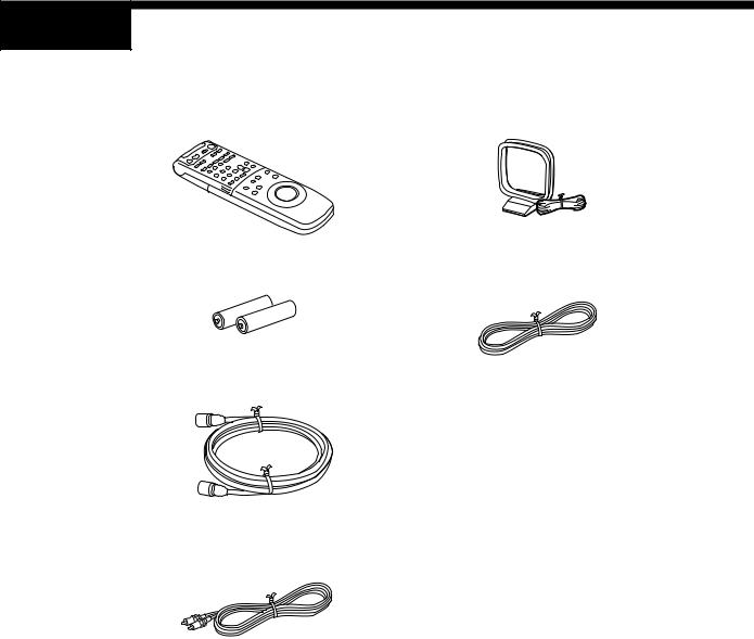
Step 1 Unpacking
Check that you have received the following items with the unit:
• Remote commander |
• AM loop antenna |
• Size AA (R6) batteries |
• FM wire antenna |
•75-ohm coaxial cable with F-type connectors
•Video cable
(1 phono to 1 phono)
4 |
Getting Started |
|
|
Step 2 Setting up the remote commander
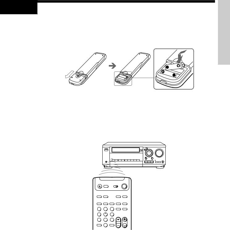
Inserting the batteries
Insert two size AA (R6) batteries matching the + and – on the batteries to the diagram inside the battery compartment.
Using the remote commander
You can use this remote commander to operate this unit, a TV, other VCRs, an LD deck, CD player, cassette deck, DAT deck, and MD deck (all equipment must be made by Sony).
For details on how to operate other equipment with this remote commander, see “Audio/ Video Equipment Operations” from page 59.
Started Getting
Remote sensor 
1 2 3
4 5 6
7 8 9
>10 0
Notes
•The remote commander is initially set to control this unit. However, if it doesn’t control the unit, press VHS TUNER first. If the remote commander still doesn’t operate, read “Controlling VCRs” on page 62 first.
•With normal use, the batteries should last about three to six months.
•If you do not use the remote commander for an extended period of time, remove the batteries to avoid possible damage from battery leakage.
•Do not use a new battery with an old one.
•Do not use different types of batteries.
Getting Started |
5 |
|
|
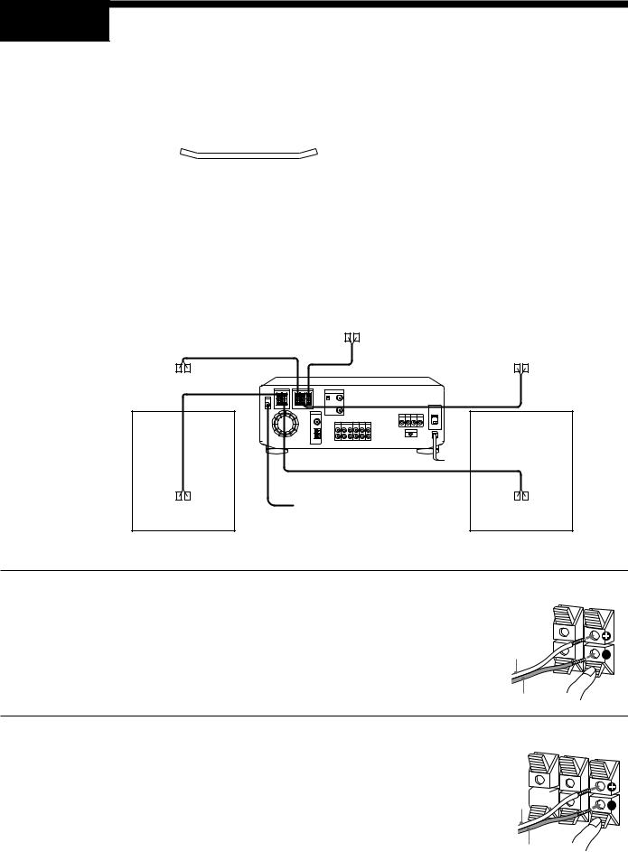
Step 3 Speaker systems hookup
To get the best possible sound from the unit, connect front (left and right), center, and rear (left and right) speakers. You need to connect either the center or rear speakers as well as the front speakers to enjoy Dolby Pro Logic Surround sound.
Before you connect...
•Prepare speaker cords (one for each speaker) (not supplied).
(+)
 (+)
(+)
(–)
 (–)
(–)
•Be sure to match the speaker cords to the appropriate terminals on the components: + to +, and – to –. (If the cords are reversed, the sound will be distorted and the bass sound will not be reproduced well.)
•Do not connect the AC power cord until you finish all the connections through “Step 5 : TV antenna or cable hookups” on page 11.
•Be sure to make connections firmly to avoid hum and noise.
Rear right speaker |
|
|
|
Center speaker |
|
|
|
Rear left speaker |
|
|
|
|
|
|
|
|
|
|
|
|
|
|
|
|
|
|
|
|
|
|
|
|
|
|
|
|
|
|
|
|
|
|
|
|
|
|
|
|
|
|
|
|
|
|
|
|
|
|
|
|
|
|
|
Active woofer |
|
Front right speaker |
|
Front left speaker |
|
|
|
1
2
Connect the front speakers to the FRONT SPEAKERS L/R connectors.
Twist about 15 mm of the stripped ends of the cord. Then insert the stripped ends into the connectors as shown on the right.
Connect the center speaker to the SURROUND SPEAKERS CENTER connectors.
Repeat step 1 above for the center speaker.
If you don’t have a center speaker, skip this step.
FRONT |
||
R |
SPEAKERS |
|
L |
||
|
||
(+)
(–)
SURROUND R-REAR-L
(+)
(–)
SPEAKERS CENTER
6 |
Getting Started |
|
|

3 |
Connect the rear speakers to the SURROUND |
SPEAKERS REAR L/R connectors. |
Repeat step 1 above for the surround speakers.
If you don’t have rear speakers, skip this step.
Note
•Be sure to connect both left and right speakers. If you connect only one speaker, the rear speaker won’t reproduce the sound.
(+)
(–)
SURROUND R-REAR-L
SPEAKERS CENTER
Placing the speakers
For optimum surround sound effect, place your speakers as shown below.
Rear speaker
60-90 cm
Front speaker
45º
Tips
•Position the center speaker so the face of the speaker is aligned evenly with, or slightly behind the faces of the front left and right speakers.
•Mount the surround (rear) left and right speakers on the walls so they face each other.
•Position the front left and right speakers and center speaker as close to the same height as possible.
Started Getting
Connecting an active woofer
For further sound improvement, connect an active woofer to MIX OUT with an audio cable (not supplied). The active woofer will increase bass response. The position of the active woofer does not affect the sound quality very much.
This unit |
Active woofer |
MIX |
INPUT |
OUT |
|
Audio cable (not supplied)
Listening through the headphones
Connect the headphones to PHONES. No sound will be reproduced from the speakers.
PHONES |
Getting Started |
7 |
|
|

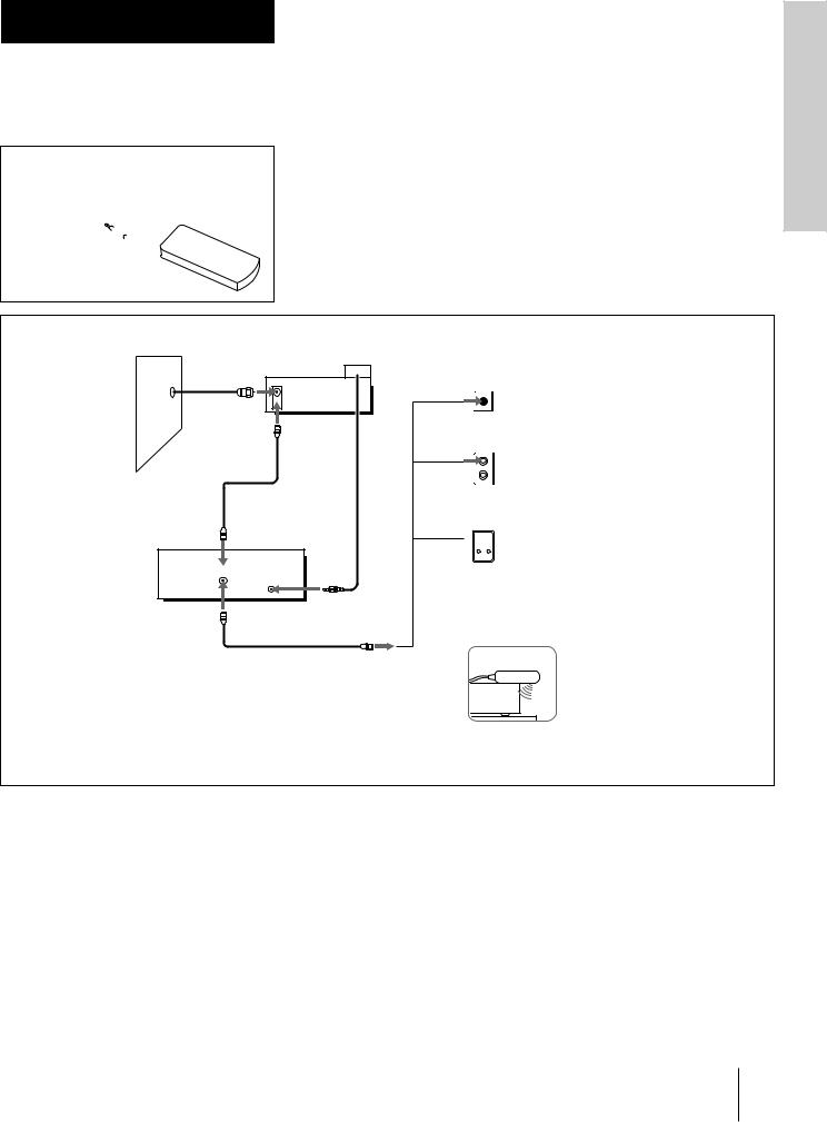
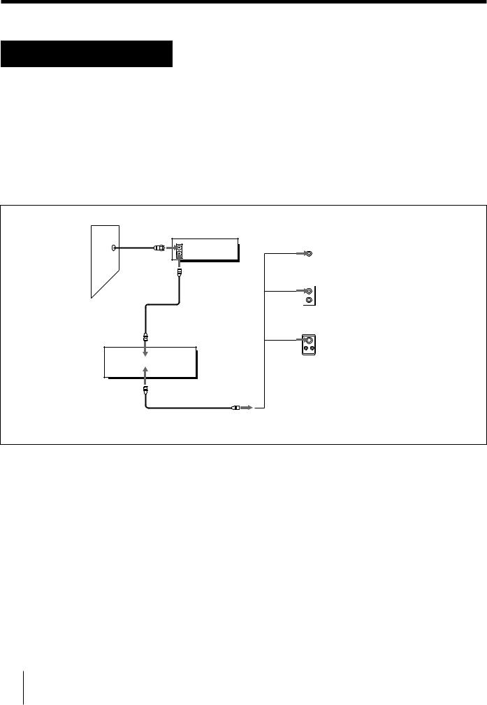
Step 4 Various audio/video hookups
The following connections with various audio/video equipment are recommended examples. The actual connections may vary depending on the equipment you have.
Before you connect....
• Prepare audio (not supplied) and video cables referring to the following table.
Audio cable |
|
Video cable |
|
|
White (L) |
White (L) |
Yellow |
Yellow |
|
Red (R) |
Red (R) |
|||
|
|
|||
Equipment |
|
Necessary cable for each piece of equipment |
||
Tuner/CD player |
|
One audio cable |
|
|
MD deck/DAT deck/cassette deck |
|
Two audio cables |
|
|
Satellite tuner/LD player/other VCR |
|
One video cable and one audio cable |
|
|
TV |
|
One video cable and one audio cable |
|
|
Monitor |
|
One video cable |
|
|
•Turn off the power to all equipment before making any connections.
•Do not connect the AC power cord until all of the connections are complete.
•Be sure to make connections firmly to avoid hum and noise.
FM wire antenna |
|
MD deck |
|
|
|
or |
|
|
|
|
|
|
DSS receiver |
|
|
|
DAT deck |
|
|
|
|
|
|
|
|
|
or |
AUDIO |
VIDEO |
AM loop |
Cassette deck |
OUT |
OUT |
|
REC IN |
REC OUT |
|
|
|
antena |
|
|
||
ANTENNA |
VIDEO |
|
|
|
|
|
|
MONITOR |
TV |
VIDEO 1 |
LINE |
VIDEO OUT |
IN |
IN |
IN |
AUDIO |
|
|
|
FM |
CD |
TAPE / MD |
TV |
VIDEO 1 |
LINE |
|
IN |
REC OUT IN |
IN |
IN |
IN |
AM |
L |
|
|
|
|
|
|
|
|
|
|
|
R |
|
|
|
|
VIDEO TV IN
(Monitor) 


: Signal flow
|
VIDEO |
AUDIO |
VIDEO |
|
|
OUT |
OUT |
||
|
OUT |
|
||
|
|
|
|
|
OUT |
|
|
|
LD player |
|
TV |
|
or |
|
|
AUDIO |
|
||
CD player |
|
|
Other VCR |
|
OUT |
|
|
||
|
|
|
|
|
to wall outlet |
|
|
|
|
8 |
Getting Started |
|
|

1
2
Connect your audio/video equipment using audio |
|
|
and video cables (not supplied) referring to the |
|
|
illustration on page 8. |
Getting |
|
Make sure you connect the audio and video cable plugs to |
||
|
||
jacks of the same color. |
Started |
|
Connect the AC power cord to the wall outlet. |
||
|
||
|
|
Connecting to the front VIDEO 2 INPUT jacks
Video game |
|
|
|
AUDIO OUT |
|
|
VIDEO |
Audio/video |
Camcorder |
cable (not |
|
OUT |
supplied) |
|
|
|
|
Other VCR |
|
|
|
|
VIDEO L AUDIO R |
|
|
VIDEO 2 INPUT |
: Signal flow
Notes
•Make sure you connect the audio/video plugs to jacks of the same color.
•If the other VCR is a monaural type, connect only the VIDEO and AUDIO L jacks.
Connecting to the AC OUTLET
You can connect an audio component (or components through an optional multi-outlet extension cord) to AC OUTLET on the rear of the unit. The power is supplied to AC OUTLET while the unit is turned on. The power supply stops when you turn off the unit. Using this function, you can turn on and turn off all the audio components connected to AC OUTLET at the same time if you leave those components’ power switches on.
Cautions
•Make sure you comply with the laws and regulations in your country for this connection.
•Make sure that the power consumption of the components connected to AC OUTLET doesn’t exceed 120 watts. Do not connect high-wattage electrical home appliances such as electric irons, fans, or TVs to this outlet.
Notes
•The power will not be supplied to the components as long as the unit is turned off. Any electronic memory of the components may be cleared if you make this connection.
•Some audio components may not turn on with this connection.
Getting Started |
9 |
|
|
Step 4 Various audio/video hookups (continued)
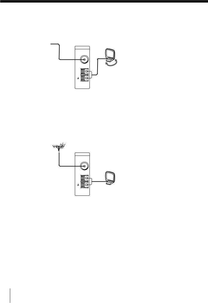
Connecting FM/AM antennas
To receive radio broadcasts with this unit, connect the FM/AM antennas (supplied).
FM wire antenna
After connecting the wire antenna, keep it as horizontal as possible.
ANTENNA
FM
AM
AM loop antenna
Adjust the direction.
If AM reception is poor
We recommend that you purchase and connect the optional Sony antenna to the unit if reception is weakened by ferroconcrete used in the construction of your apartment or building.
If you have poor FM reception
Connect a 75-ohm coaxial cable (not supplied) to an FM outdoor antenna.
FM outdoor antenna
Receiver
ANTENNA
FM
AM
Note
•To prevent noise pick-up, keep the AM loop antenna away from the unit and TV. When the noise is not cleared yet, turn off the TV.
10 Getting Started
Step 5
*DSS is a registered trademark of DIRECTV, Inc., a unit of Hughes Electronics Corporation.
TV antenna or cable hookups
Selecting the best hookup option
There are many ways in which your VCR can be hooked up. To hook up your VCR so that it works best for you, first scan through the table below. Then use the accompanying diagrams and procedures on the following pages to set up your VCR.
If you have |
Use |
Refer to |
|
|
|
TV that has video input |
Video (V) hookup, then follow one |
Page 12 |
|
of the hookups below. |
|
|
|
|
Cable box that is compatible with the |
Hookup 1 |
Pages 13 to 15 |
VCR’s cable box control feature |
|
|
|
|
|
No cable box or incompatible cable box |
Hookup 2 |
Pages 16 to18 |
with only a few scrambled channels |
|
|
|
|
|
Antenna only, no cable TV |
Hookup 3 |
Pages 19 to 21 |
|
|
|
Incompatible cable box with many |
Hookup 4 |
Pages 22 to 24 |
scrambled channels |
|
|
|
|
|
DSS * receiver |
Hookup 5 |
Pages 25 to 26 |
Incompatible cable box with only a few |
Hookup 6 |
Pages 27 to 29 |
scrambled channels, using an A/B switch |
|
|
|
|
|
After you’ve completed the connections, follow the instructions for setup. During setup, if you need more details on the procedure described, page numbers are provided where you can find complete, step-by-step instructions.
After you’ve completed the setup, you’re ready to use your unit’s VCR. Procedures differ depending on the hookup you used. For an overview, refer to “Quick reference to using the VCR” on the back cover.
Before you get started
•Turn off the power to all equipment.
•Do not connect the AC power cords until all of the connections are completed.
•Be sure you make connections firmly. Loose connections may cause picture distortion.
•If your TV doesn’t match any of the examples provided, see your nearest Sony dealer or qualified technician.
Started Getting
Getting Started 11

Step 5 TV antenna or cable hookups (continued)
Video (V) hookup
You will get a better picture by connecting your TV (monitor) to MONITOR VIDEO OUT jack as the illustration shown on page 8.
If you’re no planning to use your unit’s VCR to record programs
You’re finished setting up the unit’s VCR after you’ve made the connections shown on page 8.
If you want to record off-air or off your cable TV system
Complete these connections first, and then go to the following pages for antenna or cable hookups.
Caution
Connections between the VCR’s VHF/UHF connector and the antenna terminals of the TV receiver should be made only as shown in the following instructions. Failure to do so may result in operation that violates the regulations of the Federal Communications Commission regarding the use and operation of RF devices. Never connect the output of the VCR to an antenna or make simultaneous (parallel) antenna and VCR connections at the antenna terminals or your receiver.
Notes to CATV system installer
This reminder is provided to call the CATV system installer’s attention to Article 820-40 of the NEC that provides guidelines for proper grounding and, in particular, specifies that the cable ground shall be connected to the grounding system of the building, as close to the point of cable entry as practical.
12 Getting Started
Hookup 1
Using cable box control
A Cable Mouse is available as an optional accessory for this model. You can order directly from Sony by calling 1-800-488-7669 and asking for Cable Mouse
RM-CM101.
$14.95 + $3.00  (shipping, handling
and aplicable sales tax)
Recommended use
You should use this hookup if you have a cable box, especially if your cable system scrambles all or most channels. This hookup allows the VCR’s cable box control feature to control the channel on the cable box, simplifying the recording process. A list of compatible cable boxes is on page 36.
What you can do with this hookup
•Record any channel using the VCR’s cable box control feature to select channels on the cable box
What you can’t do
•Record with the cable box turned off
•Record one channel while watching another channel
Cable Mouse (not supplied)
Wall |
Cable box |
IN
 OUT
OUT
or
or
VCR
VHF/UHF
IN
OUT |
CONTROL S OUT |
Rear of TV
VHF/UHF
 A Match the type of connector on your TV: A, B, or C.
VHF |
|
|
|
B For connector types |
|
|
B and C, no UHF |
|
UHF |
connection is |
|
required. |
||
|
VHF
 C
C
UHF
Positioning the Cable Mouse
Place the Cable Mouse so that it hangs out over the cable box front.
Side view
Started Getting
Getting Started 13

Step 5 TV antenna or cable hookups (continued)
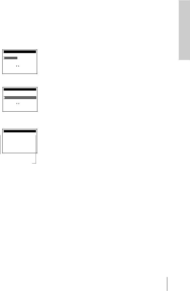
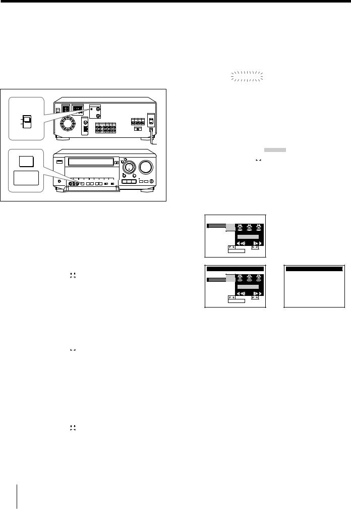
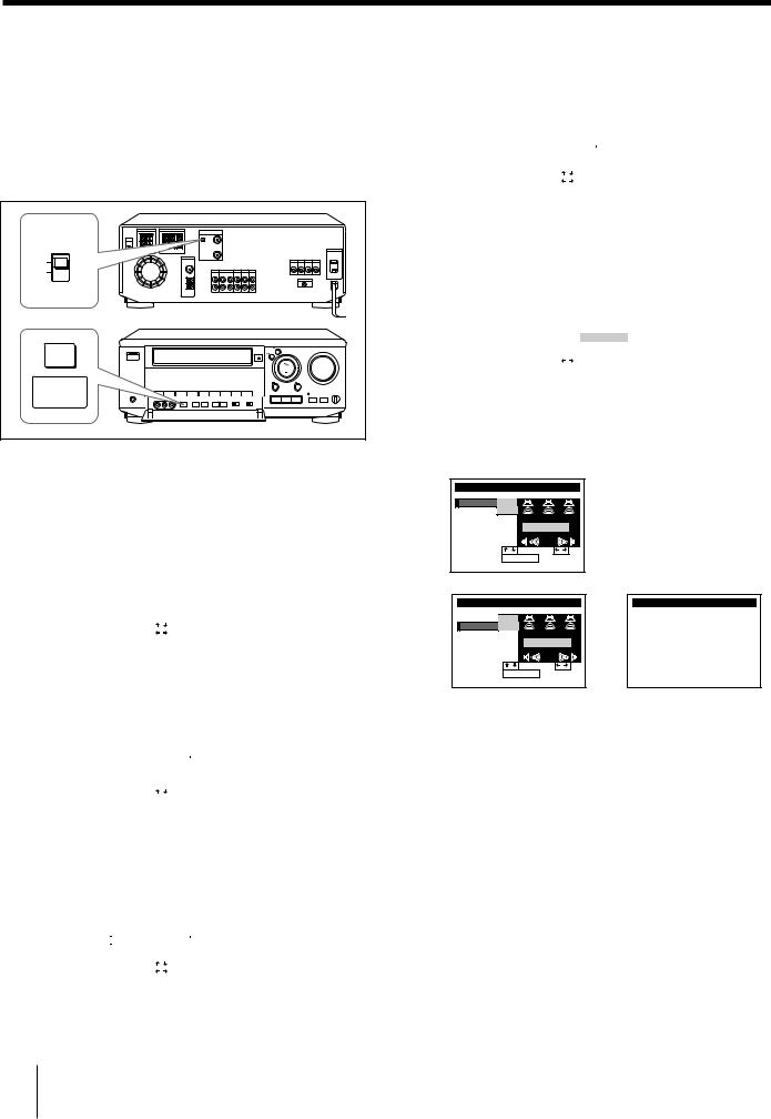
Hookup 1: VCR setup
1 Set the RF UNIT switch to CH 3 or CH 4, whichever channel is not used in your area. If both are used, set the switch to either channel.
For details, see page 92.
If you made V connections (from page 12), you can skip this step.
RF UNIT |
CH3 |
CH4 |
EASY |
SET UP |
2 Turn on your cable box.
3 Press EASY SET UP on the VCR.
1The CLOCK SET menu appears. Set the date and time and press EXECUTE. For details, see page 33.
|
|
|
|
|
|
|
|
|
|
SET UP |
|
|
CLOCK SET |
|
|||
|
|
|
|
|
||||
|
|
1 |
/ 1 / 1 9 9 7 WED 1 2 : 0 0 AM |
|
||||
|
SELECT |
: |
|
|
|
|
||
|
|
|
|
|||||
|
SET |
: |
|
|
|
|
||
|
NEXT |
: |
EXECUTE |
|
|
|||
|
|
|
|
|
|
|
|
|
2The CABLE BOX CONTROL menu appears. Select ON. For details, see page 35.
|
|
|
|
|
|
|
|
|
|
SET UP |
|
|
|
CABLE BOX |
|
||
|
CABLE BOX CONTROL |
|
||||||
|
CABLE MOUSE |
|
ON |
OFF |
|
|||
|
BOX CODE NO. |
|
––– |
|
|
|||
|
BOX OUTPUT CH |
|
CH3 |
|
||||
|
SELECT |
: |
|
|
|
|
|
|
|
|
|
|
|
|
|
||
|
SET |
: |
0 – 9 |
|
k e y s |
|||
|
|
|
|
|
|
|
|
|
3Enter your cable box code number and press CURSOR..
|
|
|
|
|
|
|
|
|
|
SET UP |
|
|
|
CABLE BOX |
|
||
|
CABLE BOX CONTROL |
|
||||||
|
CABLE MOUSE |
ON |
OFF |
|
||||
|
BOX CODE NO. |
018 |
|
|
||||
|
BOX OUTPUT CH |
CH3 |
|
|||||
|
SELECT |
: |
|
|
|
|
|
|
|
|
|
|
|
|
|
||
|
SET |
: |
|
|
|
|
|
|
|
NEXT |
: |
EXECUTE |
|
||||
|
|
|
|
|
|
|
|
|
4Select your cable box output channel and press EXECUTE.
|
|
|
|
|
|
|
|
|
|
SET UP |
|
|
|
CABLE BOX |
|
||
|
CABLE BOX CONTROL |
|
||||||
|
CABLE MOUSE |
ON |
OFF |
|
||||
|
BOX CODE NO. |
018 |
|
|
||||
|
BOX OUTPUT CH |
CH3 |
|
|||||
|
SELECT |
: |
|
|
|
|
|
|
|
|
|
|
|
|
|
||
|
SET |
: |
|
|
|
|
|
|
|
NEXT |
: |
EXECUTE |
|
||||
|
|
|
|
|
|
|
|
|
5The CENTER MODE selection menu appears. Select the center mode and press EXECUTE. For details, see page 30.
|
|
|
|
|
|
|
|
SET UP |
|
|
SOUND SET |
|
|
|
CENTER MODE |
|
||||
|
|
|
|
NORMAL |
|
|
|
SET |
: |
|
|
|
|
|
|
|
|
|
||
|
NEXT |
: |
EXECUTE |
|
|
|
|
|
|
|
|
|
|
6The TEST TONE selection menu appears.
Set the volume of the center and rear speakers and press EXECUTE.
For details, see page 31.
SET UP |
|
SOUND SET |
|
TEST TONE |
+ 5 dB |
|
|
CENTER |
|
|
|
REAR |
|
– 15dB |
|
|
|
TEST TONE |
|
SELECT |
: |
SET |
: |
END |
: |
EXECUTE |
|
SET UP |
|
SOUND SET |
|
|
TEST TONE |
+ 5 dB |
|
|
|
CENTER |
|
|
|
|
REAR |
|
– 5 dB |
|
/ |
|
|
TEST TONE |
||
SELECT |
: |
SET |
: |
|
END |
: |
EXECUTE |
|
|
SET UP
SET UP i s d o n e
.
Normal display
14 Getting Started
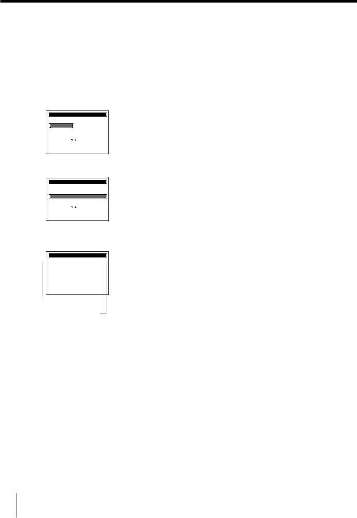
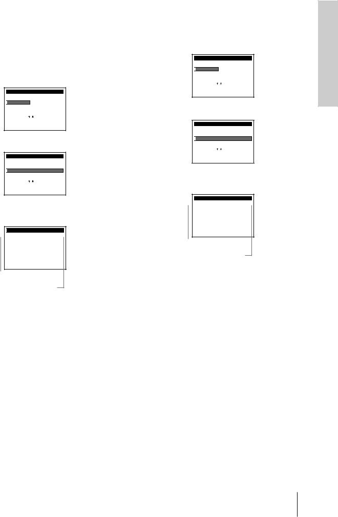
Hookup 1: VCR Plus + channel setup
1 Find the VCR Plus+ Channel Listing in your program guide. For details, see page 43.
2 If the channels in the program guide are different from the channels that you actually use on your TV, set the channels that are different as follows. For details, see page 44.
1 Press MENU and select VHS MENU.
MENU
SOUND SET

 VHS MENU
SELECT |
: |
|
|
|
SET |
: |
EXECUTE |
||
QUIT |
: |
MENU |
|
|
2 Select SET VCR Plus+ CHANNELS.
MENU
TIMER SET / CHECK
TUNER PRESET
CLOCK SET

 SET VCR Plus+ CHANNELS
CABLE BOX CONTROL
ADVANCED OPTIONS
SELECT |
: |
|
|
|
SET |
: |
EXECUTE |
||
QUIT |
: |
MENU |
|
|
3Enter the program guide channel, then the channel you use on your TV.
SET VCR Plus+ CHANNELS
|
GUIDE |
CH TV |
|
CH |
|
||||
|
|
|
|||||||
|
|
|
2 5 |
|
– |
1 |
5 |
|
|
Pu s h |
|
k e y s t o |
|
s e t |
|||||
0 – 9 |
|
|
|||||||
P r o g r |
a m |
|
GUIDE CH |
|
|
|
|
||
O r, p u s h |
|
|
|
t o s e e |
|||||
|
EXECUTE |
|
|||||||
VCR Plus+ CHANNEL LIST
Program guide channel
Your actual TV channel
4 Press EXECUTE.
Started Getting
Getting Started 15
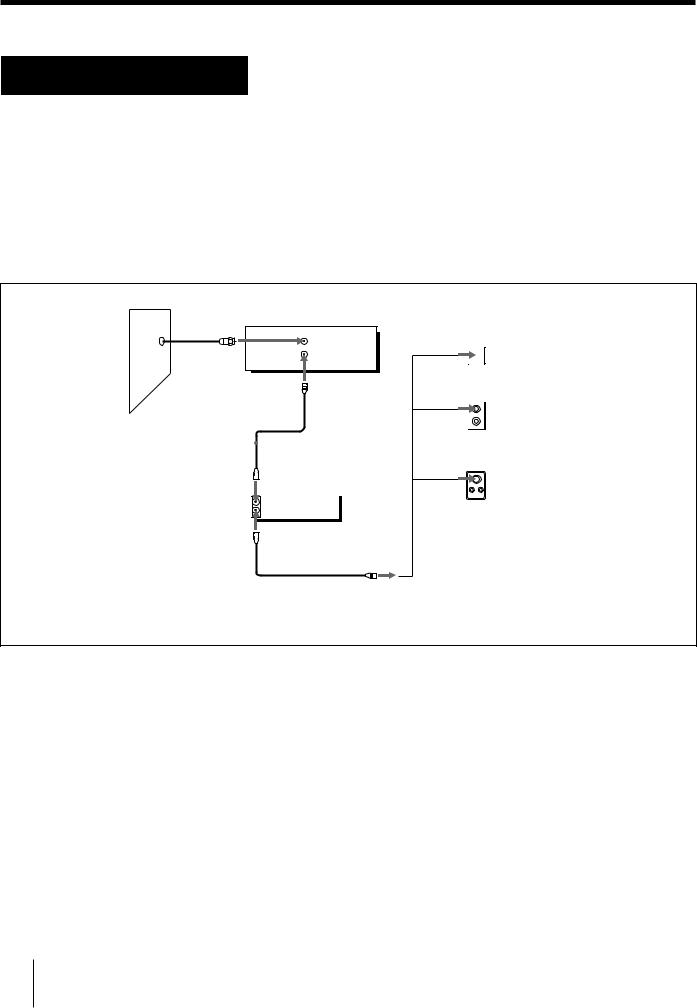
Step 5 TV antenna or cable hookups (continued)
Hookup 2
No cable box, or incompatible cable box with only a few scrambled channels
Recommended use
Use this hookup if you do not have a cable box. Also use this hookup if your cable company cannot supply a cable box that is compatible with the VCR’s cable box control feature, and your cable system scrambles only a few channels.
What you can do with this hookup
• Record any unscrambled channel by selecting the channel on the VCR
What you can’t do
• Record scrambled channels that require a cable box
Wall |
VCR |
|
VHF/UHF |
||
|
||
|
IN |
|
|
OUT |
Connect this cable |
|
|
|
|
|
|
|
|
|
||
directly to your TV if |
|
|
|
||
you don't have a |
|
|
|
||
cable box. |
|
|
Cable box |
||
|
|
||||
|
|
|
|
|
IN |
|
|
|
|
|
OUT |
|
|
|
|
|
|
|
|
|
|
|
|
|
|
|
|
|
|
Rear of TV
VHF/UHF
 A Match the type of connector on or your TV: A, B, or
VHF C.
B |
For connector |
|
types B and C, no |
UHF |
UHF connection |
or |
is required. |
VHF |
|
C |
|
UHF |
|
16 Getting Started

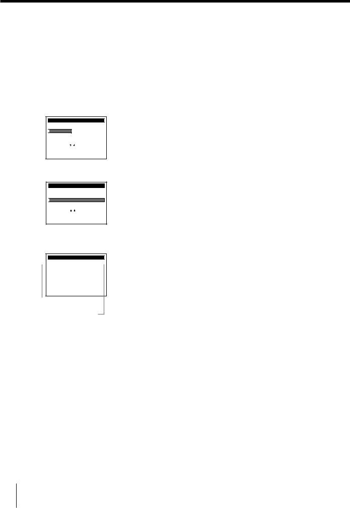
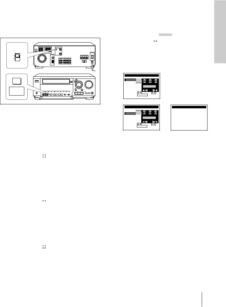
Hookup 2: VCR setup
1 Set the RF UNIT switch to CH 3 or CH 4, whichever channel is not used in your area. If both are used, set the switch to either channel.
For details, see page 92.
If you made V connections (from page 12), you can skip this step.
RF UNIT |
CH3 |
CH4 |
EASY |
SET UP |
2 Press EASY SET UP on the VCR.
1The CLOCK SET menu appears. Set the date and time and press EXECUTE. For details, see page 33.
|
|
|
|
|
|
|
|
|
|
SET UP |
|
|
CLOCK SET |
|
|||
|
|
|
|
|
||||
|
|
1 |
/ 1 / 1 9 9 7 WED 1 2 : 0 0 AM |
|
||||
|
SELECT |
: |
|
|
|
|
||
|
|
|
|
|||||
|
SET |
: |
|
|
|
|
||
|
NEXT |
: |
EXECUTE |
|
|
|||
|
|
|
|
|
|
|
|
|
2The CABLE BOX CONTROL menu appears. Select OFF and press EXECUTE. For details, see page 35.
|
|
|
|
|
|
|
|
|
|
SET UP |
|
|
CABLE BOX |
|
|||
|
CABLE BOX CONTROL |
|
|
|
||||
|
|
CABLE MOUSE |
ON |
OFF |
|
|||
|
SET |
: |
|
|
|
|
|
|
|
|
|
|
|
|
|||
|
NEXT |
: |
EXECUTE |
|
|
|
||
|
|
|
|
|
|
|
|
|
3The TUNER PRESET menu appears. Set ANTENNA/ CABLE to CABLE and press EXECUTE. For details, see page 39.
|
|
|
|
|
|
|
|
|
|
|
SET UP |
|
|
|
TUNER PRESET |
|
|||
|
ANTENNA / CABLE |
|
|||||||
|
|
|
|
|
|
|
|
|
|
|
|
ANT |
|
CABLE |
|
|
|
||
|
SELECT |
: |
|
|
|
|
|
|
|
|
|
|
|
|
|
|
|
||
|
NEXT |
: |
EXECUTE |
|
|
||||
|
CANCEL |
: |
EASY SET UP |
|
|||||
|
|
|
|
|
|
|
|
|
|
4 The AUTO PRESET starts.
|
|
|
|
|
SET UP |
TUNER PRESET |
|
|
AUTO PRESET |
|
|
|
|
EXECUTING |
|
|
P l e a s e |
wa i t |
|
|
|
|
|
5After completing AUTO PRESET, the CENTER MODE selection menu appears.
Select the center mode, and press EXECUTE. For details, see page 30.
|
|
|
|
|
|
|
|
SET UP |
|
|
SOUND SET |
|
|
|
CENTER MODE |
|
||||
|
|
|
|
NORMAL |
|
|
|
SET |
: |
|
|
|
|
|
|
|
|
|
||
|
NEXT |
: |
EXECUTE |
|
|
|
|
|
|
|
|
|
|
6The TEST TONE selection menu appears.
Set the volume of the center and rear speakers and press EXECUTE.
For details, see page 31.
SET UP |
|
SOUND SET |
|
TEST TONE |
+ 5 dB |
|
|
CENTER |
|
|
|
REAR |
|
– 15dB |
|
|
|
TEST TONE |
|
SELECT |
: |
SET |
: |
END |
: |
EXECUTE |
|
SET UP |
|
SOUND SET |
|
|
TEST TONE |
+ 5 dB |
|
|
|
CENTER |
|
|
|
|
REAR |
|
– 5 dB |
|
/ |
|
|
TEST TONE |
||
SELECT |
: |
SET |
: |
|
END |
: |
EXECUTE |
|
|
SET UP
SET UP i s d o n e
.
Normal display
Started Getting
Getting Started 17
Step 5 TV antenna or cable hookups (continued)
Hookup 2: VCR Plus+ channel setup
1 Find the VCR Plus+ Channel Listing in your program guide. For details, see page 43.
2 If the channels in the program guide are different from the channels that you actually use on your TV, set the channels that are different as follows. For details, see page 44.
1 Press MENU and select VHS MENU.
MENU
SOUND SET

 VHS MENU
SELECT |
: |
|
|
|
SET |
: |
EXECUTE |
||
QUIT |
: |
MENU |
|
|
2 Select SET VCR Plus+ CHANNELS.
MENU
TIMER SET / CHECK
TUNER PRESET
CLOCK SET

 SET VCR Plus+ CHANNELS
CABLE BOX CONTROL
ADVANCED OPTIONS
SELECT |
: |
|
|
|
SET |
: |
EXECUTE |
||
QUIT |
: |
MENU |
|
|
3Enter the program guide channel, then the channel you use on your TV.
SET VCR Plus+ CHANNELS
|
GUIDE |
CH TV |
|
CH |
|
||||
|
|
|
|||||||
|
|
|
2 5 |
|
– |
1 |
5 |
|
|
Pu s h |
|
k e y s t o |
|
s e t |
|||||
0 – 9 |
|
|
|||||||
P r o g r |
a m |
|
GUIDE CH |
|
|
|
|
||
O r, p u s h |
|
|
|
t o s e e |
|||||
|
EXECUTE |
|
|||||||
VCR Plus+ CHANNEL LIST
Program guide channel
Your actual TV channel
4 Press EXECUTE.
18 Getting Started

Hookup 3
Antenna hookup
Make the following connections if you’re using an antenna (if you don’t have cable TV).
AUse this hookup if you’re using:
•VHF/UHF antenna (you get channels 2–13 and channels 14 and higher)
•UHF-only antenna (you get channels 14 and higher)
•Separate VHF and UHF antennas
VCR
VHF/UHF
IN
OUT
|
Rear of TV |
|
|
|
VHF/UHF |
|
|
|
A Match the type of |
||
or |
|
connector on your |
|
VHF |
TV: A, B, or C. |
||
|
|||
|
|
||
|
B |
|
|
(not supplied) UHF |
|
||
or |
|
|
|
VHF 


 C
C
(not supplied)
UHF
Started Getting
BUse this hookup if you’re using a VHF-only antenna
(you get channels 2–13 only)
VCR
VHF/UHF
IN
OUT
Rear of TV
VHF/UHF

 A
A
or
VHF

 B
B
UHF
or
VHF
 C
C
UHF
Match the type of connector on your TV: A, B, or C.
For connector types B and C, no UHF connection is required.
If you cannot connect your antenna cable to the VCR directly
If your antenna cable is a flat cable (300-ohm twin lead cable), attach an external antenna connector (not supplied) so you can connect the cable to the VHF/UHF IN connector. If you have separate cables for VHF and UHF antennas, you should use a U/V band mixer (not supplied). For details, see page 92.
Getting Started 19
Step 5 TV antenna or cable hookups (continued)
Hookup 3: VCR setup
1 Set the RF UNIT switch to CH 3 or CH 4, whichever channel is not used in your area. If both are used, set the switch to either channel.
For details, see page 92. If you made V connection (from page 12), you can skip this step.
4 The AUTO PRESET starts.
|
|
|
|
|
SET UP |
TUNER PRESET |
|
|
AUTO PRESET |
|
|
|
|
EXECUTING |
|
|
P l e a s e |
wa i t |
|
|
|
|
|
RF UNIT |
CH3 |
CH4 |
EASY |
SET UP |
2 Press EASY SET UP on the VCR. |
1The CLOCK SET menu appears. Set the date and time and press EXECUTE. For details, see page 33.
|
|
|
|
|
|
|
|
|
|
SET UP |
|
|
CLOCK SET |
|
|||
|
|
|
|
|
||||
|
|
1 |
/ 1 / 1 9 9 7 WED 1 2 : 0 0 AM |
|
||||
|
SELECT |
: |
|
|
|
|
||
|
|
|
|
|||||
|
SET |
: |
|
|
|
|
||
|
NEXT |
: |
EXECUTE |
|
|
|||
|
|
|
|
|
|
|
|
|
2The CABLE BOX CONTROL menu appears. Select OFF and press EXECUTE. For details, see page 35.
|
|
|
|
|
|
|
|
|
|
SET UP |
|
|
CABLE BOX |
|
|||
|
CABLE BOX CONTROL |
|
|
|
||||
|
|
CABLE MOUSE |
ON |
OFF |
|
|||
|
SET |
: |
|
|
|
|
|
|
|
|
|
|
|
|
|||
|
NEXT |
: |
EXECUTE |
|
|
|
||
|
|
|
|
|
|
|
|
|
3The TUNER PRESET menu appears. Set ANTENNA/ CABLE to ANT and press EXECUTE. For details, see page 39.
5After completing AUTO PRESET, the CENTER MODE selection menu appears.
Select the center mode, and press EXECUTE. For details, see page 30.
|
|
|
|
|
|
|
|
SET UP |
|
|
SOUND SET |
|
|
|
CENTER MODE |
|
||||
|
|
|
|
NORMAL |
|
|
|
SET |
: |
|
|
|
|
|
|
|
|
|
||
|
NEXT |
: |
EXECUTE |
|
|
|
|
|
|
|
|
|
|
6The TEST TONE selection menu appears.
Set the volume of the center and rear speakers and press EXECUTE.
For details, see page 31.
SET UP |
SOUND SET |
TEST TONE
CENTER |
|
+ 5 dB |
|
REAR |
|
– 15dB |
|
|
|
TEST TONE |
|
SELECT |
: |
SET |
: |
END |
: |
EXECUTE |
|
SET UP |
|
SOUND SET |
|
|
TEST TONE |
+ 5 dB |
|
|
|
CENTER |
|
|
|
|
REAR |
|
– 5 dB |
|
/ |
|
|
TEST TONE |
||
SELECT |
: |
SET |
: |
|
END |
: |
EXECUTE |
|
|
SET UP
SET UP i s d o n e
.
Normal display
|
|
|
|
|
|
|
|
|
|
SET UP |
|
|
|
TUNER PRESET |
|
||
|
ANTENNA / CABLE |
|
||||||
|
|
|
|
|
|
|
|
|
|
|
ANT |
|
CABLE |
|
|
|
|
|
SELECT |
: |
|
|
|
|
|
|
|
|
|
|
|
|
|
||
|
SET |
: |
|
|
|
|
|
|
|
CANCEL |
: |
EASY SET UP |
|
||||
|
|
|
|
|
|
|
|
|
20 Getting Started
Hookup 3: VCR Plus+ channel setup
1 Find the VCR Plus+ Channel Listing in your program guide. For details, see page 43.
2 If the channels in the program guide are different from the channels that you actually use on your TV, set the channels that are different as follows. For details, see page 44.
1 Press MENU and select VHS MENU.
MENU
SOUND SET

 VHS MENU
SELECT |
: |
|
|
|
SET |
: |
EXECUTE |
||
QUIT |
: |
MENU |
|
|
2 Select SET VCR Plus+ CHANNELS.
MENU
TIMER SET / CHECK
TUNER PRESET
CLOCK SET

 SET VCR Plus+ CHANNELS
CABLE BOX CONTROL
ADVANCED OPTIONS
SELECT |
: |
|
|
|
SET |
: |
EXECUTE |
||
QUIT |
: |
MENU |
|
|
3Enter the program guide channel, then the channel you use on your TV.
SET VCR Plus+ CHANNELS
|
GUIDE |
CH TV |
|
CH |
|
||||
|
|
|
|||||||
|
|
|
2 5 |
|
– |
1 |
5 |
|
|
Pu s h |
|
k e y s t o |
|
s e t |
|||||
0 – 9 |
|
|
|||||||
P r o g r |
a m |
|
GUIDE CH |
|
|
|
|
||
O r, p u s h |
|
|
|
t o s e e |
|||||
|
EXECUTE |
|
|||||||
VCR Plus+ CHANNEL LIST
Program guide channel
Your actual TV channel
4 Press EXECUTE.
Started Getting
Getting Started 21
Step 5 TV antenna or cable hookups (continued)
Hookup 4
Incompatible cable box with many scrambled channels
Recommended use
Use this hookup if your cable company cannot supply a cable box that is compatible with the VCR’s cable box control feature, and your cable system scrambles all or most channels.
What you can do with this hookup
• Record any channel by selecting the channel on the cable box
What you can’t do
•Record with the cable box turned off
•Record one channel while watching another channel
•Select channels directly on the VCR
Wall |
Cable box |
IN |
OUT |
VCR
VHF/UHF
IN
OUT
|
Rear of TV |
||
|
VHF/UHF |
||
|
|
|
A Match the type of |
|
|
|
connector on your |
|
|
|
|
or |
|
|
TV: A, B, or C. |
|
|
|
|
|
VHF |
|
|
B |
For connector |
|
|
types B and C, no |
or |
UHF |
UHF connection |
|
is required. |
|
|
|
|
|
VHF |
|
|
C |
|
|
UHF |
|
22 Getting Started
Hookup 4: VCR setup
1 Set the RF UNIT switch to CH 3 or CH 4, whichever channel is not used in your area. If both are used, set the switch to either channel.
For details, see page 92. If you made V connection (from page 12), you can skip this step.
RF UNIT |
CH3 |
CH4 |
EASY |
SET UP |
2 Turn on your cable box. |
3 Press EASY SET UP on the VCR. |
1The CLOCK SET menu appears. Set date and time and press EXECUTE. For details, see page 33.
|
|
|
|
|
|
|
|
|
|
SET UP |
|
|
CLOCK SET |
|
|||
|
|
|
|
|
||||
|
|
1 |
/ 1 / 1 9 9 7 WED 1 2 : 0 0 AM |
|
||||
|
SELECT |
: |
|
|
|
|
||
|
|
|
|
|||||
|
SET |
: |
|
|
|
|
||
|
NEXT |
: |
EXECUTE |
|
|
|||
|
|
|
|
|
|
|
|
|
2The CABLE BOX CONTROL menu appears. Select OFF and press EXECUTE. For details, see page 35.
|
|
|
|
|
|
|
|
|
|
SET UP |
|
|
CABLE BOX |
|
|||
|
CABLE BOX CONTROL |
|
|
|
||||
|
|
CABLE MOUSE |
ON |
OFF |
|
|||
|
SET |
: |
|
|
|
|
|
|
|
|
|
|
|
|
|||
|
NEXT |
: |
EXECUTE |
|
|
|
||
|
|
|
|
|
|
|
|
|
3The TUNER PRESET menu appears. Set ANTENNA/ CABLE to ANT and press EXECUTE. For details, see page 39.
|
|
|
|
|
|
|
|
|
|
SET UP |
|
|
|
TUNER PRESET |
|
||
|
ANTENNA / CABLE |
|
||||||
|
|
|
|
|
|
|
|
|
|
|
ANT |
|
CABLE |
|
|
|
|
|
SELECT |
: |
|
|
|
|
|
|
|
|
|
|
|
|
|
||
|
SET |
: |
|
|
|
|
|
|
|
CANCEL |
: |
EASY SET UP |
|
||||
|
|
|
|
|
|
|
|
|
4 The AUTO PRESET starts.
|
|
|
|
|
SET UP |
TUNER PRESET |
|
|
AUTO PRESET |
|
|
|
|
EXECUTING |
|
|
P l e a s e |
wa i t |
|
|
|
|
|
5 After completing AUTO PRESET, the CENTER MODE |
|
||||||||
selection menu appears. |
|
||||||||
Select the center mode, and press EXECUTE. |
|
||||||||
For details, see page 30. |
Getting |
||||||||
|
|
|
|
|
|
|
|
|
|
|
|
SET UP |
|
|
SOUND SET |
|
|
||
|
|
CENTER MODE |
|
|
|
||||
|
|
|
|
|
NORMAL |
|
|
Started |
|
|
|
|
|
|
|
|
|
||
|
|
SET |
: |
|
|
|
|
|
|
|
|
|
|
|
|
|
|
||
|
|
NEXT |
: |
EXECUTE |
|
|
|
|
|
|
|
|
|
|
|
|
|
|
|
6The TEST TONE selection menu appears.
Set the volume of the center and rear speakers and press EXECUTE.
For details, see page 31.
SET UP |
|
SOUND SET |
|
TEST TONE |
+ 5 dB |
|
|
CENTER |
|
|
|
REAR |
|
– 15dB |
|
|
|
TEST TONE |
|
SELECT |
: |
SET |
: |
END |
: |
EXECUTE |
|
SET UP |
|
|
SOUND SET |
|
TEST TONE |
+ 5 dB |
|
|
|
CENTER |
|
|
|
|
REAR |
|
– 5 dB |
TEST TONE |
/ |
SELECT |
: |
|
SET : |
|
END |
: |
EXECUTE |
|
|
SET UP
SET UP i s d o n e
.
Normal display
Getting Started 23
Step 5 TV antenna or cable hookups (continued)
Hookup 4: VCR Plus+ channel setup
1 Find the VCR Plus+ Channel Listing in your program guide. For details, see page 43.
2 Enter all the channels you want to record and the cable box output channel (usually 2, 3, or 4). For details, see page 44.
1 Press MENU and select VHS MENU.
MENU
SOUND SET

 VHS MENU
SELECT |
: |
|
|
|
SET |
: |
EXECUTE |
||
QUIT |
: |
MENU |
|
|
2 Select SET VCR Plus+ CHANNELS.
MENU
TIMER SET / CHECK
TUNER PRESET
CLOCK SET

 SET VCR Plus+ CHANNELS
CABLE BOX CONTROL
ADVANCED OPTIONS
SELECT |
: |
|
|
|
SET |
: |
EXECUTE |
||
QUIT |
: |
MENU |
|
|
3Enter the program guide channel, then the cable box output channel.
SET VCR Plus+ CHANNELS
|
GUIDE |
CH TV |
CH |
|
||||
|
|
|||||||
|
|
|
3 3 |
|
– |
3 |
|
|
Pu s h |
|
k e y s t o s e t |
||||||
0 – 9 |
|
|||||||
P r o g r |
a m |
|
GUIDE CH |
|
|
|
||
O r, p u s h |
|
|
t o s e e |
|||||
|
EXECUTE |
|||||||
VCR Plus+ CHANNEL LIST
Program guide channel
Cable box output channel
4 Press EXECUTE.
24 Getting Started

Hookup 5
DSS (Digital Satellite System) receiver
Recommended use
Use this hookup if you have a DSS receiver. It allows the VCR’s cable box control feature to control the channel on the DSS receiver, simplifying the recording process. A list of compatible DSS receivers is on page 37.
DSS (Digital Satellite System) is a satellite broadcast that provides superior digital-quality video and crisp digital-quality audio. A variety of program packages are available through your program providers. It also has program guides that are sorted by program categories.
What you can do with this hookup
•Record any channels using the VCR’s cable box control feature to select channels on the DSS receiver.
What you can’t do
•Record with the DSS receiver turned off
•Record any channels from cable or an antenna (To record channels from cable or an antenna, turn off the cable box control feature.)
•Use a cable box
•Record programs with VCR Plus+
Started Getting
Rear of TV
VHF/UHF
Wall
|
|
|
or |
or |
VCR |
|
|
|
|
||
VHF/UHF |
AUDIO |
VIDEO |
or |
IN |
LINE |
||
LINE |
IN |
||
|
IN |
|
|
OUT |
|
CONTROL S OUT |
|
AMatch the type of connector on your
VHF |
TV: A,B or C |
|
|
B |
For connector |
|
types |
|
B and C, no UHF |
|
connection is |
VHF |
required. |
C |
|
Cable
 Mouse (not supplied)
VHF/UHF
LINE IN
OUT
OUT
AUDIO VIDEO
UHF
Positioning the Cable Mouse
Place the Cable Mouse so that it hangs out over the DSS receiver front.
DSS receiver
Side view
Getting Started 25
Step 5 TV antenna or cable hookups (continued)
Hookup 5: VCR setup
1 Set the RF UNIT switch to CH 3 or CH4, whichever channel is not used in your area. If both are used, set the switch to either channel.
For details, see page 92. If you made V connection (from page 12), you can skip this step.
RF UNIT |
CH3 |
CH4 |
EASY |
SET UP |
2 Turn on your DSS receiver. |
3 Press EASY SET UP on the VCR. |
1The CLOCK SET menu appears. Set the date and time and press EXECUTE. For details, see page 33.
|
|
|
|
|
|
|
|
|
|
SET UP |
|
|
CLOCK SET |
|
|||
|
|
|
|
|
||||
|
|
1 |
/ 1 / 1 9 9 7 WED 1 2 : 0 0 AM |
|
||||
|
SELECT |
: |
|
|
|
|
||
|
|
|
|
|||||
|
SET |
: |
|
|
|
|
||
|
NEXT |
: |
EXECUTE |
|
|
|||
|
|
|
|
|
|
|
|
|
2The CABLE BOX CONTROL menu appears. Select ON. For details, see page 35.
|
|
|
|
|
|
|
|
|
|
SET UP |
|
|
|
CABLE BOX |
|
||
|
CABLE BOX CONTROL |
|
||||||
|
CABLE MOUSE |
|
ON |
OFF |
|
|||
|
BOX CODE NO. |
|
––– |
|
|
|||
|
BOX OUTPUT CH |
|
CH3 |
|
||||
|
SELECT |
: |
|
|
|
|
|
|
|
|
|
|
|
|
|
||
|
SET |
: |
0 – 9 |
|
k e y s |
|||
|
|
|
|
|
|
|
|
|
3Enter your DSS receiver code number and press CURSOR..
For details, see page 35.
|
|
|
|
|
|
|
|
|
|
SET UP |
|
|
|
CABLE BOX |
|
||
|
CABLE BOX CONTROL |
|
||||||
|
CABLE MOUSE |
ON |
OFF |
|
||||
|
BOX CODE NO. |
650 |
|
|
||||
|
BOX OUTPUT CH |
CH3 |
|
|||||
|
SELECT |
: |
|
|
|
|
|
|
|
|
|
|
|
|
|
||
|
SET |
: |
|
|
|
|
|
|
|
NEXT |
: |
EXECUTE |
|
||||
|
|
|
|
|
|
|
|
|
4Set your DSS receiver output channel (BOX OUTPUT CH) to LINE and press EXECUTE.
|
|
|
|
|
|
|
|
|
|
SET UP |
|
|
|
CABLE BOX |
|
||
|
CABLE BOX CONTROL |
|
||||||
|
CABLE MOUSE |
ON |
OFF |
|
||||
|
BOX CODE NO. |
650 |
|
|
||||
|
BOX OUTPUT CH |
LINE |
|
|||||
|
SELECT |
: |
|
|
|
|
|
|
|
|
|
|
|
|
|
||
|
SET |
: |
|
|
|
|
|
|
|
NEXT |
: |
EXECUTE |
|
||||
|
|
|
|
|
|
|
|
|
5The CENTER MODE selection menu appears. Select the center mode and press EXECUTE. For details, see page 30.
|
|
|
|
|
|
|
|
SET UP |
|
|
SOUND SET |
|
|
|
CENTER MODE |
|
||||
|
|
|
|
NORMAL |
|
|
|
SET |
: |
|
|
|
|
|
|
|
|
|
||
|
NEXT |
: |
EXECUTE |
|
|
|
|
|
|
|
|
|
|
6The TEST TONE selection menu appears.
Set the volume of the center and rear speakers and press EXECUTE.
For details, see page 31.
SET UP |
|
SOUND SET |
|
TEST TONE |
+ 5 dB |
|
|
CENTER |
|
|
|
REAR |
|
– 15dB |
|
|
|
TEST TONE |
|
SELECT |
: |
SET |
: |
END |
: |
EXECUTE |
|
SET UP |
|
SOUND SET |
|
|
TEST TONE |
+ 5 dB |
|
|
|
CENTER |
|
|
|
|
REAR |
|
– 5 dB |
|
|
|
|
TEST TONE |
/ |
|
SELECT |
: |
SET |
: |
|
END |
: |
EXECUTE |
|
|
SET UP
SET UP i s d o n e
.
Normal display
Notes
To successfully record a program from the DSS receiver, proceed as follows:
•Leave the DSS receiver on all the time.
•Turn off the display (menu screen, channel number, etc.) of the DSS receiver.
•To record or receive locked channels, unlock the channel before the VCR starts recording.
•To set pay-per-view programs in the timer setting, order the pay-per-view program before the VCR starts recording.
•Some programs are copy protected. You cannot record these programs.
26 Getting Started

Hookup 6
Incompatible cable box with only a few scrambled channels, using an A/B switch
Recommended use
By using an A/B switch (not supplied), this hookup allows you to record both scrambled and unscrambled channels conveniently.
What you can do with this hookup
•Record any unscrambled channel by selecting the channel directly on the VCR (the A/B switch is set to A)
•Record any scrambled channel by selecting the channel on the cable box (the A/B switch is set to B)
What you can’t do
•Record one scrambled channel while watching another channel (the A/B switch is set to B)
Started Getting
Wall |
Splitter |
Cable box |
Rear of TV |
(not supplied) |
|
||
|
|
VHF/UHF |
|
|
IN |
|
|
|
OUT |
|
A |
|
|
|
|
|
|
|
or |
|
|
|
VHF |
A/B switch
A 


 B
B
VCR
VHF/UHF
IN
OUT
B
UHF
or
VHF
C
UHF
Match the type of connector on your TV: A, B, or C.
For connector types B and C, no UHF connection is required.
Getting Started 27

Step 5 TV antenna or cable hookups (continued)
Hookup 6: VCR setup
1 Set the RF UNIT switch to CH 3 or CH 4, whichever channel is not used in your area. If both are used, set the switch to either channel.
For details, see page 92. If you made V connection (from page 12), you can skip this step.
4 The AUTO PRESET starts.
|
|
|
|
|
SET UP |
TUNER PRESET |
|
|
AUTO PRESET |
|
|
|
|
EXECUTING |
|
|
P l e a s e |
wa i t |
|
|
|
|
|
RF UNIT |
CH3 |
CH4 |
EASY |
SET UP |
2 Set the A/B switch to “A.”
3 Press EASY SET UP on the VCR.
1The CLOCK SET menu appears. Set the date and time and press EXECUTE. For details, see page 33.
5After completing AUTO PRESET, the CENTER MODE selection menu appears.
Select the center mode, and press EXECUTE. For details, see page 30.
|
|
|
|
|
|
|
|
SET UP |
|
|
SOUND SET |
|
|
|
CENTER MODE |
|
||||
|
|
|
|
NORMAL |
|
|
|
SET |
: |
|
|
|
|
|
|
|
|
|
||
|
NEXT |
: |
EXECUTE |
|
|
|
|
|
|
|
|
|
|
6The TEST TONE selection menu appears.
Set the volume of the center and rear speakers and press EXECUTE.
For details, see page 31.
SET UP |
|
SOUND SET |
|
TEST TONE |
+ 5 dB |
|
|
CENTER |
|
|
|
REAR |
|
– 15dB |
|
|
|
TEST TONE |
|
SELECT |
: |
SET |
: |
END |
: |
EXECUTE |
|
|
|
|
|
|
|
|
|
|
|
SET UP |
|
|
CLOCK SET |
|
|||
|
|
|
|
|
||||
|
|
1 |
/ 1 / 1 9 9 7 WED 1 2 : 0 0 AM |
|
||||
|
SELECT |
: |
|
|
|
|
||
|
|
|
|
|||||
|
SET |
: |
|
|
|
|
||
|
NEXT |
: |
EXECUTE |
|
|
|||
|
|
|
|
|
|
|
|
|
SET UP |
|
|
SOUND SET |
|
TEST TONE |
+ 5 dB |
|
|
|
CENTER |
|
|
|
|
REAR |
|
– 5 dB |
TEST TONE |
/ |
SELECT |
: |
|
SET : |
|
END |
: |
EXECUTE |
|
|
SET UP
SET UP i s d o n e
2 The CABLE BOX CONTROL menu appears. Select |
. |
OFF and press EXECUTE. For details, see page 35. |
Normal display |
|
|
|
|
|
|
|
|
|
|
SET UP |
|
|
CABLE BOX |
|
|||
|
CABLE BOX CONTROL |
|
|
|
||||
|
|
CABLE MOUSE |
ON |
OFF |
|
|||
|
SET |
: |
|
|
|
|
|
|
|
|
|
|
|
|
|||
|
NEXT |
: |
EXECUTE |
|
|
|
||
|
|
|
|
|
|
|
|
|
3The TUNER PRESET menu appears. Set ANTENNA/ CABLE to CABLE and press EXECUTE. For details, see page 39.
|
|
|
|
|
|
|
|
|
|
|
SET UP |
|
|
|
TUNER PRESET |
|
|||
|
ANTENNA / CABLE |
|
|||||||
|
|
|
|
|
|
|
|
|
|
|
|
ANT |
|
CABLE |
|
|
|
||
|
SELECT |
: |
|
|
|
|
|
|
|
|
|
|
|
|
|
|
|
||
|
NEXT |
: |
EXECUTE |
|
|
||||
|
CANCEL |
: |
EASY SET UP |
|
|||||
|
|
|
|
|
|
|
|
|
|
28 Getting Started
4 Preset the cable box output channel (usually 2, 3 or 4). For details, see page 35.
1Press MENU. Then press CURSOR >/.to move the cursor (I) to VHS MENU, and press EXECUTE.
2 Select TUNER PRESET.
MENU
TIMER SET / CHECK

 TUNER PRESET
CLOCK SET
SET VCR Plus+ CHANNELS
CABLE BOX CONTROL
ADVANCED OPTIONS
SELECT |
: |
|
|
|
SET |
: |
EXECUTE |
||
QUIT |
: |
MENU |
|
|
3Enter the cable box output channel. Set MANUAL SET to ADD and press EXECUTE.
|
|
|
|
|
|
|
|
|
|
TUNER PRESET |
|
|
|
CH3 |
|
||
|
ANTENNA / CABLE |
|
|
|
|
|
||
|
ANT |
CABLE |
|
|||||
|
AUTO PRESET |
|
|
|
|
|
|
|
|
MANUAL SET |
|
|
ADD |
ERASE |
|
||
|
AFT |
|
|
ON |
OFF |
|
||
|
FINE TUNING |
|
|
|
|
|
|
|
|
SELECT CH |
: |
|
|
|
|||
|
0 – 9 |
ENTER |
|
|||||
|
ADD / ERASE |
: |
|
|
|
|
|
|
|
|
|
|
|
|
|
|
|
Hookup 6: VCR Plus+ channel setup
1 Find the VCR Plus+ Channel Listing in your program guide. For details, see page 43.
2 For unscrambled channels, if the channels in the program guide are different from the channels that you actually use on your TV, set the channels that are different as follows. For details, see page 44.
1 Press MENU and select VHS MENU.
MENU
SOUND SET

 VHS MENU
SELECT |
: |
|
|
|
SET |
: |
EXECUTE |
||
QUIT |
: |
MENU |
|
|
2 Select SET VCR Plus+ CHANNELS.
MENU
TIMER SET / CHECK
TUNER PRESET
CLOCK SET

 SET VCR Plus+ CHANNELS
CABLE BOX CONTROL
ADVANCED OPTIONS
SELECT |
: |
|
|
|
SET |
: |
EXECUTE |
||
QUIT |
: |
MENU |
|
|
3Enter the program guide channel, then the channel you use on your TV.
SET VCR Plus+ CHANNELS
|
GUIDE |
CH TV |
|
CH |
|
||||
|
|
|
|||||||
|
|
|
2 5 |
|
– |
1 |
5 |
|
|
Pu s h |
|
k e y s t o |
|
s e t |
|||||
0 – 9 |
|
|
|||||||
P r o g r |
a m |
|
GUIDE CH |
|
|
|
|
||
O r, p u s h |
|
|
|
t o s e e |
|||||
|
EXECUTE |
|
|||||||
VCR Plus+ CHANNEL LIST
Program guide channel
Your actual TV channel
4 Press EXECUTE.
3 For scrambled channels, enter all the scambled channels you want to record and the cable box output channel (usually 2, 3, or 4). For details, see page 44.
1 Press MENU and select VHS MENU.
MENU
SOUND SET

 VHS MENU
SELECT |
: |
|
|
|
SET |
: |
EXECUTE |
||
QUIT |
: |
MENU |
|
|
2 Select SET VCR Plus+ CHANNELS.
MENU
TIMER SET / CHECK
TUNER PRESET
CLOCK SET

 SET VCR Plus+ CHANNELS
CABLE BOX CONTROL
ADVANCED OPTIONS
SELECT |
: |
|
|
|
SET |
: |
EXECUTE |
||
QUIT |
: |
MENU |
|
|
3Enter the program guide channel, then the cable box output channel.
SET VCR Plus+ CHANNELS
|
GUIDE |
CH TV |
CH |
|
||||
|
|
|||||||
|
|
|
2 5 |
|
– |
3 |
|
|
Pu s h |
|
k e y s t o s e t |
||||||
0 – 9 |
|
|||||||
P r o g r |
a m |
|
GUIDE CH |
|
|
|
||
O r, p u s h |
|
|
t o s e e |
|||||
|
EXECUTE |
|||||||
VCR Plus+ CHANNEL LIST
Program guide channel
Cable box output channel
Started Getting
Getting Started 29
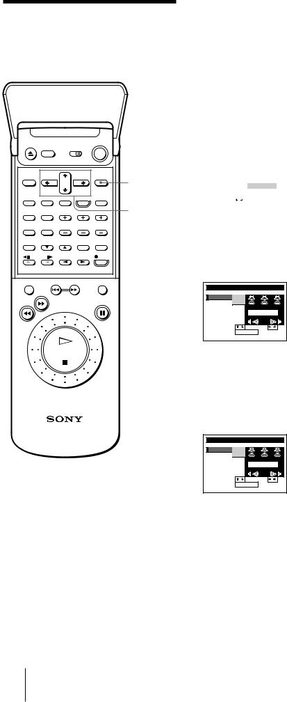
Adjusting the SOUND SET with EASY SET UP
You can set the center mode for the PROLOGIC and THEATER sound fields, and the relative volume level of the center and rear speakers for the PROLOGIC sound field with EASY SET UP. (For sound field explanations, see page 75.)
EXECUTE
CURSOR
>/./?//
1Complete each operation other than SOUND SET with EASY SET UP referring to pages 13 to 30.
2After the CENTER MODE selection menu appears, press ?//to select the center mode.
See “Selecting the center mode” on page 32 for details.
|
|
|
|
|
|
|
|
SET UP |
|
|
SOUND SET |
|
|
|
CENTER MODE |
|
||||
|
|
|
|
WIDE |
|
|
|
SET |
: |
|
|
|
|
|
|
|
|
|
||
|
NEXT |
: |
EXECUTE |
|
||
|
|
|
|
|
|
|
3Press EXECUTE.
Each speaker emits the test tone in turn (the speaker emitting the test tone is indicated by the red speaker mark).
Check each speaker’s relative volume balance with the test tones.
SET UP |
|
SOUND SET |
|
CENTER MODE |
|
||
CENTER |
|
0 dB |
|
REAR |
|
0 dB |
|
|
|
TEST TONE |
|
SELECT |
: |
SET |
: |
END |
: |
EXECUTE |
|
4Press CURSOR >/.to move the cursor (I) to CENTER. Then, press CURSOR ?//to increase or decrease the volume of the center
speaker so you have an equal volume balance with the other speakers at your listening position.
If you selected PHANTOM in step 2, skip this step.
This volume adjustment affects only the PROLOGIC sound field.
SET UP |
|
SOUND SET |
|
CENTER MODE |
|
||
CENTER |
|
+8 dB |
|
REAR |
|
0 dB |
|
|
|
TEST TONE |
|
SELECT |
: |
SET |
: |
END |
: |
EXECUTE |
|
30 Getting Started
 Loading...