


 Loading...
HISTORY INFORMATION FOR THE FOLLOWING MANUAL:
SERVICE MANUAL
ORIGINAL MANUAL ISSUE DATE: 5/2016
Version Date Subject
1.05/2016 Original manual issue.
1.16/2016 Add Main Board Replacement Caution Guide at slide 17
Add Power Board Replacement Caution Guide at slide 18
Update LVDS cable picture at slide 20
Add Himeron Countermeasure at slide 28~33
Update tape location at slide 40
Update SW version at slide 44, 46
Add Assembly Parts at slide 50~55
1.28/2016 Add LA1 model
1.39/2016 Add LGD panel model power board P/N at slide 13
Add LGD panel P/N at slide 14
Add Select Panel Type at slide 56
1.49/2016 Renew the description to Stand Bracket at slide 14
Chassis Name :GN2TP
Segment Name : QW
LCD Digital Color TV
9-888-710-05
MODEL LIST
|
|
|
|
|
|
|
|
|
|
|
MODEL |
COLOR |
COMMANDER |
DEST. |
|
MODEL |
COLOR COMMANDER DEST. |
|
|
|
|
|
|||||||
|
|
|
|||||||
|
KDL-55W650D |
Black |
RMT-TX102U |
UC2 |
|
|
|
|
|
|
KDL-55W650D |
Black |
RMT-TX102U |
LA1 |
|
|
|
|
|
|
|
|
|
|
|
|
|
|
|
|
|
|
|
|
|
|
|
|
|
2
KDL-55W650D UC2/LA1

Table of content
Description |
Page |
WARNINGS AND CAUTIONS………………………………………… |
4 |
USE CAUTION WHEN HANDLING THE LCD PANEL…………… |
5 |
SAFETY CHECK-OUT………………………………………………… |
6 |
SELF DIAGNOSIS FUNCTION……………………………………… |
8 |
SERVICE POSITION…………………………………………………… |
9 |
SEC 1. DISASSEMBLY AND PARTS LIST…………………………… |
10 |
1-1. KDL-55W650D …………………………………………………… |
11 |
1-1-1. BASE STAND……………………………………………… |
11 |
1-1-2. REAR COVER ……………………………………………… |
12 |
1-1-3. POWER BOARD, A BOARD AND SPEAKER ………… |
13 |
1-1-4. LCD PANEL, DECO and COVER, BOTTOM ………… |
14 |
1-1-5. MISCELLANEOUS………………………………………… |
15 |
1-2. How to disassemble rear cover [KDL-55W650D]…………….. |
16 |
1-3. Main Board Replacement Caution Guide [KDL-55W650D]……. 17
1-4. Power Board Replacement Caution Guide [KDL-55W650D]……18 1-5. How to disassemble Deco………………………………….………… 19
1-5-1. How to disassemble Deco [KDL-55W650D]……………. |
19 |
1-6. How to disassemble LVDS cable [KDL-55W650D]…………… |
20 |
1-6-1. How to disassemble LVDS cable [KDL-55W650D]……… |
20 |
1-7. How to disassemble IR Board[KDL-55W650D ]………………. |
22 |
1-8. How to ass’y the LED lens [KDL-55W650D]…………………. |
23 |
1-9. How to ass’y the KEY Board[KDL-55W650D]………………… |
24 |
1-10. How to disassembly the Front bezel[KDL-55W650D]………… |
25 |
1-11. How to ass’y the Front bezel[KDL-55W650D]……………………27 1-12 Himeron Countermeasure on panel[KDL-55W650D]…………….28 SEC 2. ADJUSTMENT…………………………………………………….. 34
Description |
Page |
SEC 3. DIAGRAMS AND CHASSIS STRUCTURE………………… |
36 |
3-1. BLOCK DIAGRAM……………………………………………… |
36 |
3-2. CONNECTOR DIAGRAM……………………………………… |
37 |
3-3. CIRCUIT BOARDS LOCATION……………………………… |
38 |
3-4. Tape location……………………………………………………… |
40 |
APPENDIX-1 Trouble analysis flow…………………………………… |
43 |
APPENDIX-2 Software data update…………………………………… |
44 |
APPENDIX-3 Panel Operation Time………………………………….. |
48 |
APPENDIX-4 Edit MODEL NAME and Serial Number…………… |
49 |
APPENDIX-5 Assembly parts…………………………………………. |
50 |
APPENDIX-6 Select Panel Type…………………………………………. 56
3
KDL-55W650D UC2/LA1

WARNINGS AND CAUTIONS - ENGLISH
CAUTION
These servicing instructions are for use by qualified service personnel only.
To reduce the risk of electric shock, do not perform any servicing other than that contained in the operating instructions unless you are qualified to do so.
WARNING!!
An isolation transformer should be used during any service to avoid possible shock hazard, because of live chassis.
The chassis of this receiver is directly connected to the ac power line.
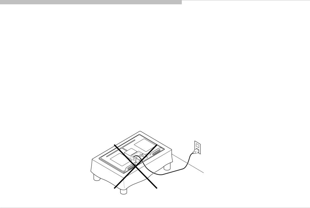
CARRYING THE TV
Be sure to follow these guidelines to protect your property and avoid causing serious injury.
•Carry the TV with an adequate number of people; larger size TVs require two or more people.
•Correct hand placement while carrying the TV is very important for safety and to avoid damages.
SAFETY-RELATED COMPONENT WARNING!!
Components identified by shading and ! mark on the schematic diagrams, exploded views, and in the parts list are critical for safe operation. Replace these components with Sony parts whose part numbers appear as shown in this manual or in supplements published by Sony. Circuit adjustments that are critical for safe operation are identified in this manual. Follow these procedures whenever critical components are replaced or improper operation is suspected.
4
KDL-55W650D UC2/LA1
WARNINGS AND CAUTIONS
USE CAUTION WHEN HANDLING THE LCD PANEL
When repairing the LCD panel, be sure you are grounded by using a wrist band.
When repairing the LCD panel on the wall, the LCD panel must be secured using the 4 mounting holes on the rear cover.
1)Do not press on the panel or frame edge to avoid the risk of electric shock.
2)Do not scratch or press on the panel with any sharp objects.
3)Do not leave the module in high temperatures or in areas of high humidity for an extended period of time.
4)Do not expose the LCD panel to direct sunlight.
5)Avoid contact with water. It may cause a short circuit within the module.
6)Always clean the LCD panel with a soft cloth material.
7)Use care when handling the wires or connectors of the inverter circuit. Damaging the wires may cause a short.
8)Protect the panel from ESD to avoid damaging the electronic circuit (C-MOS).
9)It is recommended not to exceed 1 hour of Power-On nor Burn-in period with LCD panel face down condition, in repair activity. 10)Disconnect the AC power when replacing the parts.(FFC cable etc.).
5
KDL-55W650D UC2/LA1

SAFETY CHECK-OUT
After correcting the original service problem, perform the following safety checks before releasing the set to the customer:
1.Check the area of your repair for unsoldered or poorly soldered connections. Check the entire board surface for solder splashes and bridges.
2.Check the interboard wiring to ensure that no wires are “pinched” or touching high-wattage resistors.
3.Check that all control knobs, shields, covers, ground straps, and mounting hardware have been replaced. Be absolutely certain that you have replaced all the insulators.
4.Look for unauthorized replacement parts, particularly transistors, that were installed during a previous repair. Point them out to the customer and recommend their replacement.
5.Look for parts which, though functioning, show obvious signs of deterioration. Point them out to the customer and recommend their replacement.
6.Check the line cords for cracks and abrasion. Recommend the replacement of any such line cord to the customer.
7.Check the antenna terminals, metal trim, “metallized” knobs, screws, and all other exposed metal parts for AC leakage. Check leakage as described below.
8.For safety reasons, repairing the Power board and/or Inverter board is prohibited.
6
KDL-55W650D UC2/LA1

SAFETY CHECK-OUT
Leakage Test
(To protect electric shock when customer touch the terminal.)
Leakage current can be measured by V: Voltmeter or oscilloscope (r.m.s. or peak reading) Stabilized power supply instrument and isolated voltage transformer:
Use too much current capacity and isolated voltage transformer does not need to use stabilized power supply equipment Specification of RMS volt meter: Input resistance > 1 Mohm, Input capacitance < 200 pF,
Frequency range: 15 Hz – 1MHz (Refer Figure 1). Isolated type volt -meter (FLUKE 8921A etc *1)
*1 Not use FLUKE 8920A that connected to protective earth by diode
#Leakage currentof measurement instrumentis less than 10μArms when under test equipment AC plug is opened
#Set up the following condition and turn on the set.
Applied voltage: Nominal input voltage (Description on Nameplate)
#Measure the leakage current between one phase conductor and neutral for terminal A and terminal B.
Read rms value, and then calculateto peak value PEAK VALUE =√2 RMS VALUE
Comply with the following requirement Class II equipment (2-pin plug): for each terminal, the worst value of measurement must not exceed AC 350uA peak). Note: including AC adaptor, AC adaptor/DC operated unit combination
How to Find a Good Earth Ground
A cold-water pipe is a guaranteed earth ground; the cover-plate retaining screw on most AC outlet boxes is also at earth ground. If the retaining screw is to be used as your earth ground, verify that it is at ground by measuring the resistance between it and a cold-water pipe with an ohmmeter. The reading should be zero ohms.
If a cold-water pipe is not accessible, connect a 60to 100-watt troublelight (not a neon lamp) between the hot side of the receptacle and the retaining screw. Try both slots, if necessary, to locate the hot side on the line; the lamp should light at normal brilliance if the screw is at ground potential (see Figure B).
7
KDL-55W650D UC2/LA1

SELF DIAGNOSIS FUNCTION
This model support Self Diagnosis Function.
HOW TO ENTERING Self Diagnosis Display
1)standby mode
a.Turn on the main power switch to place this set in standby mode.
b.Press the buttons on the remote commander as follows, and entering self diagnosis display.
Display 
 5
5 

 Vol-
Vol- 
 Power
Power
2)power on mode
a.Turn on the main power switch to place this set in Power on mode.
b.Directly go to Self Diagnosis Display in Service Menu.
Self Diagnosis Display
|
SELF CHECK |
|
BACK |
|
<< |
002 |
MAIN_POWER |
000 |
003 |
AUD_ERR |
000 |
004 |
PANEL_POWER_ERR |
000 |
005 |
PANEL_I2C_COMM_ERR |
000 |
006 |
BACKLIGHT_ERR |
000 |
000 |
BE_I2C |
000 |
000 |
TU_DEMOD |
000 |
00011-00053-00011
[Home] Exit
Items |
Error Items |
Description |
|
002 |
MAIN_POWER |
Detect and observe main voltage |
|
003 |
AUD_ERR |
Detecting/Observing audio AMP error |
|
004 |
PANEL_POWER_ERR |
Detect and observe for Panel_12V |
|
|
|
|
|
005 |
PANEL_I2C_COMM_ERR |
Detect Panel I2C Communication access error |
|
006 |
BACKLIGHT_ERR |
Detect and observe backlight error |
|
000 |
BE_I2C |
BE device I2C communication error detection. |
|
000 |
TU_DEMOD |
Tuner & Demodulator 2Ccommunication monitoring. |
|
Tuner Detect signal monitoring. |
|||
|
|
8
KDL-55W650D UC2/LA1
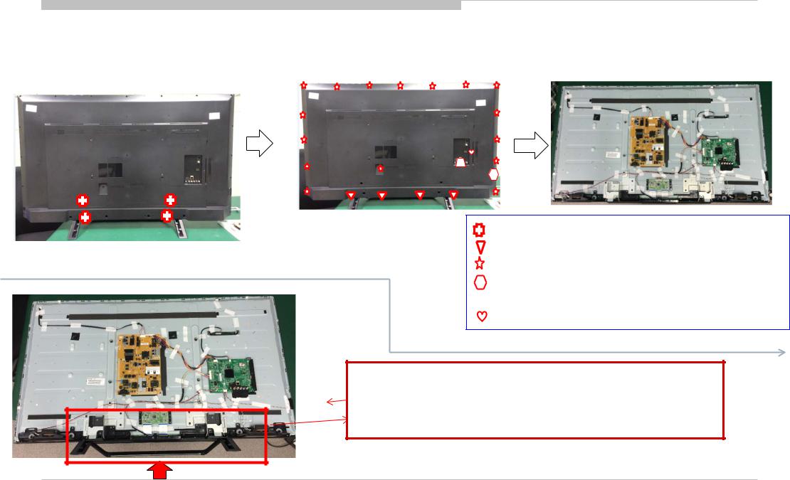
SERVICE POSITION
As for this model, the bottom of rear cover is installed between the stand assy and the panel.
Therefore according to the following procedure when performing adjustment and operation check after the part replacement.
<KDL-55W650D > |
2. Remove all screws on the Rear Cover to |
|
1. Remove all screws on the Stand |
||
Bezel & Main Board & Bracket (23 screws) |
||
to main unit (4 screws) |
||
|
3. After removing rear cover , lie down the main unit to a surface for following test/repair.
4-592-444-01 SCREW, +PSW M5X12
4-595-220-01 SCREW +BVTP Q4X12 TYPE2 N-S, ODM(T)
7-682-903-19 SCREW +PWH M3X6
4-595-222-01 SCREW +PWH M3X8 W7.5, ODM(T)
 4-595-219-01 SCREW +BVTP Q3X8 TYPE2 N-S, ODM(T) 4-595-213-01 SCREW +K M3X6, ODM(T)
Attention: This photo is based on Sony criteria for appearing standing the main unit after removing back cover and assembling the stand. But considering mechanical design of Taurus models and normal service process, it is not recommended to keep main unit standing by this status for repairing/testing at repair center. Please pay attention for avoiding possible scratch/deformation occurred.
Note: Remove rear cover, then assemble the stand to main unit. This will cause the stand with main unit fit closely, scratch or deformation may occurred easily on the stand or bezel deco.
9
KDL-55W650D UC2/LA1

SEC 1. DISASSEMBLY AND PARTS LIST
•Items with no part number and no description are not stocked because they are seldom required for roution service.
•The construction parts of an assembled part are indicated with a collation number in the remark colum.
•Items marked " * " are not stocked since they are seldom required for routine service. Some delay should be anticipated when ordering these items.
10
KDL-55W650D UC2/LA1
DISASSEMBLY AND PARTS LIST
1-1. KDL-55W650D
1-1-1. BASE STAND
REF. No. |
PART No. |
DESCRIPTION |
MARK |
|
|
1 |
A-2123-138-A |
STAND ASSY |
|
2 |
4-571-144-01 |
HANDLE |
|
|
3 |
4-592-438-01 |
STAND, NECK |
|
|
4-592-444-01 SCREW, +PSW M5X12
 4-595-223-01 SCREW +PSW M6X22, ODM(T)
1
1
2
3
If want to disassemble the stand neck from the stand ASSY, just remove the six screws.
11
KDL-55W650D UC2/LA1
DISASSEMBLY AND PARTS LIST
1-1. KDL-55W650D
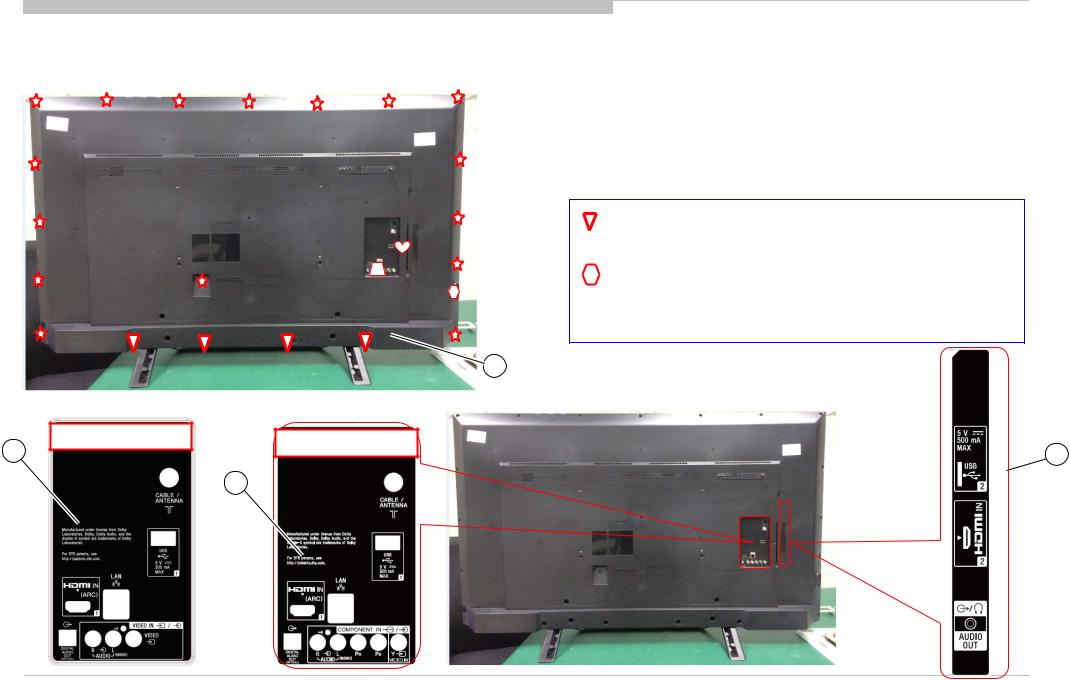
1-1-2. REAR COVER
REF. No. |
PART No. |
DESCRIPTION |
MARK |
|
|
4 |
4-592-418-21 |
COVER, REAR (55) |
|
5 |
4-593-164-01 |
LABEL, SIDE I/O |
for UC2 model |
|
6 |
4-596-363-01 |
LABEL, BACK I/O |
||
27 |
4-688-308-01 |
LABEL, BACK I/O |
for LA1 model |
|
 4-595-220-01 SCREW +BVTP Q4X12 TYPE2 N-S, ODM(T)
 7-682-903-19 SCREW +PWH M3X6
 4-595-222-01 SCREW +PWH M3X8 W7.5, ODM(T)
 4-595-219-01 SCREW +BVTP Q3X8 TYPE2 N-S, ODM(T)
  4-595-213-01 SCREW +K M3X6, ODM(T)
4
27 |
KDL-55W650D LA1 |
KDL-55W650D UC2 |
|
||
|
5 |
|
|
|
|
|
|
6 |
12
KDL-55W650D UC2/LA1

DISASSEMBLY AND PARTS LIST
1-1. KDL-55W650D
1-1-3. POWER BOARD, A BOARD AND SPEAKER
|
|
11 |
7 |
|
21 |
|
|
10 |
|
|
17 |
|
15 |
16 |
|
14 |
|
|
|
12
13
18 |
8 |
|
|
9 |
9 |
19 |
|
REF. No. |
PART No. |
DESCRIPTION |
MARK |
7 |
1-895-965-11 |
MOUNTED PWB POWER UNIT |
for UC2 model BOE panel |
|
1-897-087-11 |
MOUNTED PWB POWER UNIT LGD |
for UC2 model LGD panel |
8 |
1-895-964-21 |
MOUNTED PWB A |
for UC2 model |
|
1-897-053-11 |
MOUNTED PWB A |
for LA1 model |
9 |
1-895-956-11 |
MOUNTED PWB H |
|
10 |
1-910-111-41 |
CONNECTOR ASSY 16P (MB-PSU) |
|
11 |
1-910-111-44 |
CONNECTOR ASSY 6P (MB-WiFi) |
|
12 |
1-910-111-43 |
CONNECTOR ASSY (MB-IR-KEY) |
|
13 |
1-910-111-42 |
CONNECTOR ASSY 4P (MB-SP) |
|
14 |
1-910-111-45 |
LVDS CABLE (MB-Panel) |
|
15 |
4-592-437-01 |
SHEET, INSULATION |
|
16 |
4-593-163-01 |
BRACKET, SIDE I/O |
|
17 |
4-571-385-01 |
BRACKET, PSU |
|
18 |
1-859-187-11 |
LOUDSPEAKER (12W) |
|
19 |
1-910-111-46 |
FFC CABLE WITH TOP AL TAPE |
|
20 |
1-895-957-11 |
MOUNTED PWB KEY |
Assembly part |
21 |
1-895-960-11 |
WI-FI MODULE (WITH ANTENNA) |
|
22 |
4-592-421-01 |
HOLDER, WIFI |
|
|
|
20 |
|
|
|
|
21 |
 4-595-216-01 SCREW +PSW 3X6 W6.5, ODM(T) 4-595-221-01 TAPPING +PWH 3X8 TYPE2 N-S, ODM(T)
18
4-595-218-01 SCREW +PSW 4X8, ODM(T)
22
 2-580-592-01 SCREW, +PSW M3X8
  4-595-214-01 SCREW +PWH 3X5, ODM(T)
13
KDL-55W650D UC2/LA1
DISASSEMBLY AND PARTS LIST
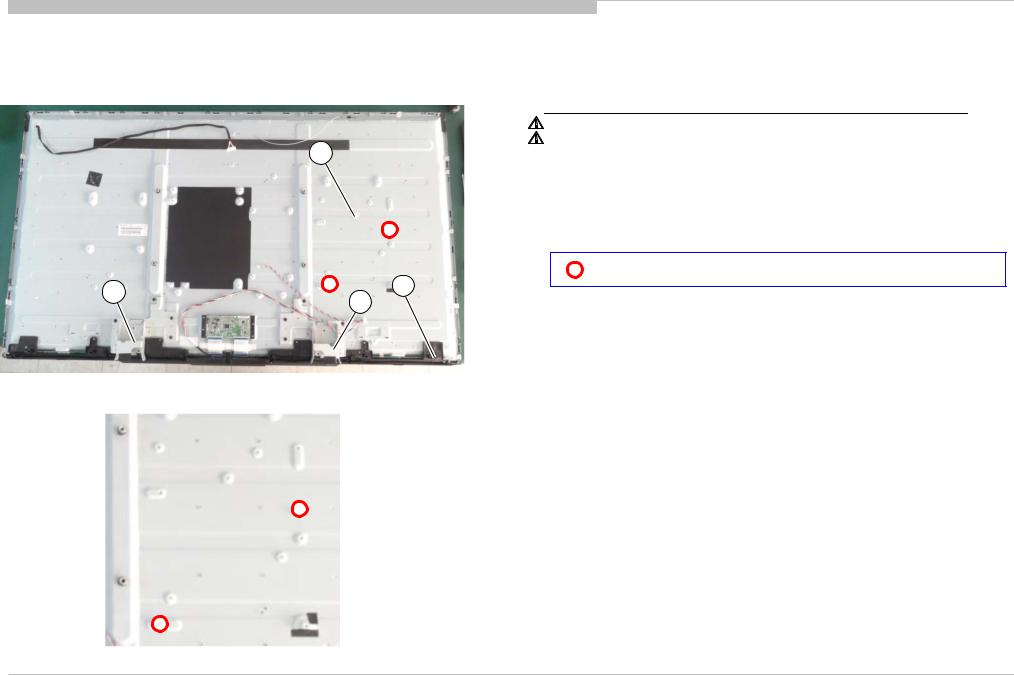
1-1. KDL-55W650D
1-1-4. LCD PANEL, DECO and COVER, BOTTOM
|
REF. No. |
PART No. |
DESCRIPTION |
MARK |
|
23 |
A-2123-136-A |
LCM ASSY (55) (BOE) |
|
|
|
A-2178-977-A |
LCM ASSY (55) (LGD) |
for UC2 model LGD panel |
23 |
24 |
4-592-433-01 |
BRACKET L, STAND |
|
|
25 |
4-592-434-01 |
BRACKET R, STAND |
|
|
26 |
4-592-419-01 |
COVER, BOTTM (55) |
|
|
4-542-283-01 |
BOLT, M3 |
25 |
26 |
|
24 |
|
|
|
|
14
KDL-55W650D UC2/LA1

DISASSEMBLY AND PARTS LIST
1-1. KDL-55W650D
1-1-5. MISCELLANEOUS
PART No. |
DESCRIPTION |
MARK |
1-492-980-21 |
REMOTE COMMANDER (RMT-TX102U) |
|
1-846-425-43 |
CORD SET, POWER-SUPPLY |
|
15
KDL-55W650D UC2/LA1

1-2. How to disassemble rear cover [KDL-55W650D]
PROCEDURE TO REMOVAL OF REAR COVER
1.Remove all screws on Rear Cover and AC Cover.
2.Open Rear Cover in order as below.
Hold the panel from the middle of bezel, and lift rear cover in the direction of the arrow.
16
KDL-55W650D UC2/LA1

1-3. Main Board Replacement Caution Guide[KDL-55W650D UC2/LA1]
1-3-1. Factory mode optional bit check and manual adjustment step [KDL-55W650D UC2/LA1]
1.Enter Factory Menu:
Press “home + 1999 + return” key to enter the factory menu. SW version can be saw in item 2, just like the below picture.
2.Check Region item (item 15)
Please check TV set s/n and set the Region item correctly
If TV s/n is 4,000,001-4,300,000 , please ensure the item set to “U.S”. Others s/n case, please ensure the item set to “MX”.
3.Exiting Factory Menu:
Press the remote control key “ ” to choose item 31, and then press remote control key “OK” to exit factory menu.
SW Version
Make sure the region option is in right setting after main board replacement.
Caution: This adjustment step for region is mandatory check item after main board replacement. Other items should be kept the original setting.
17
KDL-55W650D UC2/LA1
Loading...