


 Loading...
Operating Instructions
LCD Digital
Color TV
United States |
Canada |
1.800.222.SONY |
1.877.899.SONY |
KDL-52XBR10 |
Sony Customer Support |
|
|
U.S.A.: www.sony.com/tvsupport |
|
|
Canada: www.sony.ca/support |
|
KDL-46XBR10 |
Please Do Not Return |
|
the Product to the Store |
||
MBT-WZ5 |
||
|
||
© 2009 Sony Corporation |
|

Owner’s Record
The model, electric ratings, serial numbers and the date of manufacture are in the following locations:
Monitor: rear of the monitor at the bottom left Media receiver: on the underside and rear
Record these numbers in the spaces provided below. Refer to them whenever you call upon your Sony dealer regarding this unit.
Monitor
Model Name
Serial No.
Media receiver
Model Name
Serial No.
CAUTION
To prevent electric shock and blade exposure, do not use this polarized AC plug with an extension cord, receptacle or other outlet unless the blades can be fully inserted.
Operate the unit only on 120 V AC.
Avoid operating the unit at temperatures below 41°F (5°C).
Wireless Function of the Unit
The picture may be affected depending on the installation environment or setup of the monitor and media receiver (page 20).
It may take time to transmit pictures depending on the types of signal, fast motion, such as game pictures, etc.
If pictures from a PC or still images are displayed, flickering or blurring may occur.
This unit can be used only in combination of the supplied monitor and media receiver.
Do not operate this unit near medical equipment (pacemaker, etc.), as malfunction of the medical equipment may result.
Although this unit transmits/receives scrambled signals, be careful of unauthorised interception. We cannot be responsible for any trouble as a result.
Licensing Information
Macintosh is a trademark of Apple Inc., registered in the U.S. and other countries.
HDMI, the HDMI logo and High-Definition Multimedia Interface are trademarks or registered trademarks of HDMI Licensing, LLC.
Fergason Patent Properties, LLC:
U.S. Patent No. 5,717,422
U.S. Patent No. 6,816,141
Manufactured under license from Dolby Laboratories. Dolby and the double-D symbol are trademarks of Dolby Laboratories.
In the United States, TV Guide and other related marks are trademarks of Gemstar-TV Guide International, Inc. and/or its subsidiaries. In Canada, TV Guide is a registered mark of Transcontinental Inc., and is used under license by Gemstar-TV Guide International, Inc. and/or its subsidiaries.
The TV Guide On Screen system is manufactured under license from Gemstar-TV Guide International, Inc. and/or its subsidiaries.
The TV Guide On Screen system is protected by one or more of the following United States patents 6,498,895; 6,850,693; 6,396,546; 5,940,073; 6,239,794 to Gemstar-TV Guide International, Inc. and/ or its subsidiaries.
Gemstar-TV Guide International, Inc. and/or its related affiliates are not in any way liable for the accuracy or availability of the program schedule information or other data in the TV Guide On Screen system and cannot guarantee service availability in your area. In no event shall Gemstar-TV Guide International, Inc. and/or its related affiliates be liable for any damages in connection with the accuracy or availability of the program schedule information or other data in the TV Guide On Screen system.
Blu-ray Disc is a trademark.
“BRAVIA” and 

 , S-Force, Motionflow, BRAVIA Sync,
  and DMex are trademarks or registered marks of Sony Corporation.
“XrossMediaBar” is a trademark of Sony Corporation. “XMB” is a trademark of Sony Corporation and Sony Computer Entertainment Inc.
“PlayStation” is a registered trademark and “PS3” is a trademark of Sony Computer Entertainment Inc.
DLNA®, the DLNA Logo and DLNA CERTIFIED™ are trademarks, service marks, or certification marks of the Digital Living Network Alliance.
Your BRAVIA TV is ENERGY STAR® qualified in the “Home” mode.
It meets strict energy efficiency guidelines set by the U.S. Environmental Protection Agency and Department of Energy. ENERGY STAR is a joint program of these government agencies, designed to promote energy efficient products and practices.
Changes to certain features, settings, and functionalities of this TV (i.e. TV Guide, Picture/Sound, Light Sensor, Power Savings) can increase or change the power consumption.
Depending upon such changed settings, the power consumption may exceed the limits required for the ENERGY STAR qualification in the “Home” mode.
This manual is for the 46 and 52 inch BRAVIA KDL-XBR10 series models with screen size measured diagonally.
2
Contents
Introducing Your BRAVIA® TV
Experiencing Stunning HD with
Your BRAVIA TV . . . . . . . . . . . . . . . . . . . . .4 The Four Steps to a Full HD Experience . . . .4 TV Feature Highlights . . . . . . . . . . . . . . . . . . .5
Getting Started
Setting Up Your Monitor . . . . . . . . . . . . . . . . .6 Connecting the AC Power Cord . . . . . . . . . . .7 Using a Wall-Mount Bracket . . . . . . . . . . . . . .8 Locating Inputs and Outputs . . . . . . . . . . . . .10 Connecting the Unit . . . . . . . . . . . . . . . . . . .12 Connecting Internet & DLNA Certified™
Networks. . . . . . . . . . . . . . . . . . . . . . . . . . .15 Connecting Other Equipment . . . . . . . . . . . .16 Removing the Terminal Cover for
Monitor . . . . . . . . . . . . . . . . . . . . . . . . . . . .17 Installing the Unit Against a Wall or
Enclosed Area . . . . . . . . . . . . . . . . . . . . . .17 Securing the Monitor. . . . . . . . . . . . . . . . . . .18 Establishing the Wireless Communication
Between the Monitor and
Media Receiver. . . . . . . . . . . . . . . . . . . . . .20 Running Initial Setup. . . . . . . . . . . . . . . . . . .21
Operating the TV
Using the Remote Control. . . . . . . . . . . . . . .22
Remote Control Button Description . . . . . . .23
Unit Controls and Indicators . . . . . . . . . . . . .26 Programming the Remote Control . . . . . . . .27 Manufacturer’s Code List . . . . . . . . . . . . . . .28 Using Other Equipment with Your
Remote Control. . . . . . . . . . . . . . . . . . . . . .30 Remote Control Backlight . . . . . . . . . . . . . . .31
Exploring the XMB™ and TV Features
Category Icons . . . . . . . . . . . . . . . . . . . . . . .33 Accessing Photo, Music, and Video
Content . . . . . . . . . . . . . . . . . . . . . . . . . . . .34 BRAVIA Internet Video . . . . . . . . . . . . . . . . .35 Photo, Music, and Video . . . . . . . . . . . . . . . .36 BRAVIA Internet Widgets . . . . . . . . . . . . . . .39
Favorites . . . . . . . . . . . . . . . . . . . . . . . . . . . .41 TV Guide On Screen® . . . . . . . . . . . . . . . . .42
Background TV . . . . . . . . . . . . . . . . . . . . . . .44 Inputs . . . . . . . . . . . . . . . . . . . . . . . . . . . . . .44 Wide Mode . . . . . . . . . . . . . . . . . . . . . . . . . .45 BRAVIA® Sync™ with Control for HDMI. . . .47
Other Information
How to Care for Your BRAVIA . . . . . . . . . . .48 Troubleshooting . . . . . . . . . . . . . . . . . . . . . .48 Specifications . . . . . . . . . . . . . . . . . . . . . . . .50 Index . . . . . . . . . . . . . . . . . . . . . . . . . . . . . . .52
Welcome to the World of BRAVIA® HDTV
Thank you for purchasing this Sony BRAVIA® high-definition television. Use the documentation listed below to get the most out of your unit.
Safety Booklet
Provides precautionary measures to keep you and your unit safe. Read this information prior to setting up your unit.
Operating Instructions
Provides general unit operation information.
Quick Setup Guide
Provides unit setup information, illustrates sample optional equipment connection diagrams, and highlights TV features.
Reference Book
Offers the most complete unit operation information available for your unit and presents advanced customization details. Access it at www.sony.com/referencebook.
The unit operation information above has been designed in an eco-friendly manner to reduce the consumption of natural resources.
3
Introducing Your BRAVIA® TV
Experiencing Stunning HD with Your BRAVIA TV
To experience the stunning detail of your new BRAVIA TV, you need access to high-definition (HD) programming. Your BRAVIA TV can receive and display HD programming from:
•Over-the-air broadcasting via HD-quality antenna
•HD cable subscription
•HD satellite subscription
•Blu-ray Disc™ player or other HD compatible external equipment
Contact your cable, satellite or HD service provider for information on upgrading to HD programming.
The Four Steps to a Full HD Experience
Set, Source, Sound, and Setup
Along with your BRAVIA TV set, a complete HD system requires a source of HD programming, an HD sound system, and a proper connection setup. Refer to the Quick Setup Guide, enclosed separately, for connecting other optional equipment.
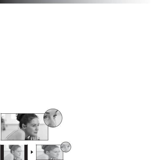
You can enjoy crisp, clear images, smooth movement, and high-impact visuals from 1080 HD signals as shown here.
When you compare a high-definition signal to a standard definition signal, you will notice a big difference in picture quality. If black bars appear as shown here, press WIDE on the remote control to fill the screen.
4
TV Feature Highlights
Your BRAVIA TV is equipped with the latest in TV technology.
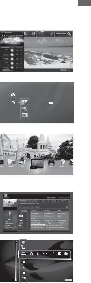
Broadband Internet Connectivity: BRAVIA Internet Video brings videos, movies and much more from the Internet to your unit (page 35). BRAVIA Internet Widgets allow you to access local weather, news, and much more. Displayed here is Widgets (page 39).
Digital Media Accessibility: Use the Photo, Music, and
Video Category icons to access photo, music, and video
files from DLNA CertifiedTM networked equipment or Sony |
Photo |
USB equipment. Displayed here is Photo USB (page 36). |
|
Central Location for Your Favorite Items: The
Favorites feature centralizes your favorite BRAVIA Internet Video and Widgets items, Photo, Music, Video content, TV channels, External Inputs, and Background TV themes for quick and easy access (page 41).
Channel Programming Information: TV Guide On Screen® provides TV programming information (page 42).
TV Home Menu: XMBTM (XrossMediaBar) unit menu provides you access to unit settings, photo, music, video, TV channel listings, and more (page 32).
DSC02991
Fri 5/25/2007 12:06 PM JPG
DSC00140.JPG
DSC00141.JPG
Product Support
Preferences
Settings
Picture & Display
Sound
Channels & Inputs
Network
 TV
TV
TV ®BRAVIA Your Introducing
5

Getting Started
Setting Up Your Monitor
This monitor is packaged with a detached Table-Top Stand so you can mount your monitor to a wall right away. If you are not mounting the monitor to a wall, you will need to attach the TableTop Stand. You will need a Phillips screwdriver and the supplied screws to complete the task. Look for the attachment instructions provided with the unit.
Be sure to consider the following while setting up your monitor:
•Disconnect all cables when carrying the monitor.
•Carry the monitor with the adequate number of people; larger size monitors require two or more people.
•Correct hand placement while carrying the monitor is very important for safety and to avoid damage.
•Ensure your monitor has adequate ventilation, see page 17.
•For best picture quality, do not expose the screen to direct illumination or sunlight.
•Avoid installing the monitor in a room with reflective wall and floor materials.
•Avoid moving the monitor from a cold area to a warm area. Sudden room temperature changes may cause moisture condensation. This may cause the monitor to show poor picture and/or poor color. Should this occur, allow moisture to evaporate completely before powering the monitor on.
•Read the supplied Safety Booklet for additional safety information.
•When cable connection is completed, be sure to secure the monitor to a stable surface or mount it to a wall. The designated Sony wall-mount bracket model and TV stand model name(s) are available under the “Other Information” section of Operating Instructions. For details on securing the monitor, see page 18.
6

Connecting the AC Power Cord
Make sure all connections are set before connecting the AC power cord.
Monitor
1Connect the supplied AC power cord to the monitor.
2Attach the stand cover.
Do not pinch the AC power cord.
Started Getting
3 Attach the terminal cover.
4
Media receiver
AC power cord (supplied)
7

Using a Wall-Mount Bracket
All models can be mounted to a wall using the Wall-Mount Bracket (not supplied) out of the box as packaged.
Prepare the monitor for the Wall-Mount Bracket before making cable connections.
Sony strongly recommends that you use the Wall-Mount Bracket model designed for your monitor (see page 49) and that wall-mounting of your monitor should be performed by a Sony dealer or licensed contractor.
•Follow the instruction guide provided with the Wall-Mount Bracket for your model. You may also need to refer to the online Reference Book for additional information for your unit model. Sufficient expertise is required in installing this monitor, especially to determine the strength of the wall for withstanding the monitor’s weight.
•Be sure to use the screws supplied with the Wall-Mount Bracket when attaching the mounting hooks to the monitor. (Do not use the screws that are intended for the Table-Top Stand attachment.)
The supplied M6 screws are designed so that they are 8 mm to 12 mm in length when measured from the attaching surface of the mounting hook.
Use of screws other than those supplied with the bracket may result in internal damage to the monitor or cause it to fall, etc.
When attaching to the Wall-Mount Bracket
8-12 mm
Spacer (black)
 Screw M6 × 16 (supplied with the Wall-Mount Bracket)
 Mounting Hook
Rear of the monitor
When attaching to the Floor Stand
8-12 mm
Spacer (silver)
 Screw M6 × 20 (supplied with the monitor)
 Mounting Hook
Rear of the monitor
•Be sure to store the unused screws and Table-Top Stand in a safe place until you are ready to attach the Table-Top Stand. Keep the screws away from small children. When you are using the Table-Top Stand, be sure to read page 19.
8
Locating Inputs and Outputs
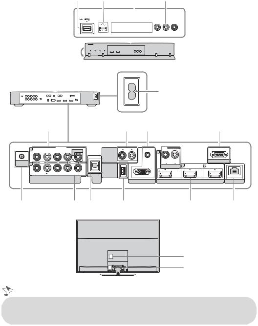
Front of media receiver
1 2 3 4
|
|
|
|
2 IN |
|
|
|
|
|
|
|
VIDEO |
2 IN |
|
|
|
||||||||||||
|
|
|
|
|
|
|
|
|
|
|
||||||||||||||||||
|
|
|
|
|
|
|
|
|
|
|
SERVICE |
ONLY |
|
|
|
VIDEO L (MONO) -AUDIO-R |
||||||||||||
|
|
|
|
|
|
|
|
|
|
|
|
|
|
|
|
|
|
|
|
|
|
|
|
|
|
|
|
|
|
|
|
|
|
|
|
|
|
|
|
|
|
|
|
|
|
|
|
|
|
|
|
|
|
|
|
|
|
|
|
|
|
|
|
|
|
|
|
|
|
|
|
|
|
|
|
|
|
|
|
|
|
|
|
|
|
|
|
|
|
|
|
|
|
|
|
|
|
|
|
|
|
|
|
|
|
|
|
|
|
|
|
|
|
|
|
|
|
|
|
|
|
|
|
|
|
|
|
|
|
|
|
|
|
|
|
|
|
|
|
|
|
|
|
|
|
|
|
|
|
|
|
|
|
|
|
|
|
|
|
|
|
|
|
|
|
|
|
|
|
|
|
|
|
|
|
|
|
|
|
|
|
|
|
|
|
|
|
|
|
|
|
|
|
|
|
|
|
|
|
|
|
|
|
|
|
|
|
|
|
|
|
|
|
|
|
|
|
|
|
|
|
|
|
|
|
|
|
|
|
|
|
|
|
|
|
|
|
|
|
|
|
|
|
|
|
|
|
|
|
|
|
|
|
|
|
|
|
|
|
|
|
|
|
|
|
|
|
|
|
|
|
|
|
|
|
|
|
|
|
|
|
|
|
|
|
|
|
|
|
|
|
|
|
|
|
|
|
|
|
|
|
|
|
|
|
|
|
|
|
|
|
|
|
|
|
|
|
|
Rear of media receiver |
|
|
|
5 |
|||
|
|
|
|
|
|
|
|
|
6 |
|
|
|
|
7 |
8 |
|
1 |
|
|
VIDEO IN |
|
R AUDIO L |
1 |
|
|
|
|
|
AUDIO OUT |
||
|
|
|
|
1 |
|
||
|
|
|
|
|
|
||
|
|
|
|
|
|
(VAR/FIX) |
AUDIO |
CABLE/ |
|
|
|
|
|
|
|
2 |
|
|
|
|
|
R AUDIO L |
|
ANTENNA |
|
|
|
|
|
||
|
|
|
|
|
AUDIO IN |
||
|
|
|
|
|
|
DMex/ |
|
|
|
|
|
|
(OPTICAL) |
|
|
|
R AUDIO L |
PR |
PB |
Y |
SERVICE |
|
|
|
DIGITAL |
|
RGB |
||||
|
COMPONENT IN |
|
|
||||
|
|
AUDIO |
|
||||
|
(1080p/1080i/720p/480p/480i) |
OUT |
|
PC IN |
|||
0 |
|
|
|
qa |
qs |
qd |
|
Rear of monitor |
|
|
|
|
|
|
|
3

 IN
IN
1
9
REMOTE
4
LAN
qf
3
5
•An HDMI or Component video (YPBPR) connection is required to view 480i, 480p, 720p, 1080i and 1080p video formats. The 1080/24p video format is available only with HDMI connection. This unit displays all video input signals in a resolution of 1,920 dots × 1,080 lines.
10
Item |
Description |
|
|
1HDMI IN 1/2/3/4 AUDIO IN R-AUDIO-L
HDMI (High-Definition Multimedia Interface) provides an uncompressed, alldigital audio/video interface between this unit and any HDMI-equipped audio/video equipment, such as a set-top box, DVD player, and A/V receiver. HDMI supports enhanced, or high-definition video, plus digital audio. Be sure to use only an HDMI cable that bears the HDMI logo.
Use the HDMI IN 1 port when connecting DVI equipment with a DVI-to-HDMI cable or adapter (not supplied). Equipment using a DVI connection also requires an additional audio connection using an audio cable connected to AUDIO (L/R).
2 |
USB |
Connects to USB equipment to access photo, music, and video files. |
|
|
|
3 |
SERVICE ONLY |
This port is for service only. |
|
|
|
4 |
VIDEO 2 IN |
Connects to the composite video and audio output ports on your A/V equipment. |
|
L (MONO)- |
If you have mono equipment, connect its audio output port to the media receiver’s |
|
AUDIO-R |
L (MONO) audio input port. |
|
|
|
5 |
AC IN |
Connects to your power source. Connect the supplied power cord to AC IN and the |
|
|
nearest wall outlet. |
6VIDEO IN 1/ This input port can be used as composite video input (VIDEO 1) or as component COMPONENT video input (COMPONENT 1). For composite use, connect the yellow jack to Y for
|
IN 1 (1080p/ |
video and use audio (L/R) for audio signals. For component connection, use Y, PB, |
|
1080i/720p/ |
PR for video signals and also connect the audio (L/R) for audio signals. |
|
480p/480i)/ |
By default, this unit will automatically detect and switch between VIDEO 1 and |
|
COMPONENT 1. To manually set the input type, press HOME, select Settings, |
|
|
R-AUDIO-L |
|
|
then Channels & Inputs, then select Video/Component 1 Selection. |
|
|
|
|
|
|
|
7 |
AUDIO OUT |
Connects to the left and right audio input jacks of your analog audio equipment. You |
|
(VAR/FIX) |
can use these outputs to listen to your unit’s audio through your stereo system. |
|
R-AUDIO-L |
|
|
|
|
8 |
PC IN |
Connects to a personal computer’s video and audio output connector. Can also be |
|
(RGB/AUDIO) |
connected to other analog RGB equipment. |
|
|
For some Apple Macintosh computers, it may be necessary to use an adapter (not |
|
|
supplied). If an adapter is used, connect the adapter to the computer before |
|
|
connecting the HD15-HD15 cable. |
|
|
You may need to adjust the unit settings or your PC’s resolution and timing (see |
|
|
page 14). |
|
|
|
9 |
REMOTE |
This jack is for receiving the external control signal. |
|
|
|
0 |
CABLE/ |
RF input that connects to your cable or over-the-air antenna. |
|
ANTENNA |
|
|
|
|
qa |
COMPONENT |
Component video provides better picture quality than the composite video. |
|
IN 2 |
Audio connection is required for the COMPONENT IN ports, connect audio (L/R). |
|
|
|
qs |
DIGITAL AUDIO |
Connects to the optical audio input of digital audio equipment that is PCM/Dolby* |
|
OUT (OPTICAL) |
Digital compatible. |
|
|
|
qd |
DMex/SERVICE |
This USB port is only for service unless you are connecting an optional BRAVIA |
|
|
Link module (DMex). |
qf |
LAN |
Connects to an existing network using an Ethernet cable. Be sure to complete |
|
|
Network Setup (page 21). |
*Manufactured under license from Dolby Laboratories. Dolby and the double-D symbol are trademarks of Dolby Laboratories.
Started Getting
11

Connecting the Unit
Cable System or VHF/UHF Antenna System
You can enjoy high-definition and standard-definition digital programming (if available in your area) along with standard-definition analog programming.
This unit is capable of receiving unscrambled digital programming for both cable (QAM and 8VSB) and external VHF/UHF antenna (ATSC).
Cable or VHF/UHF (or VHF only)
75-ohm coaxial cable 


 Rear of media receiver
CABLE/
ANTENNA
•It is strongly recommended that you connect the CABLE/ANTENNA input using a 75-ohm coaxial cable to receive optimum picture quality. A 300-ohm twin lead cable can easily be affected by radio frequency interference, resulting in signal degradation.
Cable System and VHF/UHF Antenna System
Use an optional A-B RF switch (not |
|
|
|
|
|
|
|
|
|
|
|
A-B RF Switch |
||||||||||
supplied) to switch between the cable |
Cable |
|
|
|
|
|
|
|
|
|
|
|
|
|
|
|
|
|
|
|
|
|
and over-the-air antenna programming, |
|
|
|
|
|
|
|
|
|
|
|
|
|
|
|
|
|
|
|
|
|
|
as shown here. |
Antenna |
|
|
|
|
|
|
|
|
|
|
|
|
|
|
|
|
|
|
|
|
|
Set the Cable/Antenna setting found |
|
|
|
|
|
|
|
|
|
|
|
|
|
|
|
|
|
|
|
|
|
|
under the Settings on the XMB™ to
Cable or Antenna for the type of input signal you choose.
HD Cable Box/HD Satellite Box
Rear of media


 receiver CABLE/
ANTENNA
You can enjoy high-definition programming by subscribing to a high-definition service or a highdefinition satellite service. For the best possible picture, make sure you connect this equipment to your media receiver via the HDMI or component video (with audio) input located on the rear of the media receiver.
Shown with HDMI Connection |
|
|
|
|
||||||
Rear of media receiver |
|
|
|
|
|
|
||||
|
1 |
|
VIDEO IN |
|
|
R AUDIO L |
|
|
|
|
|
|
|
|
AUDIO OUT |
1 |
|
|
|
||
|
|
|
1 |
|
|
|
|
|
||
|
|
|
|
|
|
(VAR/FIX) |
|
|
|
|
CABLE/ |
|
|
|
|
|
|
AUDIO |
|
|
REMOTE |
2 |
|
|
|
|
|
R AUDIO L |
|
|
||
ANTENNA |
|
|
|
|
|
3 |
|
4 |
||
|
|
|
|
|
|
DMex/ |
AUDIO IN |
|
|
|
|
R AUDIO L |
PR |
PB |
Y |
(OPTICAL) |
SERVICE |
|
|
|
|
|
DIGITAL |
|
|
|
|
|
||||
|
COMPONENT IN |
|
AUDIO |
|
RGB |
|
|
|
||
|
(1080p/1080i/720p/480p/480i) |
|
OUT |
|
PC IN |
|
IN |
LAN |
||
CATV/Satellite antenna cable
HD cable box/
HD satellite box
HDMI cable
12

Shown with DVI Connection
|
|
CATV/ |
|
|
Satellite |
AUDIO-L (white) |
Audio cable |
antenna |
cable |
Rear of media receiver |
|
AUDIO-R (red) |
|
|
|
|
||||
|
|
|
|
|
|
|||||
|
1 |
|
VIDEO IN |
|
R AUDIO L |
1 |
|
|
|
|
|
|
|
1 |
|
|
AUDIO OUT |
|
|
|
|
|
|
|
|
|
|
|
|
|
||
|
|
|
|
|
|
(VAR/FIX) |
|
|
|
|
CABLE/ |
|
|
|
|
|
AUDIO |
R AUDIO L |
|
|
REMOTE |
2 |
|
|
|
|
|
|
|
|||
ANTENNA |
|
|
|
|
|
3 |
|
4 |
||
|
|
|
|
|
|
DMex/ |
AUDIO IN |
|
|
|
|
|
|
|
|
(OPTICAL) |
|
|
|
|
|
|
R AUDIO L |
PR |
PB |
Y |
SERVICE |
|
|
|
|
|
|
DIGITAL |
|
|
|
|
|
||||
|
COMPONENT IN |
|
AUDIO |
RGB |
|
|
|
|
||
|
(1080p/1080i/720p/480p/480i) |
|
OUT |
PC IN |
|
|
IN |
LAN |
||
HD cable box/
HD satellite box
DVI-to-HDMI cable
Started Getting
•If your equipment has a DVI output and not an HDMI output, connect the DVI output to the HDMI IN 1 (with DVI-to-HDMI cable or adapter) and connect the audio output to the AUDIO IN (L/R) of HDMI IN 1.
Shown with Component Connection
Rear of media receiver
1 |
|
R AUDIO L |
|
VIDEO IN |
AUDIO OUT |
1 |
|
1 |
|||
|
(VAR/FIX)
CABLE/ |
|
|
|
|
|
AUDIO |
R AUDIO L |
|
ANTENNA |
2 |
|
|
|
|
|
3 |
|
|
|
|
|
|
AUDIO IN |
|||
|
|
|
|
|
|
DMex/ |
|
|
|
|
|
|
|
|
|
|
|
|
R AUDIO L |
PR |
PB |
Y |
(OPTICAL) |
SERVICE |
|
|
|
DIGITAL |
|
|
|
||||
|
COMPONENT IN |
|
AUDIO |
RGB |
|
|
||
|
(1080p/1080i/720p/480p/480i) |
|
OUT |
PC IN |
|
IN |
||
AUDIO-R (red) |
|
AUDIO-L (white) |
|
PR (red) |
Component video cable |
PB (blue) |
|
Y (green) |
|
CATV/Satellite antenna cable
HD cable box/
HD satellite box
REMOTE
4
LAN
Audio cable
(Continued) 13

Shown with PC connection
Use this unit as a monitor for your PC by connecting an HD15-HD15 cable connection as shown below.
This unit can also be connected to a PC with a DVI or HDMI output. (Refer to the supplied Quick Setup Guide.)
Rear of media receiver |
|
|
|
|
||||
|
1 |
|
VIDEO IN |
|
R AUDIO L |
1 |
|
|
|
|
|
1 |
|
|
AUDIO OUT |
|
|
|
|
|
|
|
|
|
||
|
|
|
|
|
|
(VAR/FIX) |
|
|
CABLE/ |
|
|
|
|
|
AUDIO |
R AUDIO L |
|
2 |
|
|
|
|
|
|
||
ANTENNA |
|
|
|
|
|
3 |
||
|
|
|
|
|
AUDIO IN |
|||
|
|
|
|
|
|
DMex/ |
|
|
|
|
|
|
|
|
|
|
|
|
R AUDIO L |
PR |
PB |
Y |
(OPTICAL) |
SERVICE |
|
|
|
DIGITAL |
|
|
|
||||
|
COMPONENT IN |
|
AUDIO |
RGB |
|
|
||
|
(1080p/1080i/720p/480p/480i) |
|
OUT |
PC IN |
|
IN |
||
REMOTE
4
LAN
HD15-HD15 cable (analog RGB)
Audio cable (stereo mini plugs)
PC Input Signal Reference Chart
After connecting the PC to the unit, set the output signal from your PC according to the supported resolutions and timings indicated below.
Supported resolutions |
|
|
Horizontal |
Vertical |
Standard |
||
Signal |
Horizontal |
× |
Vertical |
||||
frequency (kHz) |
frequency (Hz) |
|
|||||
|
(Pixel) |
|
(Line) |
|
|||
|
|
|
|
|
|||
VGA |
640 |
× |
480 |
31.5 |
60 |
VGA |
|
|
|
|
|
|
|
|
|
SVGA |
800 |
× |
600 |
37.9 |
60 |
VESA Guidelines |
|
|
|
|
|
|
|
|
|
XGA |
1,024 |
× |
768 |
48.4 |
60 |
VESA Guidelines |
|
|
|
|
|
|
|
|
|
WXGA |
1,280 |
× |
768 |
47.4 |
60 |
VESA |
|
|
|
|
|
|
|
|
|
|
1,280 |
× |
768 |
47.8 |
60 |
VESA |
|
|
|
|
|
|
|
|
|
|
1,360 |
× |
768 |
47.7 |
60 |
VESA |
|
|
|
|
|
|
|
|
|
SXGA |
1,280 |
× |
1,024 |
64.0 |
60 |
VESA |
|
|
|
|
|
|
|
|
|
HDTV* |
1,920 |
× |
1,080 |
67.5 |
60 |
CEA-861* |
|
|
|
|
|
|
|
|
|
~
•This unit’s PC input does not support Sync on Green or Composite Sync.
•This unit’s PC VGA input does not support interlaced signals.
•For the best picture quality, it is recommended to use the signals in the above chart. In plug and play, signals
with a 60 Hz vertical frequency will be detected automatically. (PC reboot may be necessary.)
*The 1080p timing when applied to the HDMI input will be treated as a video timing and not PC timing. This affects Picture settings and Wide Mode settings. To view PC content set Scene Select to Graphics,
Wide Mode to Full, and Display Area to Full Pixel.
•Connect the PC IN jack to the PC using an HD15-HD15 cable with ferrite core (analog RGB) and audio cable (see page 11).
•The unit enters the standby mode automatically when the PC is connected to the unit and no signal has been output from the PC for more than 30 seconds, see the online Reference Book for details.
14

Connecting Internet & DLNA Certified™ Networks
Connect an Ethernet cable from your home network to the LAN input of your unit to enjoy BRAVIA Internet features and/or connect to DLNA Certified™ media servers, see page 36 to learn more about these features.
Sample Network Connection Diagram
Internet Features
•BRAVIA Internet Video
•BRAVIA Internet Widgets
DLNA Certified™ Media Player or Sony USB Equipment Features
•Photo
•Music
•Video
Internet
Modem
Router
DLNA Certified™ Media Server
or
|
|
Wireless |
Renderer-compatible |
|
|
|
|||
|
|
Bridge |
Device |
|
|
|
|||
|
|
|
|
|
|
|
|
|
|
|
|
|
|
|
Started Getting
1 |
|
|
|
|
|
VIDEO IN |
|
|
R AUDIO L |
||
|
|
|
|
|
|
|
1 |
|
|
AUDIO OUT |
1 |
|
|
|
|
|
|
|
|
|
|
(VAR/FIX) |
|
CABLE/ |
|
|
|
|
|
|
|
|
|
AUDIO |
|
ANTENNA 2 |
|
|
|
|
|
|
|
|
R AUDIO L |
||
|
|
|
|
|
|
|
|
|
|
DMex/ |
AUDIO IN |
|
|
|
|
|
|
|
|
|
|
|
|
|
|
R AUDIO L |
PR |
PB |
Y |
(OPTICAL) |
SERVICE |
|
|||
|
|
DIGITAL |
|
|
|||||||
|
|
|
|
COMPONENT IN |
|
|
AUDIO |
|
RGB |
||
|
|
|
(1080p/1080i/720p/480p/480i) |
OUT |
|
PC IN |
|||||
3

 IN
IN
REMOTE
4
LAN
•For more information about compatible wireless bridges, visit https://internet.sony.tv
•Refer to your DLNA Certified equipment’s operating instructions for setup and connection information.
15
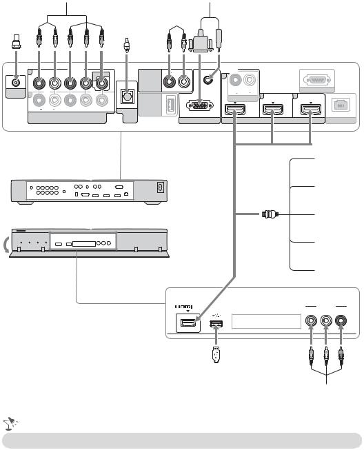
Connecting Other Equipment
CABLE/ |
|
|
|
|
|
|
|
|
Digital audio |
Analog audio |
|
|
|
|
|
||||||||||
|
|
Digital |
|
|
equipment |
equipment |
Personal |
||||||||||||||||||
ANTENNA |
|
|
recorder |
|
(A/V Receiver/Home Theater) |
computer |
|||||||||||||||||||
|
|
|
|
|
|
|
|
|
|
|
|
|
|
|
|
|
|
|
|
|
|
|
|
|
|
|
|
|
|
|
|
|
|
|
|
|
|
|
|
|
|
|
|
|
|
|
|
|
|
|
|
|
|
|
|
|
|
|
|
|
|
|
|
|
|
|
|
|
|
|
|
|
|
|
|
|
|
|
|
|
|
|
|
|
|
|
|
|
|
|
|
|
|
|
|
|
|
|
|
|
|
|
|
|
|
|
|
|
|
|
|
|
|
|
|
|
|
|
|
|
|
|
|
|
|
|
|
|
|
|
|
|
|
|
|
|
|
|
|
|
|
|
|
|
|
|
|
|
|
|
|
|
|
|
|
1 |
|
VIDEO IN |
|
|
R AUDIO L |
|
|
|
|
AUDIO OUT |
1 |
||
|
|
1 |
|
|
||
|
|
|
|
|
||
|
|
|
|
|
(VAR/FIX) |
AUDIO |
CABLE/ |
|
|
|
|
|
|
|
|
|
|
|
R AUDIO L |
|
ANTENNA 2 |
|
|
|
|
|
|
|
|
|
|
|
AUDIO IN |
|
|
|
|
|
|
DMex/ |
|
|
|
|
|
(OPTICAL) |
|
|
R AUDIO L |
PR |
PB |
Y |
SERVICE |
|
|
DIGITAL |
|
|
||||
COMPONENT IN |
|
|
RGB |
|||
|
AUDIO |
|
||||
(1080p/1080i/720p/480p/480i) |
|
OUT |
|
PC IN |
||
3

 IN
IN
REMOTE
4
LAN
|
Blu-ray |
|
|
Disc Player/ |
|
Rear of media receiver |
“PS3” |
|
DVD |
||
|
||
|
player |
|
|
Digital |
|
|
satellite |
|
Front of media receiver |
receiver |
|
|
Digital |
|
|
cable box |
|
|
Audio |
|
|
system |
|
2 IN |
VIDEO 2 IN |
|
SERVICE ONLY |
VIDEO L (MONO) -AUDIO-R |
|
|
|
|
|
|
|
|
|
|
|
|
|
|
|
|
|
|
|
|
|
|
|
|
|
|
|
|
|
|
|
|
|
|
|
|
|
|
|
|
|
|
|
|
|
|
|
|
VCR/ |
||||||
|
|
|
|
|||||||
USB |
||||||||||
|
|
|
|
Game system/ |
||||||
|
|
|
|
Camcorder |
||||||
• Refer to the Quick Setup Guide (supplied) when connecting other equipment to your unit.
16
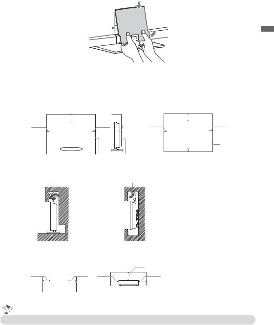
Removing the Terminal Cover for Monitor
2 
1 


Installing the Unit Against a Wall or Enclosed Area
Make sure that your unit has adequate ventilation. Allow enough space around the unit as shown below. Avoid operating the unit at temperatures below 41 °F (5 °C).
Monitor
Installed with stand |
Installed on the wall |
|
|
|
11 7/8 inches |
|
|
|
|
11 7/8 inches |
||||||
|
|
|
(30 cm) |
3/8 inches |
|
|
|
(30 cm) |
||||||
4 inches |
|
|
|
|
4 inches |
2 |
4 inches |
|
|
|
|
|||
|
|
|
|
|
|
|
(6 cm) |
|
|
|
|
|||
(10 cm) |
|
|
|
|
(10 cm) |
|
|
|
(10 cm) |
|
|
|
|
|
|
|
|
|
|
|
|
|
|
|
|
|
|||
|
|
|
|
|
|
|
|
|
|
|
|
|
|
|
|
|
|
|
|
|
|
|
|
|
|
|
|
|
|
4 inches (10 cm)
4 inches
(10 cm)
Leave at least this much space around the set.
Leave at least this much space around the set.
Never install the monitor as follows:
Air circulation is blocked. |
Air circulation is blocked. |
Started Getting
Wall
Wall
Media receiver
Top |
|
|
|
|
|
Front |
|
|
|
|
|
|
|
|
|
|
|
|
|
|
|
|
|
|
2 inches |
||||
2 inches |
|
2 inches |
|
|
|
(5 cm) |
||||||||
|
2 inches |
|
|
|
|
|
2 inches |
|||||||
(5 cm) |
|
(5 cm) |
(5 cm) |
|
|
|
|
|
(5 cm) |
|||||
|
|
|
|
|
|
|||||||||
|
|
|
|
|
|
|
|
|
|
|
|
|
|
|
|
|
|
|
|
|
|
|
|
|
|
|
|
|
|
|
|
|
|
|
|
|
|
|
|
|
|
|
|
|
Leave at least this much space around the set.
• Inadequate ventilation can lead to overheating of the unit and may cause unit damage or cause a fire.
17
Loading...