


 Loading...
Sony KDL-52V4100, KDL-52W4100, KDL-46W4150, KDL-40W4100, KDL-46W4100 User Manual
...3-297-694-13(1)
LCD Digital Color TV
Operating Instructions
KDL-32XBR6 KDL-40V4100 KDL-40W4100
KDL-37XBR6 KDL-42V4100 KDL-46W4100
KDL-40V4150 KDL-46V4100 KDL-52W4100
KDL-52V4100 KDL-46W4150
© 2008 Sony Corporation

Owner’s Record
The model and serial numbers are located at the rear of the TV. Record these numbers in the spaces provided below. Refer to them whenever you call upon your Sony dealer regarding this TV.
Model Name
Serial No.
CAUTION
To prevent electric shock and blade exposure, do not use this polarized AC plug with an extension cord, receptacle or other outlet unless the blades can be fully inserted.
s Operate the TV only on 120 V AC.
Declaration of Conformity
Trade Name: SONY
Model: KDL-32XBR6/KDL-37XBR6/
KDL-40V4150/KDL-40V4100/
KDL-42V4100/KDL-46V4100/
KDL-52V4100/KDL-40W4100/
KDL-46W4100/KDL-52W4100/
KDL-46W4150
Responsible Party: Sony Electronics Inc.
Address: 16530 Via Esprillo,
San Diego, CA 92127 U.S.A.
Telephone Number: 858-942-2230
This device complies with part 15 of the FCC rules. Operation is subject to the following two conditions: (1) This device may not cause harmful interference, and (2) this device must accept any interference received, including interference that may cause undesired operation.
NOTIFICATION
This equipment has been tested and found to comply with the limits for a Class B digital device, pursuant to Part 15 of the FCC Rules. These limits are designed to provide reasonable protection against harmful interference in a residential installation. This equipment generates, uses and can radiate radio frequency energy and, if not installed and used in accordance with the instructions, may cause harmful interference to radio communications.
However, there is no guarantee that interference will not occur in a particular installation. If this equipment does cause harmful interference to radio or television reception, which can be determined by turning the equipment off and on, the user is encouraged to try to correct the interference by one or more of the following measures:
sReorient or relocate the receiving antenna.
sIncrease the separation between the equipment and receiver.
sConnect the equipment into an outlet on a circuit different from that to which the receiver is connected.
sConsult the dealer or an experienced radio/ TV technician for help.
Pursuant to FCC regulations, you are cautioned that any changes or modifications not expressly approved in this manual could void your authority to operate this equipment.
For Customers in Canada
This Class B digital apparatus complies with Canadian ICES-003.
Note
This television includes a QAM demodulator which should allow you to receive unscrambled digital cable television programming via subscription service to a cable service provider. Availability of digital cable television programming in your area depends on the type of programming and signal provided by your cable service provider.
Licensing Information
Macintosh is a trademark of Apple Inc., registered in the U.S. and other countries.
HDMI, the HDMI logo and High-Definition Multimedia Interface are trademarks or registered trademarks of HDMI Licensing, LLC.
Fergason Patent Properties, LLC:
U.S. Patent No. 5,717,422
U.S. Patent No. 6,816,141
Manufactured under license from Dolby Laboratories. “Dolby” and double-D symbol are trademarks of Dolby Laboratories.
In the United States, TV Guide and other related marks are registered marks of Gemstar-TV Guide International, Inc. and/or one of its affiliates. In Canada, TV Guide is a registered mark of Transcontinental Inc., and is used under license by Gemstar-TV Guide International, Inc.
The TV Guide On Screen system is manufactured under license from Gemstar-TV Guide International, Inc. and/or one of its affiliates.
The TV Guide On Screen system is protected by one or more of the following United States patents 4,908,713; 6,498,895; 6,850,693; 6,396,546; 5,940,073; 6,239,794 to Gemstar-TV Guide International, Inc. and/or its subsidiaries.
Gemstar-TV Guide International Inc. and/or its related affiliates are not in any way liable for the accuracy or availability of the program schedule information or other data in the TV Guide On Screen system and cannot guarantee service availability in your area. In no event shall Gemstar-TV Guide International, Inc. and/or its related affiliates be liable for any damages in connection with the accuracy or availability of the program schedule information or other data in the TV Guide On Screen system.
Blu-ray Disc is a trademark.
“BRAVIA” and 


 , S-Force, Motionflow, BRAVIA Sync,
  , DMex and “x.v. Color” are trademarks or registered marks of Sony Corporation.
“XrossMediaBar” is a trademark of Sony Corporation. “XMB” is a trademark of Sony Corporation and Sony Computer Entertainment Inc.
“PLAYSTATION” is a registered trademark and “PS3” is a trademark of Sony Computer Entertainment Inc.
Adobe is a registered trademark or a trademark of Adobe Systems Incorporated in United States and/or other countries.
For Customers in the United States
Lamp in this product contains mercury. Disposal of these materials may be regulated due to environmental considerations. For disposal or recycling information, please contact your local authorities or the Electronic Industries Alliance (www.eiae.org).
CAUTION
Use the following Sony TVs only with the following WALL-MOUNT BRACKET or TV-stand.
|
|
|
Sony TV Model No. |
|
|||
|
KDL-32XBR6 |
KDL-37XBR6 |
KDL-40V4150 |
KDL-42V4100 |
KDL-46V4100 |
KDL-52V4100 |
|
|
KDL-40V4100 |
KDL-46W4100 |
KDL-52W4100 |
||||
|
|
|
KDL-40W4100 |
|
|
KDL-46W4150 |
|
|
|
|
|
|
|
|
|
Sony |
|
|
|
|
|
|
|
Wall-Mount |
|
|
SU-WL500 |
|
|
|
|
Bracket |
|
|
|
|
|
||
|
|
|
|
|
|
|
|
Model No. |
|
|
|
|
|
|
|
Sony TV |
— |
|
|
WS-S10LS |
|
||
|
|
|
|
|
|
|
|
Stand |
|
|
SU-FL300M |
|
|
— |
|
Model No. |
|
|
|
|
|
|
|
|
— |
|
SU-FL300L |
||||
|
|
|
|||||
|
|
|
|
|
|
|
|
Install TV Stands SU-FL300L and SU-FL300M using the red-printed paper template supplied with those stands.
Use with other WALL-MOUNT BRACKET or TV-stand may cause instability and possibly result in injury.
To Customers
Sufficient expertise is required for installing the specified TV. Be sure to subcontract the installation to a Sony dealer or licensed contractor and pay adequate attention to safety during the installation.
2
Contents
Welcome to the World of BRAVIA®
The Four Steps to a Full HD Experience: |
|
Set, Sound, Source, and Setup .................... |
4 |
Picture Quality and Aspect Ratio....................... |
4 |
TV Home Menu: XMB™ (XrossMediaBar).......... |
5 |
Getting Started |
|
1. Installing the TV............................................... |
6 |
Carrying the TV .............................................. |
6 |
Preparation for Table-Top Stand .................... |
6 |
Preparation for Wall-Mount Bracket ............... |
7 |
When Installing the TV Against a Wall or |
|
Enclosed Area............................................. |
8 |
Bundling the Connecting Cables .................... |
8 |
Securing the TV.............................................. |
9 |
2. Locating Inputs and Outputs ....................... |
10 |
3. Connecting the TV......................................... |
12 |
Cable System or VHF/UHF Antenna |
|
System ...................................................... |
12 |
Cable System and VHF/UHF Antenna |
|
System ...................................................... |
12 |
HD Cable Box/HD Satellite Box.................... |
12 |
PC................................................................. |
14 |
Other Equipment .......................................... |
15 |
4. Setting Up the Channel List |
|
– Initial Setup ............................................... |
16 |
Operating the TV |
|
Inserting Batteries into the Remote |
|
Control.......................................................... |
18 |
When Using the Remote Control ..................... |
18 |
TV Controls........................................................ |
18 |
Remote Control Button Description ................ |
19 |
Indicators ........................................................... |
23 |
Exploring Fun Features |
|
Favorites ............................................................ |
24 |
Displaying Favorites ..................................... |
24 |
Navigating Favorites..................................... |
24 |
Adding to Favorites ...................................... |
24 |
Removing from Favorites ............................. |
24 |
Background TV.................................................. |
25 |
Navigating Background TV........................... |
25 |
Using BRAVIA Sync with Control for |
|
HDMI ............................................................. |
25 |
How to Use TV Guide On Screen..................... |
26 |
Using P&P and PIP Features............................ |
28 |
To Enter P&P and PIP.................................. |
28 |
To Change Inputs or Channels .................... |
28 |
To Exit from P&P and PIP ............................ |
28 |
Using TV Settings |
|
Media Category Icons ....................................... |
29 |
Adjusting TV Settings ............................. |
29 |
Watching TV ........................................... |
29 |
Accessing External Inputs ...................... |
29 |
Navigating through TV Home Menu on |
|
XMB™............................................................ |
30 |
TV Settings Descriptions.................................. |
31 |
Product Support...................................... |
31 |
Clock/Timers Settings............................. |
31 |
Picture Settings ...................................... |
32 |
Sound Settings ....................................... |
34 |
Screen Settings ...................................... |
35 |
Channel Settings .................................... |
37 |
CC Closed Captions (CC) Settings............... |
38 |
Parental Lock Settings............................ |
38 |
External Inputs Settings.......................... |
41 |
HDMI Settings ........................................ |
41 |
General Setup Settings .......................... |
42 |
Initial Setup............................................. |
42 |
Other Information |
|
Troubleshooting................................................ |
43 |
Specifications.................................................... |
46 |
Index................................................................... |
47 |
Quick Setup Guide (separate volume) |
Customer Support |
Provides a variety of optional equipment |
http://www.sony.com/tvsupport |
connection diagrams. |
On-line Registration |
|
United States |
|
http://productregistration.sony.com |
|
Canada |
|
http://www.sonystyle.ca/registration |
3
Welcome to the World of BRAVIA®
Thank you for purchasing this Sony BRAVIA® high-definition television. The quality of the image you see on your BRAVIA TV is only as good as the quality of the signal it receives. To experience the stunning detail of your new BRAVIA TV, you need access to HD programming. Your BRAVIA TV can receive and display HD programming from:
•Over-the-air broadcasting via HD-quality antenna
•HD cable subscription
•HD satellite subscription
•Blu-ray Disc™ player or other HD compatible external equipment
Contact your cable or satellite provider for information on upgrading to HD programming.
To learn more about HDTV, visit:
U.S.A. http://www.sony.com/HDTV
Canada http://www.sonystyle.ca/hd
The Four Steps to a Full HD Experience: Set, Sound, Source, and Setup
Along with your BRAVIA TV set, a complete HD system requires an HD sound system, a source of HD programming and proper setup connections. This manual explains basic setup connections (see page 12). The Quick Setup Guide, enclosed separately, illustrates how to connect other optional equipment.
Picture Quality and Aspect Ratio
You can enjoy crisp, clear images, smooth movement and high-impact visuals from 1080 HD signals. When you compare a high-definition signal to a standard analog signal, you will notice a big difference.
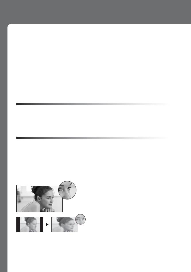
High-definition and standard-definition signals are transmitted with different aspect ratios (the width-to-height ratio of the image). HDTV uses a wider screen than conventional standarddefinition TV.
16:9 (high-definition) source
Most HDTV signals use a wide screen aspect ratio of 16:9. The 16:9 fills your BRAVIA screen, maintaining a crisp, clear, vivid picture.
4:3 (standard-definition) source
Most standard-definition signals use a boxy 4:3 aspect ratio. When a 4:3 image is displayed on an HDTV, you will see black bars on the sides. The picture quality may not be as sharp as with HD sources.
~
•You can use the Wide Mode function of the TV to adjust the 4:3 image to fit the entire screen (see pages 22, 35 and 36).
4
TV Home Menu: XMB™ (XrossMediaBar)
The XMB™ is an easy way to access the TV settings for customizing, making adjustments, viewing the available TV channels and selecting the connected equipment. Press the HOME button on your remote control to display the XMB™.
Product Support
Clock/Timers
Settings
Sound
Screen
Channel
TV
Media
Category
Bar
Category Object Bar
From the horizontal Media Category Bar you can control:
•Settings: timer, picture, sound, screen and other options (see page 31 for customization options).
•TV Channels: TV Guide On Screen™ and available channels are displayed on the vertical Category Object Bar.
•External Inputs: cable, satellite, VCR, DVD players or other optional equipment can also be selected from the Category Object Bar from the External Inputs.
~
•This manual is for the 32 class, 37, 40, 42, 46 and 52 inch BRAVIA KDL-XBR6, V and W series models with screen size measured diagonally. The 32 class has a 31.5 inch viewable image size (measured diagonally).
5
Getting Started
1. Installing the TV
This TV can be mounted on a wall using a WallMount Bracket or placed on a TV stand (each sold separately). This section will explain:
•How to carry the TV
•Preparation for a Table-Top stand
•Preparation for a Wall-Mount Bracket
•Installation against a wall or enclosed area
•Bundling the connecting cables
•Securing the TV
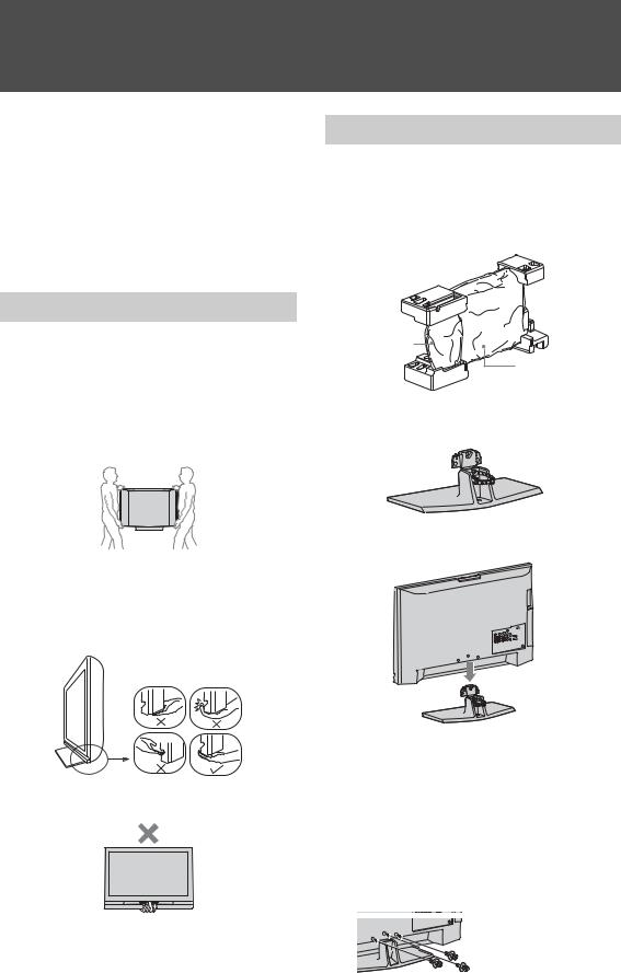
Carrying the TV
Be sure to follow these guidelines to protect your property and avoid causing serious injury.
•Before carrying the TV, disconnect all cables.
•Carrying the large size TV requires two or more people.
•When carrying the TV, place your hand as illustrated and hold it securely. Do not subject the TV to shocks, vibration, or excessive force.
•Lift the TV by placing your palm directly underneath the panel but do not:
•squeeze the speaker grill area
•place your fingers in the groove above the speaker grill area
•put stress on the LCD panel.
Preparation for Table-Top Stand
Follow the assembling steps required to place on a TV stand (except models: KDL-52V4100 and KDL-52W4100).
1Remove the Table-Top Stand and screws from the carton. The screws can be found in the accessory bag.
Table-Top
Stand
TV Unit
2Place the Table-Top Stand on a level and stable surface.
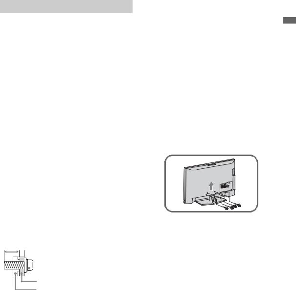
3Gently slide the TV unit onto the neck of the Table-Top Stand and align the screw holes.
• Do not lift the TV from the bottom center.
6
~
•Do not put stress on the LCD panel or the frame around the screen.
•Be careful to not pinch your hands or the AC power cord when you install the TV unit to the Table-Top Stand.
4Use the supplied screws to attach the TV unit to the Table-Top Stand. Shown here with a three screw model; other models may require screwing four screws (refer to the “Attaching the Table-Top Stand” flyer).
If an electric screwdriver is used, set the torque to tighten at approximately 1.5 N·m, 15 Kgf·cm.
Preparation for Wall-Mount Bracket
All models are ready to be mounted on a wall. Models KDL-52V4100 and KDL-52W4100 will require detaching the Table-Top stand.
•For product protection and safety reasons, Sony strongly recommends that you use the Wall-Mount Bracket model designed for your TV and the wall-mounting of your TV should be performed by a Sony dealer or licensed contractor.
•For bracket installation, refer to the supplied “Installing the Wall-Mount Bracket” and the instruction guide provided by the Wall-Mount Bracket model for your TV. Sufficient expertise is required in installing this TV, especially to determine the strength of the wall for withstanding the TV’s weight.
•Be sure to use the screws supplied with the Wall-Mount Bracket when attaching the mounting hooks to the TV set.
The supplied screws are designed so that they are 8 mm to 12 mm in length when measured from the attaching surface of the mounting hook.
The diameter and length of the screws differ depending on the Wall-Mount Bracket model. Use of screws other than those supplied may result in internal damage to the TV set or cause it to fall, etc.
8-12 mm
Screw (supplied with the Wall-Mount
 Bracket)
Mounting Hook
Rear of the TV set
•Do not remove the Table-Top Stand of the KDL-52V4100 and KDL-52W4100 for any reason other than to wall-mount the TV.
•Models KDL-32/37XBR6, KDL-40V4150, KDL-40/42/46V4100, KDL-40/46W4100 and KDL-46W4150 can be wall-mounted as packaged. If you decided to use the TV with the TV stand and later want to wall-mount the TV, follow the steps provided on this page to remove the Table-Top Stand.
•Be sure to store the unused screws and Table-Top Stand in a safe place until you are ready to attach the Table-Top Stand. Keep the screws away from small children.
Follow the simple steps below to remove the Table-Top Stand:
1Unplug the AC power cord and disconnect all the cables from the TV.
2Secure the Mounting Hook to the rear of the TV.
3Adjust the angle of the Mounting Hook.
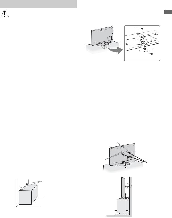
4Remove the screws on the rear of the TV (see illustration in the next column). Do not remove any other screws from the TV.
5When screws are removed, lift the TV off the stand. Make sure that you carry out this task with at least two or three people. Do not attempt to lift the TV by yourself.
•Shown here is model KDL-52V4100; other models may only require removal of three screws (refer to the “Attaching the Table-Top Stand” flyer).
(Continued)
Started Getting
7

When Installing the TV Against a Wall or Enclosed Area
Make sure that your TV has adequate air circulation. Allow enough space around the TV as shown below. Avoid operating the TV at temperatures below 41 °F (5 °C).
Installed with stand
|
|
|
|
|
11 7/8 inches |
|
|||||||||||
|
|
|
|
|
(30 cm) |
3/8 inches |
|||||||||||
4 inches |
|
|
|
|
|
4 inches |
|
2 |
|||||||||
|
|
|
|
|
|||||||||||||
|
|
|
|
|
|
|
|
(6 cm) |
|||||||||
(10 cm) |
|
|
|
|
|
(10 cm) |
|
|
|
|
|
|
|||||
|
|
|
|
|
|
|
|
|
|||||||||
|
|
|
|
|
|
|
|
|
|
|
|
|
|
|
|
|
|
|
|
|
|
|
|
|
|
|
|
|
|
|
|
|
|
|
|
|
|
|
|
|
|
|
|
|
|
|
|
|
|
|
|
|
|
|
|
|
|
|
|
|
|
|
|
|
|
|
|
|
|
|
|
Leave at least this much space around the set.
Installed on the wall
11 7/8 inches
(30 cm)
4 inches
(10 cm)
4 inches (10 cm)
4 inches
(10 cm)
Leave at least this much space around the set.
Never install the TV set as follows:
Air circulation is blocked. |
Air circulation is blocked. |
Wall
Wall
~ |
•Inadequate air circulation can lead to overheating of the TV and may cause damage to your TV or cause a fire.
Consider the following for best picture quality
•Do not expose the screen to direct illumination or sunlight.
•Use spot lighting directed down from the ceiling or cover the windows that face the screen with opaque drapery.
•Install the TV in a room where the floor and walls are not of a reflective material.
•When moving the TV from a cold area to a warm area, a sudden room temperature change may cause the TV’s picture to blur or show poor color due to moisture condensation. Should this occur, please wait a few hours to allow the moisture to evaporate before powering on the TV.
Bundling the Connecting Cables
You can bundle the connecting cables as illustrated below.
~
• Do not bundle the AC power cord with other connecting cables.
8
Securing the TV
Sony strongly recommends taking measures to prevent the TV from toppling over. Unsecured TVs may topple and result in property damage, serious bodily injury or even death.
Prevent the TV from Toppling Over
sSecure the TV to a wall and/or stand.
sDo not allow children to play or climb on furniture and TV sets.
sAvoid placing or hanging items on the TV.
sNever install the TV on:
•slippery, unstable and/or uneven surfaces.
•furniture that can easily be used as steps, such as a chest of drawers.
sInstall the TV where it cannot be pulled, pushed, or knocked over.
sRoute all AC power cords and connecting cables so that they are not accessible to curious children.
Use a Sony TV Stand
Use a Sony specified TV stand (see page 2) and follow the instruction manual provided with the Sony TV stand.
If a Sony specified TV stand is not used, consider the following recommended measures.
Recommended Measures to Secure the TV
Secure the Stand for the TV
Make sure the TV stand can adequately support the weight of the TV. Use two angle braces (not supplied) to secure the stand.
For each angle brace use the appropriate hardware to:
•attach one side of the angle brace to the wall stud.
•attach the other side to the TV stand.
Angle brace
Stand
Secure the TV to the Stand
Use the optional hardware listed below (not supplied):
•M6 × 12-18 mm anchor bolt (screwed into the TV’s Table-Top Stand)
•A screw or similar (attach it to the TV stand)
•Rope or chain (strong enough to support the weight of the TV). Make sure that there is no excess slack in the rope or chain.
An alternative way to secure the TV is with an |
Getting |
|
optional Sony Support Belt Kit. |
||
|
||
Anchor |
Started |
|
bolt |
||
|
||
Screw |
|
|
Screw hole on the |
|
|
Table-Top Stand |
|
~
Contact Sony Customer Support to obtain the optional Support Belt Kit by providing your TV model name.
•For United States call: 1-800-488-7669 or visit: www.sony.com/accessories
•For Canada call: 1-877-899-7669
Anchor the TV to the Wall
Use the hardware listed below (not supplied):
•Two M6 × 12-18 mm anchor bolts (screw into the top-most wall-mount holes located on the rear of the TV)
•Rope or chain (attach to one M6 anchor bolt)
•Wall-anchor (attach to the wall stud) strong enough to support the weight of the TV (pass the rope through the wall-anchor, then attach to the other M6 anchor bolt)
Anchor bolts
Wall-mount |
Rope or |
|
chain |
||
holes |
||
|

 Wall-
Wall-
anchor
~
•Securing the TV to the stand without securing it and the stand to the wall provides minimum protection against the TV toppling over. For further protection, follow all three measures recommended above.
9

2. Locating Inputs and Outputs
Rear of TV
|
VIDEO IN |
COMPONENT IN |
PC IN |
|
1 |
3 |
1 |
2 |
|
1 |
|
Y |
|
|
|
|
|
RGB |
|
|
S VIDEO |
PB |
|
|
|
|
|
|
|
|
VIDEO |
PR |
|
|
|
L |
L |
|
|
|
(MONO) |
|
|
|
|
AUDIO |
AUDIO |
|
AUDIO |
|
R |
R |
|
|
(1080p/1080i/720p/480p/480i)
R
AUDIO
IN |
DIGITAL |
1 |
OUT |
(OPTICAL) |
3
4 AUDIO OUT
L
L |
AUDIO |
|
R
(VAR/FIX)
5
DMex/
SERVICE
6
7
2 3 4
8
CABLE/ANTENNA
Side Panel
IN
KDL-32XBR6/KDL-37XBR6/ KDL-42V4100
2
9
|
VIDEO IN |
|
KDL-40V4150/KDL-40V4100/ |
2 |
|
KDL-46V4100/KDL-52V4100/ |
VIDEO |
|
|
||
KDL-40W4100/KDL-46W4100/ |
|
|
KDL-52W4100/KDL-46W4150 |
L (MONO) |
|
|
AUDIO |
|
9 |
AC IN |
|
R |
||
|
4
1
~
•This TV displays all video input signals in a resolution of 1,920 dots × 1,080 lines.
•An HDMI or Component video (YPBPR) connection is required to view 480i, 480p, 720p, 1080i and 1080p video formats. 1080/24p is available only with HDMI connection.
10
Item |
Description |
|
|
1VIDEO IN 1 S VIDEO
VIDEO IN 2/3 VIDEO/L(MONO)- AUDIO-R
Connects to the S VIDEO output jack of video equipment. If both composite video and S VIDEO are connected, S VIDEO signal has priority.
Connects to the composite video and audio output jacks on your A/V equipment.
~
•If you have mono equipment, connect its audio output jack to the TV’s L (MONO) audio input jack.
2COMPONENT IN Connects to your equipment’s component video (YPBPR) and audio (L/R) jacks.
1/2 (1080p/1080i/ 720p/480p/480i)/ L-AUDIO-R
3 PC IN |
Connects to a personal computer’s video and audio output connector (see page 14). Can |
(RGB/AUDIO) |
also be connected to other analog RGB equipment. See “PC Input Signal Reference |
|
Chart” on page 14 for the signals that can be displayed. |
~
•For some Apple Macintosh computers, it may be necessary to use an adapter (not supplied). If this is the case, connect the adapter to the computer before connecting the HD15-HD15 cable.
•If the picture is noisy, flickering or not clear, adjust Phase and Pitch of Screen settings on page 36.
4 HDMI IN 1/2/3 HDMI (High-Definition Multimedia Interface) provides an uncompressed, all-digital audio/video interface between this TV and any HDMI-equipped A/V equipment. HDMI supports enhanced, or high-definition video, plus digital audio.
|
HDMI IN 4 |
If the equipment has a DVI jack and not an HDMI jack, connect the DVI jack to the |
|
R-AUDIO-L |
HDMI IN 4 (with DVI-to-HDMI cable or adapter) jack, and connect the audio jack to the |
|
|
AUDIO IN (L/R) jacks of HDMI IN 4. |
|
|
~ |
|
|
• Be sure to use only an HDMI cable that bears the HDMI logo. |
|
|
• When connecting a DVI-equipped PC to an HDMI jack, also connect an Audio cable |
|
|
between the PC and R-AUDIO-L jack. |
|
|
|
5 |
DMex/ |
This USB port is for service only unless you are connecting the optional BRAVIA |
|
SERVICE |
external module (DMex). |
6 |
DIGITAL OUT |
Connects to the optical audio input of your digital audio equipment that is PCM/Dolby* |
|
(OPTICAL) |
Digital compatible. |
|
|
|
7 |
AUDIO OUT (VAR/ |
Connects to the left and right audio input jacks of your analog audio equipment. You can |
|
FIX) |
use these outputs to listen to your TV’s audio through your stereo system. |
|
|
|
8 |
CABLE/ |
RF input that connects to your cable or VHF/UHF antenna. |
|
ANTENNA |
|
|
|
|
9 |
AC power cord or |
Connects to your power source. For models with attached cords: Plug the cord into the |
|
AC IN |
nearest wall outlet. For models with separate cords: Connect the supplied power cord to |
|
|
AC IN and the nearest wall outlet. |
* Manufactured under license from Dolby Laboratories. “Dolby” and the double-D symbol are trademarks of Dolby Laboratories.
Started Getting
11
3. Connecting the TV
Cable System or VHF/UHF Antenna System
You can enjoy high-definition and standarddefinition digital programming (if available in your area) along with standard-definition analog programming.
~
•This TV is capable of receiving unscrambled digital programming for both cable (QAM and 8VSB) and external VHF/UHF antenna (ATSC).
•It is strongly recommended that you connect the CABLE/ANTENNA input using a 75-ohm coaxial cable to receive optimum picture quality. A 300-ohm twin lead cable can be easily affected by radio frequency interference, resulting in signal degradation.
Cable or VHF/UHF (or VHF only)
75-ohm coaxial |
Rear of TV |
|
cable |
||
|
||
|
CABLE/ANTENNA |
Cable System and VHF/UHF Antenna
System
Use an optional A-B RF switch (not supplied) to switch between the cable and over-the-air antenna programming, as indicated below.
|
A-B RF switch |
|
Cable |
A |
Rear of TV |
Antenna |
B |
CABLE/ANTENNA |
~
•Be sure to set the Signal Type setting to Cable or Antenna in the Channel settings for the type of input signal you choose (see page 37).
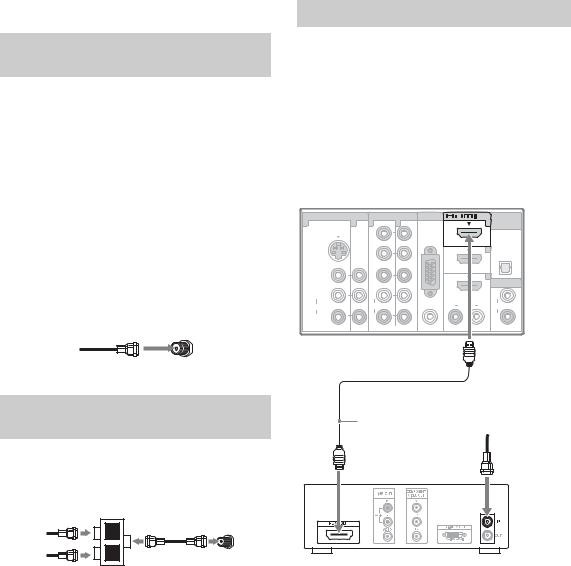
HD Cable Box/HD Satellite Box
You can enjoy high-definition programming by subscribing to a high-definition cable service or a high-definition satellite service. For the best possible picture, make sure you connect this equipment to your TV via the HDMI or component video (with audio) input on the back of your TV.
Shown with HDMI Connection
Rear of TV
|
VIDEO IN |
COMPONENT IN |
PC IN |
IN |
DIGITAL |
|
1 |
3 |
1 |
2 |
|
1 |
OUT |
|
(OPTICAL) |
|||||
|
|
Y |
|
RGB |
|
|
|
|
|
|
|
|
|
|
S VIDEO |
PB |
|
|
3 |
|
|
|
|
|
|
|
|
|
VIDEO |
PR |
|
|
4 |
AUDIO OUT |
|
|
|
|
|
|
|
|
L |
L |
|
|
|
L |
|
(MONO) |
|
|
|
||
|
AUDIO |
AUDIO |
|
AUDIO |
R AUDIO L |
AUDIO |
|
R |
R |
|
|
|
R |
|
|
(1080p/1080i/720p/480p/480i) |
|
|
(VAR/FIX) |
|
HDMI cable
CATV/Satellite antenna cable
HD cable box/
HD satellite box
12
Shown with DVI Connection
|
|
|
|
|
|
|
CATV/Satellite |
|
|
|
|
|
|
DVI-to-HDMI |
antenna cable |
|
|
|
|
|
|
|
|
Rear of TV |
|
|
|
|
|
cable |
|
|
|
|
|
|
|
|
|
VIDEO IN |
|
COMPONENT IN |
PC IN |
IN |
DIGITAL |
|
|
1 |
3 |
1 |
2 |
|
1 |
OUT |
|
|
(OPTICAL) |
HD cable box/ |
|||||
|
|
Y |
|
RGB |
|
|
|
|
|
|
|
|
|
HD satellite box |
|
S VIDEO |
|
PB |
|
|
3 |
|
|
|
|
|
|
|
|||
|
|
|
|
|
|
|
|
VIDEO |
|
PR |
|
|
4 |
AUDIO OUT |
|
|
|
|
|
|
|
|
|
L |
|
L |
|
|
|
L |
|
(MONO) |
|
|
|
|
|
||
AUDIO |
|
AUDIO |
|
AUDIO |
R AUDIO L |
AUDIO |
|
R |
|
R |
|
|
|
R |
|
|
|
(1080p/1080i/720p/480p/480i) |
|
|
(VAR/FIX) |
|
|
AUDIO-R (red) 


AUDIO-L (white)
Audio cable
~
•If the equipment has a DVI jack and not an HDMI jack, connect the DVI jack to the HDMI IN 4 (with DVI-to-HDMI cable or adapter) jack and connect the audio jack to the AUDIO IN (L/R) jacks of HDMI IN 4. For details, see page 11.
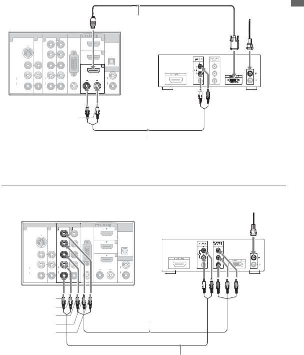
Shown with Component Connection
CATV/Satellite antenna cable
Rear of TV
1 |
VIDEO IN |
COMPONENT IN PC IN |
IN |
DIGITAL |
HD cable box/ |
|
3 |
1 |
2 |
1 |
(OPTICAL) |
||
|
|
|
|
|
OUT |
|
|
|
Y |
RGB |
|
|
HD satellite box |
|
|
|
|
|
|
|
|
S VIDEO |
PB |
|
3 |
|
|
|
|
|
|
|
|
|
|
VIDEO |
PR |
|
4 |
AUDIO OUT |
|
|
|
|
|
|
|
|
L |
L |
|
|
|
|
L |
(MONO) |
|
|
|
|
||
AUDIO |
AUDIO |
AUDIO |
R |
AUDIO |
L |
AUDIO |
R |
R |
|
|
|
|
R |
(1080p/1080i/720p/480p/480i) |
(VAR/FIX) |
AUDIO-R (red) 


AUDIO-L (white)
PR (red)
Component video cable
PB (blue)
Y (green)
Audio cable
Started Getting
(Continued)
13
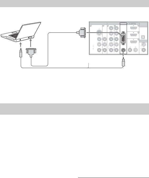
PC
Use the TV as a monitor for your PC by connecting a HD15 to HD15 cable as shown below. This TV can also be connected to a PC with a DVI or HDMI output. (Refer to the separate Quick Setup Guide.)
 HD15-HD15 cable (analog RGB)
Rear of TV
|
VIDEO IN |
COMPONENT IN |
PC IN |
IN |
DIGITAL |
|
1 |
3 |
1 |
2 |
|
1 |
OUT |
|
(OPTICAL) |
|||||
|
|
Y |
|
|
|
|
|
|
|
|
RGB |
|
|
|
S VIDEO |
PB |
|
|
3 |
|
|
|
|
|
|
|
|
|
VIDEO |
PR |
|
|
4 |
AUDIO OUT |
|
|
|
|
|
|
|
|
L |
L |
|
|
|
L |
|
(MONO) |
|
|
|
||
|
AUDIO |
AUDIO |
|
AUDIO |
R AUDIO L |
AUDIO |
|
R |
R |
|
|
|
R |
|
|
(1080p/1080i/720p/480p/480i) |
|
|
(VAR/FIX) |
|
Audio cable (stereo mini plugs)
~
•Connect the PC IN jack to the PC using an HD15HD15 cable with ferrite core (analog RGB) and audio cable (see page 11).
PC Input Signal Reference Chart
•If the PC is connected to the TV and no signal has been input from the PC for more than 30 seconds, the TV enters the standby mode automatically (see page 42).
After connecting the PC to the TV, set the output signal from the PC according to the supported resolutions and timings indicated below.
Supported resolutions |
|
|
Horizontal |
Vertical |
Standard |
||
Signal |
Horizontal |
× |
Vertical |
||||
frequency (kHz) |
frequency (Hz) |
|
|||||
|
(Pixel) |
|
(Line) |
|
|||
|
|
|
|
|
|||
VGA |
640 |
× |
480 |
31.5 |
60 |
VGA |
|
|
|
|
|
|
|
|
|
|
640 |
× |
480 |
37.5 |
75 |
VESA |
|
|
|
|
|
|
|
|
|
|
720 |
× |
400 |
31.5 |
70 |
VGA-T |
|
|
|
|
|
|
|
|
|
SVGA |
800 |
× |
600 |
37.9 |
60 |
VESA Guidelines |
|
|
|
|
|
|
|
|
|
|
800 |
× |
600 |
46.9 |
75 |
VESA |
|
|
|
|
|
|
|
|
|
XGA |
1,024 |
× |
768 |
48.4 |
60 |
VESA Guidelines |
|
|
|
|
|
|
|
|
|
|
1,024 |
× |
768 |
56.5 |
70 |
VESA |
|
|
|
|
|
|
|
|
|
|
1,024 |
× |
768 |
60.0 |
75 |
VESA |
|
|
|
|
|
|
|
|
|
WXGA |
1,280 |
× |
768 |
47.4 |
60 |
VESA |
|
|
|
|
|
|
|
|
|
|
1,280 |
× |
768 |
47.8 |
60 |
VESA |
|
|
|
|
|
|
|
|
|
|
1,280 |
× |
768 |
60.3 |
75 |
|
|
|
|
|
|
|
|
|
|
|
1,360 |
× |
768 |
47.7 |
60 |
VESA |
|
|
|
|
|
|
|
|
|
SXGA |
1,280 |
× |
1,024 |
64.0 |
60 |
VESA |
|
|
|
|
|
|
|
|
|
HDTV |
1,920 |
× |
1,080 |
67.5 |
60 |
CEA-861* |
|
|
|
|
|
|
|
|
|
~
•This TV’s PC input does not support Sync on Green or Composite Sync.
•This TV’s PC VGA input does not support interlaced signals.
•Your PC must support one of the above PC input signals to display on the television.
•For the best picture quality, it is recommended to use the signals (boldfaced) in the above chart with a 60 Hz vertical frequency. In plug and play, signals with a
60 Hz vertical frequency will be detected automatically. (PC reboot may be necessary.)
*The 1080p timing when applied to the HDMI input will be treated as a video timing and not PC timing. This affects Picture settings, Wide Mode settings, and PIP function. To view PC content set Picture Mode to Custom, Wide Mode to Full, and Display Area to Full Pixel.
14

Other Equipment
Personal |
Blu-ray |
DVD |
Digital |
Digital |
Audio |
Disc Player/ |
satellite |
||||
computer |
“PS3” |
player |
receiver |
cable box |
system |
|
|
|
|
|
|
|
|
|
|
|
|
IN
2
VIDEO IN
2
VIDEO
L (MONO)
AUDIO
Rear of TV
R
VIDEO IN |
COMPONENT IN PC IN |
1 |
3 |
1 |
2 |
|
|
Y |
RGB |
|
|
|
|
S VIDEO |
|
PB |
|
|
|
|
|
VIDEO |
|
PR |
|
L |
|
L |
|
(MONO) |
|
|
|
AUDIO |
|
AUDIO |
AUDIO |
R |
|
R |
|
|
|
(1080p/1080i/720p/480p/480i) |
|
IN |
DIGITAL |
1 |
OUT |
(OPTICAL) |
3
|
|
|
4 |
|
|
|
AUDIO OUT |
|
|
|
L |
R |
AUDIO |
L |
AUDIO |
|
|
|
R |
|
|
|
(VAR/FIX) |
CABLE/ANTENNA
Started Getting
CABLE/ANTENNA
VCR |
Digital |
Analog |
Digital audio |
Camcorder |
|
recorder |
audio |
equipment |
|
Game |
|
equipment |
|
|
|
(A/V Receiver/Home Theater) |
|
||
system |
|
|
|
|
~
• Refer to the Quick Setup Guide (supplied) when connecting other equipment to your TV.
15
Loading...