


Sony BKDW-509, BKDW-514, BKDW-515, BKDW-505-506, DVW-500P-1 User Manual
...DIGITAL VIDEOCASSETTE RECORDER
DVW-A500/1
DVW-A500P/1
DVW-500/1
DVW-500P/1
CONTROL PANEL
BKDW-515
ANALOG COMPOSITE DECODER BOARD
BKDW-505/506
AUDIO PROGRAM PLAY BOARD
BKDW-507
PARALLEL (50P) INTERFACE KIT
BKDW-509
CONTROL PANEL
BKDW-514
OPERATION MANUAL [ English ] 1st Edition (Revised 3)
Serial No. 50001 and Higher (DVW-A500/1) Serial No. 50001 and Higher (DVW-A500P/1) Serial No. 50001 and Higher (DVW-500/1) Serial No. 50001 and Higher (DVW-500P/1) Serial No. 10001 and Higher (BKDW-515)

WARNING
To prevent fire or shock hazard, do not expose the unit to rain or moisture.
To avoid electrical shock, do not open the cobinet. Refer servicing to qualified personnel only.
This symbol is intended to alert the user to the presence of uninsulated “dangerous voltage” within the product’s enclosure that may be of sufficient magnitude to constitute a risk of electric shock to persons.
This symbol is intended to alert the user to the presence of important operating and maintenance (servicing) instructions in the literature accompanying the appliance.
For the customers in Europe (For BKDW-515)
This product with the CE marking complies with the EMC Directive (89/336/EEC) issued by the Commission of the European Community.
Compliance with this directive implies conformity to the following European standards:
•EN55103-1: Electromagnetic Interference (Emission)
•EN55103-2: Electromagnetic Susceptibility (Immunity) This product is intended for use in the following Electromagnetic Environment:
E4 (controlled EMC environment, ex. TV studio).
For the customers in the United Kingdom
WARNING
THIS APPARATUS MUST BE EARTHED
IMPORTANT
The wires in this mains lead are coloured in accordance with the following code:
Green-and-yellow: Earth Blue: Neutral
Brown: Live
As the colours of the wires in the mains lead of this apparatus may not correspond with the coloured markings identifying the terminals in your plug, proceed as follows: The wire which is coloured green-and-yellow must be connected to the terminal in the plug which is marked by the letter E or by the safety earth symbol Y or coloured green or green-and-yellow.
The wire which is coloured blue must be connected to the terminal which is marked with the letter N or coloured black.
The wire which is coloured brown must be connected to the terminal which is marked with the letter L or coloured red.
For the customers in U.S.A.
This equipment has been tested and found to comply with the limits for a Class A digital device, pursuant to Part 15 of the FCC Rules. These limits are designed to provide reasonable protection against harmful interference when the equipment is operated in a commercial environment. This equipment generates, uses, and can radiate radio frequency energy and, if not installed and used in accordance with the instruction manual, may cause harmful interference to radio communications. Operation of this equipment in a residential area is likely to cause harmful interference in which case the user will be required to correct the interference at his or her own expense.
You are cautioned that any changes or modifications not expressly approved in this manual could void your authority to operate this equipment.
The shielded interface cable recommended in this manual must be used with this equipment in order to comply with the limits for a digital device pursuant to Subpart B of Part 15 of FCC Rules.
WARNING: Using this unit at a voltage other than 120 V may require the use of a different line cord or attachment plug, or both. To reduce the risk of fire or electric shock, refer servicing to qualified service personnel.

Table of Contents
|
|
|
|
|
|
|
|
|
|
|
|
|
|
Chapter 1 |
|
|
|
...........................................................................................1-1 Features |
1-1 |
|
Overview |
|
|
|
1-1-1 Features of the DVW-A500/1, A500P/1, 500/1 and 500P/1 .. |
1-1 |
|
|
|
|
|
|
1-1-2 Features of the BKDW-515 ................................................... |
1-3 |
|
|
|
|
|
1-2 Optional Accessories ...................................................................... |
1-5 |
|
|
|
|
|||
|
|
|
|
|
|
|
Chapter 2 |
|
|
|
2-1 Control Panel .................................................................................. |
2-1 |
|
Locations and Functions |
|
|
|
2-1-1 Upper Control Panel ............................................................... |
2-2 |
|
of Parts and Controls |
|
|
|
2-1-2 Lower Control Panel (Menu Operations Section) .................. |
2-5 |
|
|
|
|
|
|
2-1-3 Lower Control Panel (Editing Operations Section) ............... |
2-7 |
|
|
|
|
|
2-1-4 Lower Control Panel (Tape Transport Section) ..................... |
2-9 |
|
|
|
|
|
2-1-5 Lower Control Panel (Search Operations Section) .............. |
2-11 |
|
|
|
|
|
2-2 System Set-Up Panel .................................................................... |
2-13 |
|
|
|
|
|
2-3 Connector Panel ........................................................................... |
2-14 |
|
|
|
|
|||
|
|
|
|
|
|
|
Chapter 3 |
|
|
|
3-1 Connecting External Equipment .................................................. |
3-1 |
|
Setting Up the VTR |
|
|
|
3-1-1 Making Digital Connections .................................................. |
3-1 |
|
|
|
|
|
|
3-1-2 Making Analog Connections ................................................. |
3-2 |
|
|
|
|
|
3-2 Reference Signals for Video Output and Servo System .............. |
3-3 |
|
|
|
|
|
3-2-1 External Sync Signal for the Internal Reference Video Signal |
|
|
|
|
|
|
Generator ................................................................................ |
3-3 |
|
|
|
|
|
3-2-2 Reference Signal for the Servo System.................................. |
3-4 |
|
|
|
|
|
3-2-3 Reference Signals Connections .............................................. |
3-5 |
|
|
|
|
|
3-3 Handling Cassettes ......................................................................... |
3-7 |
|
|
|
|
|
3-3-1 Recommended Cassettes ........................................................ |
3-7 |
|
|
|
|
|
3-3-2 Inserting and Ejecting Cassettes ............................................ |
3-7 |
|
|
|
|
|
3-3-3 Preventing Accidental Erasure ............................................... |
3-8 |
|
|
|
|
|
|
|
Chapter 4 |
|
|
|
4-1 Registering and Storing Menu Settings ........................................ |
4-1 |
|
Menu Settings |
|
|
|
4-1-1 Menu Configuration ............................................................... |
4-1 |
|
|
|
|
|
|
4-1-2 Changing Menu Settings ........................................................ |
4-2 |
|
|
|
|
|
4-1-3 Registering Items to the PF1/2 Menus ................................... |
4-3 |
|
|
|
|
|
4-1-4 VTR Memory Bank Function ................................................ |
4-4 |
|
|
|
|
|
4-1-5 IC Memory Card Function ..................................................... |
4-6 |
|
|
|
|
|
4-1-6 Adding Titles to the Data ..................................................... |
4-11 |
|
|
|
|
|
4-1-7 Details on VTR Memory Bank and IC Memory Card |
|
|
|
|
|
|
Functions .............................................................................. |
4-12 |
|
|
|
|
|
4-1-8 IC Memory Card Data Compatibility Among |
|
|
|
|
|
|
the DVW-A500/1 and DVW-500/1 Series VTRs ................ |
4-12 |
|
|
|
|
|
4-2 HOME Menu ................................................................................ |
4-13 |
|
|
|
|
|
4-2-1 Setting the Preread Function (PRE READ) ......................... |
4-14 |
|
|
|
|
|
4-2-2 Simultaneous Playback During Recording (CONFI)........... |
4-14 |
|
|
|
|
|
4-2-3 Selecting the Edit Mode and Edit Channel |
|
|
|
|
|
|
(ASSEMBLE to INS CUE) .................................................. |
4-14 |
|
|
|
|
|
4-2-4 Setting Record Inhibit Mode (REC INH) ............................ |
4-15 |
|
|
|
|
|
4-2-5 Selecting the Monitor Mode (PB/EE) .................................. |
4-15 |
|
|
|
|
|
4-2-6 Outputting Still-Pictures (FREEZE) .................................... |
4-15 |
(Continued) |
|
|
|
4-2-7 Selecting the Capstan Servo Lock Mode (CAP LOCK) ...... |
4-16 |
|
|
|
|
|
|
|
|
Contents of Table
Table of Contents |
1 |

Contents of Table
Table of Contents
Chapter 4
Menu Settings
|
|
|
...........................4-2-8 Setting the Preroll Time (P-ROLL TIME) |
4-16 |
|
|
|
4-2-9 Selecting DMC Playback (DMC) ........................................ |
4-17 |
|
|
|
4-2-10 Selecting Program Playback (P.PLAY) .............................. |
4-17 |
|
|
|
4-2-11 Recalling Edit Points (LAST EDIT) ................................... |
4-17 |
|
|
|
4-3 TC Menu ....................................................................................... |
4-18 |
|
|
|
4-3-1 Setting the Time Data (TIMER SEL/RESET/SET/HOLD) |
4-19 |
|
|
|
4-3-2 Setting the Time Code Reader (TC SEL) ............................ |
4-21 |
|
|
|
4-3-3 Setting the Time Code Generator |
|
|
|
|
(TCG SOURCE/MODE) ..................................................... |
4-21 |
|
|
|
4-3-4 Selecting the Time Code Running Mode (RUN MODE) .... |
4-22 |
|
|
|
4-3-5 Selecting the Drop Frame Mode (DF/NDF) (DVW-A500/1 and |
|
|
|
|
500/1 only) ........................................................................... |
4-22 |
|
|
|
4-3-6 Recording VITC (VITC) ...................................................... |
4-23 |
|
|
|
4-3-7 Selecting CTL Display Mode (TAPE TIMER) ................... |
4-23 |
|
|
|
4-3-8 ID Preset (ID PRESET) ....................................................... |
4-23 |
|
|
|
4-3-9 Superimposition of Character Information |
|
|
|
|
(CHARA SUPER/H-POS/V-POS) ...................................... |
4-23 |
|
|
|
4-3-10 Setting the VITC Insertion Line (VITC POS-1/POS-2) ..... |
4-26 |
|
|
|
4-4 CUE Menu .................................................................................... |
4-27 |
|
|
|
4-4-1 Selecting a Multi-Cue Mode ................................................ |
4-28 |
|
|
|
4-4-2 Registering Cue Points ......................................................... |
4-28 |
|
|
|
4-4-3 Erasing Cue Point Data ........................................................ |
4-30 |
|
|
|
4-4-4 Prerolling to a Cue Point ...................................................... |
4-31 |
|
|
|
4-4-5 Changing a Cue Point Into an Edit Point ............................. |
4-32 |
|
|
|
4-4-6 Backspace Editing ................................................................ |
4-32 |
|
|
|
4-5 PF1 Menu (Factory Settings) ....................................................... |
4-33 |
|
|
|
4-5-1 Selecting the Input Video Signal |
|
|
|
|
(VIDEO IN) ......................................................................... |
4-34 |
|
|
|
4-5-2 Selecting the Reference Signal |
|
|
|
|
(OUT REF) .......................................................................... |
4-34 |
|
|
|
4-5-3 Switching the Control of the Digital Video Processor |
|
|
|
|
(PROC CONTRL)................................................................ |
4-34 |
|
|
|
4-5-4 Adjusting the Output Video Signal |
|
|
|
|
(VIDEO GAIN to SYSTEM SC) ......................................... |
4-34 |
|
|
|
4-6 PF2 Menu (Factory Settings) ....................................................... |
4-36 |
|
|
|
4-6-1 Selecting the Audio Input Signal |
|
|
|
|
(A-IN ALL to A-IN CH4) .................................................... |
4-37 |
|
|
|
4-6-2 Setting the Dolby NR System |
|
|
|
|
(DOLBY NR) (DVW-A500/1 Series Only) ........................ |
4-37 |
|
|
|
4-6-3 Setting Emphasis (EMPHASIS) .......................................... |
4-37 |
|
|
|
4-6-4 Selecting the Monitor Output Signal |
|
|
|
|
(MON-L SEL/MON-R SEL) ............................................... |
4-37 |
|
|
|
4-7 SET UP Menu ............................................................................... |
4-38 |
|
|
|
4-7-1 VTR SETUP Menu .............................................................. |
4-40 |
|
|
|
4-7-2 PANEL SETUP Menu ......................................................... |
4-42 |
|
|
|
|
|
2 Table of Contents

|
|
|
|
|
|
|
|
|
|
Chapter 5 |
5-1 |
................................................................Preparing for Recording |
5-1 |
|
Recording/Playback |
|
5-1-1 Setting Switches and Menus .................................................. |
5-1 |
|
|
|
5-1-2 |
Selecting Audio Signals ......................................................... |
5-2 |
|
|
5-1-3 |
Adjusting the Audio Recording Level ................................... |
5-3 |
|
|
5-1-4 |
Monitoring Simultaneous Playback of Video and Audio Signals |
|
|
|
|
Being Recorded .................................................................... |
5-4 |
|
|
5-1-5 |
Recording Analog Audio ....................................................... |
5-4 |
|
5-2 |
Recording ........................................................................................ |
5-5 |
|
|
5-3 |
Preparing for Playback .................................................................. |
5-6 |
|
Chapter 6
Editing
Chapter 7
Maintenance
|
5-3-1 Setting Switches and Menus .................................................. |
5-6 |
|
|
5-3-2 Adjusting the Audio Playback Level ..................................... |
5-6 |
|
|
5-4 Playback .......................................................................................... |
5-7 |
|
|
5-4-1 Normal-Speed Playback ......................................................... |
5-7 |
|
|
5-4-2 Variable Speed Playback in Jog/Shuttle/Variable Modes ...... |
5-8 |
|
|
5-4-3 Capstan Override Playback .................................................. |
5-10 |
|
|
5-4-4 DMC Playback ..................................................................... |
5-10 |
|
|
5-4-5 Program Playback ................................................................ |
5-13 |
|
|
6-1 Basic Automatic Editing ................................................................ |
6-1 |
|
|
6-1-1 Overview of Automatic Editing ............................................. |
6-1 |
|
|
6-1-2 Setting Switches and Menus .................................................. |
6-2 |
|
|
6-1-3 Selecting the Edit Mode ......................................................... |
6-3 |
|
|
6-1-4 Setting Edit Points .................................................................. |
6-3 |
|
|
6-1-5 Confirming Edit Points .......................................................... |
6-7 |
|
|
6-1-6 Cuing Up and Prerolling ........................................................ |
6-7 |
|
|
6-1-7 Previewing ............................................................................. |
6-8 |
|
|
6-1-8 Modifying Edit Points ............................................................ |
6-9 |
|
|
6-1-9 Performing Automatic Editing ............................................. |
6-11 |
|
|
6-2 Advanced Automatic Editing ...................................................... |
6-14 |
|
|
6-2-1 Performing DMC Editing..................................................... |
6-14 |
|
6-2-2 |
Performing Quick Editing .................................................... |
6-16 |
|
6-2-3 |
Performing Consecutive Editing .......................................... |
6-17 |
|
|
6-2-4 Performing Preread Editing ................................................. |
6-18 |
|
|
6-3 Manual Editing ............................................................................. |
6-19 |
|
|
7-1 Head Cleaning ................................................................................ |
7-1 |
|
|
7-2 Moisture Condensation .................................................................. |
7-2 |
|
|
|
|
|
|
|
|
|
Contents of Table
Table of Contents |
3 |

Contents of Table
Table of Contents
Appendix
|
|
.........................................................................................Specifications |
A-1 |
|
|
|
Glossary ................................................................................................. |
A-5 |
|
|
|
Menu List .............................................................................................. |
A-7 |
|
|
|
|
Items Related to the Hours Meter (Hs) ........................................... |
A-7 |
|
|
|
Items Related to VTR Operations (000s) ........................................ |
A-8 |
|
|
|
Items Related to Operation Panels (100s) ..................................... |
A-10 |
|
|
|
Items Related to Remote Interface (200s) ..................................... |
A-14 |
|
|
|
Items Related to Editing (300s) ..................................................... |
A-15 |
|
|
|
Items Related to Prerolling (400s) ................................................. |
A-19 |
|
|
|
Items Related to Recording Protection (500s) .............................. |
A-20 |
|
|
|
Items Related to the Time Code Generator (600s) ........................ |
A-21 |
|
|
|
Items Related to the Video Control (700s) .................................... |
A-24 |
|
|
|
Items Related to the Audio Control (800s) ................................... |
A-31 |
|
|
|
Items Related to Digital Process (900s) ........................................ |
A-34 |
|
|
|
Items Set by Switches on Models DVW-A500, A500P, 500, |
|
|
|
|
and 500P (Ks) ...................................................................... |
A-37 |
|
|
Index ........................................................................................................ |
I-1 |
|
|
|
Function Button List (Factory Settings) ................................. |
Last page |
|
|
|
|
|
|
4 Table of Contents

1-1 Features
1-1-1 Features of the DVW-A500/1,
A500P/1, 500/1 and 500P/1
The DVW-A500/1, A500P/1, 500/1, and 500P/1 Digital Videocassette Recorders adopt the Digital Betacam format, and are differentiated as follows:
•The DVW-A500/1 and DVW-A500P/1 are capable of playing back analog Betacam and Betacam SP format cassette tapes.
•The DVW-500/1 and DVW-500P/1 are not compatible with either the analog Betacam or Betacam SP formats.
The DVW-A500/1 and 500/1 can be used in the NTSC color system while the DVW-A500P/1 and 500P/1 can be used in the PAL color system, though they both adopt a component format.
Digital Betacam Format
The DVW-A500/1 series and DVW-500/1 series adopt the newly developed Digital Betacam format as an extension of the Betacam/Betacam SP format. The Digital Betacam format makes the most of the available recording area to achieve high-quality digital recording, while maintaining analog Betacam tape playback compatibility. The following have been developed for this purpose:
•Coefficient recording system
•Powerful error correction system
•High-quality precision heads and drum with DT® (Dynamic Tracking) heads
•New auto tracking system
Together, these allow 120 minutes or more of recording time on half-inch Digital Betacam (L-size) cassettes the same size as those for conventional Betacam and Betacam SP.
Overview of digial signal processing
Digital video signal processing is based on the 4:2:2 component digital D-1 format and CCIR 601 standard quantization. In addition, the data rate is compressed with the coefficient recording system. Digital audio signals are processed in full bits conforming to the AES/EBU format.
Input interface
The component serial digital interface, conforming to SMPTE 259M/EBU T.3267/CCIR 656-III standards, handles component video signals and 4-channel digital audio signals with a single BNC coaxial cable. Both
analog component signals and composite signals (with the BKDW-505/506) are digitized into CCIR 601 standard parallel data.
Audio data from the AES/EBU digital interface or A/D converted data from analog input can be selected for recording.
Bit rate reduction encoder
Video data are suppressed to about half by a newly developed coefficient recording system, whose key processes include field shuffling, blocking, DCT (Discrete Cosine Transform), quantizing, and variable length coding.
ECC encoder
The outer ECC (Error Correction Code) is added to the compressed video and audio data, followed by the inner ECC, ID data, and sync data. The ReedSolomon code is employed in this error correction system.
Channel coding
Video and audio data with the ECC added are recorded in the form of serial data. The Digital Betacam format adopts a scrambled NRZI channel coding system that is superior in off-track and noise characteristics.
Playback signal processing
The playback digital data are equalized by auto EQ circuits and error-corrected by powerful inner and outer ECC, which can correct most data disturbed by noise and dropouts in the reproduced signal. Data that cannot be corrected further are compensated by error concealment circuits.
Output interface
Component video data are converted into serial data and multiplexed with audio data, then output in the serial digital interface format.
For analog output, component video data are D/A converted into an analog component signal, while they are encoded into composite digital, then D/A converted into analog composite signal.
For audio outputs, the AES/EBU digital interface and D/A converted analog audio are available.
1 Chapter
OverChapter1 Oveview view
Chapter 1 Overview 1-1

Overview 1 Chapter
1-1 Features
Advanced Recording and Playback
Functions
High-quality digital recording
The DVW-A500/1 series and DVW-500/1 series adopt component digital video and a four-channel, 20-bit digital audio recording system using an AES/EBU format with a wide dynamic range. A digital signal processing system that includes an advanced error correction and concealment system that are unique to digital Betacam provides superb video and audio quality, while the adjusting and setting of a built-in digital video processor ensures the output of precise and stable video signals.
Playback compatibility with analog Betacam and Betacam SP (DVW-A500/1 series only)
The DVW-A500/1 series provide playback capability with tapes recorded on the Betacam SP VTRs, so that Betacam users can upgrade to a digital environment while enjoying continued access to the enormous analog Betacam archives.
Noiseless playback with DT heads
Using the playback DT heads, you can perform noiseless playback at 54 speeds ranging from –1 to +3 times normal speed, including still-picture playback. Noiseless playback is also supported in the case of both digital and analog Betacam playback.
Video and audio confidence heads
Video and audio confidence heads enable you to play back video and audio signals on channels 1 to 4 while recording, to check the quality of the recording.
Internal time code generator and reader
The internal time code generator allows you to record LTC/VITC time codes and user bits together with video and audio signals. Time codes and user bits are read by the internal time code reader during playback.
Computer servo system
Computer-controlled servo motors provide direct drive for the drum, capstan, and two reels, enabling quick and accurate tape access.
Capstan override function
You can adjust the playback speed by ±15% to ensure synchronization between, for example, two VTRs playing back the same program.
Independent level controls
The recording and playback levels of each of the four audio channels can be set indepenently during monitoring of audio level meters.
Features for Ease of Operation
Compact, lightweight, low power consumption
The VTR is small and light enough to be used in outside broadcast vans or in EFP (Electronic Field Production) assignments.
Remote control operation
The VTR has a serial RS-422A 9-pin connector to allow control of the VTR by an external control unit through RS-422A communications.
The VTR also comes with 9-pin REMOTE1-IN(9P) and OUT(9P) connectors to support bridge connection of multiple DVW-A500/1 or DVW-500/1 series units or other VTRs equipped with 9-pin remote connectors for simultaneous operations.
Furthermore, by using the optional BKDW-509 Parallel (50-pin) Interface Kit, you can control the VTR from an external control unit with a parallel interface.
Digital hours meter
Three different hour displays and one cycle count display are supported, showing total elapsed time since the VTR was turned on, total drum revolution time, total tape running time and total number of threadings and unthreadings.
Self-diagnosis
When enabled through the maintenance menu, any malfunction causes the VTR to perform self-diagnosis, after which it displays the relevant error code in the display.
Easy-to-maintain plug-in boards
The VTR uses plug-in circuit boards to simplify servicing and inspection.
Mountable in standard 19-inch rack
The unit can be mounted in an EIA-standard 19-inch rack.
For rack mounting, refer to the Installation Manual.
1-2 Chapter 1 Overview

1-1-2 Features of the BKDW-515
The BKDW-515 Control Panel provides six menu screens corresponding to the six operation modes to allow fast and easy adjustment of necessary settings, as well as the ability to store menu settings to a memory card for later recall.
Menu-driven operations for a variety of purposes
Six types of menus appear on the BKDW-515’s 90 × 72 mm (35/8 inches × 27/8 inches) display, and are set using the 10 /function buttons to the left and at the bottom of the display.
HOME menu
Use this menu to make the basic settings for recording, playback, and editing operations, and to select channels to be edited during insert editing.
TC menu
Use this menu to make time code settings.
CUE menu
Use this menu to set up to 100 cue points. In page mode, 10 cue points per page can be set on a total of 10 pages.
PF1/PF2 (Personal Function) menus
Use these menus to register up to 40 of the most frequently used items from the other menus (up to ten items each can be registered to PF1, ALT+PF1, PF2 and ALT+PF2). You can display the registerable items by pressing the [F4] (PF1&2 ASSIGN) button in the SET UP menu.
SET UP menu
•Use the VTR BANK menu to memorize menu settings of up to 8 pages.
•Use the MEMORY CARD menu to store current settings of the VTR and up to 8 pages of the contents of the VTR memory bank to an IC memory card.
•Use the scrollable PF1&2 ASSIGN menu to display the items that can be registered in the PF1/PF2 menus, and to select and register the most frequently used menu items.
•Use the scrollable VTR SETUP menu to display the items necessary for making initial settings, and to directly change settings without registering them to the function buttons for each menu.
•Use the PANEL SETUP menu to set control panel operations, such as the keyboard sound output.
MAINTENANCE menu
Use this menu to access the maintenance functions in conjunction with a video monitor.
For details, refer to the Installation and Maintenance Manual.
A full complement of storage/recall functions
These functions allow you to store and recall menu settings in either the VTR’s internal memory banks or IC memory cards by title.
VTR memory banks
These memory banks allow you to store up to eight pages of VTR settings in addition to the current VTR settings. Factory settings are also stored here, allowing the VTR to be reset to these values at any time.
IC memory cards
Each IC memory card can hold the current VTR settings as well as up to eight pages of settings. A single IC memory card thus allows you to store and recall the entire contents of the VTR memory banks.
Title function
This function allows you to add titles when storing data to the VTR memory bank or IC memory card, thus facilitating data retrieval and management.
A full range of editing functions
You can connect two DVW-A500/1 or DVW-500/1 series units to enable automatic or manual editing in either assemble or insert mode. The VTR also features a full range of editing functions, including preview, review, preroll, and the setting or changing of edit points.
Quick access to edit points
The following methods are provided for the setting of edit points:
•Multi-cuing for up to 100 edit points
•Search dial with shuttle and jog functions
•Direct input through numeric buttons
Overview 1 Chapter
Chapter 1 Overview 1-3

Overview 1 Chapter
1-1 Features
DMC (Dynamic Motion Control) editing
Using the DT® (Dynamic Tracking ) heads, you can play back a section of an edit at speeds between –1 and +3 times normal speed, and store the speed variation in memory for later use in automatic editing.
Split editing
In insert mode, you can set audio and video edit points separately.
Preread editing
You can perform preread editing using video or digital audio signals recorded on the tape as the edit source for insert editing.
A variety of audio editing modes
You can select cut-in editing, cross-fade editing, and fade in/out editing for the audio signals.
Display of duration between edit points
After edit point data have been set, you can display the duration between any two IN, OUT, AUDIO IN, or AUDIO OUT points by simultaneously pressing two buttons corresponding to those edit points.
Digital time counter
The time counter display shows CTL and time codes (LTC/VITC1)), or user bits data to enable the precise setting of edit points.
..........................................................................................................................................................................................................
1)LTC (Longitudinal Time Code)
Time code recorded on a longitudinal track
VITC (Vertical Interval Time Code)
Time code recorded on a video track during the vertical blanking interval
1-4 Chapter 1 Overview
1-2 Optional Accessories
The following accessories can be used with the DVWA500/1 series and DVW-500/1 series:
BKDW-505 (for NTSC video format)/BKDW506 (for PAL video format) Analog Composite Decoder Board
Converts in-coming analog composite video signals to digital signals. Allows bridge connection with other components.
BKDW-507 Audio Program Play Board
Enables the output of audio signals that retain their original pitch during program playback. Also stabilizes pictures during program playback.
BKDW-509 Parallel (50-pin) Interface Kit
Allows you to remotely control the DVW-A500/1 series or DVW-500/1 series from an external control unit with a parallel interface.
BKDW-514 Control Panel
When attached in place of the BKDW-515, this control panel makes the VTR equivalent to the DVWA500 series or DVW-500 series in function and capability.
Note
The BKDW-515 and the control panel of the DVWA500/1 or DVW-500/1 series cannot be installed in the BKDW-511 Control Panel Case.
References
In addition to this Operation Manual, the following manuals are available:
•Installation and Maintenance Manual (supplied with the DVW-A500/1 series, DVW-500/1 series or the BKDW-515)
Provides information necessary for users to maintain the control panel.
•Installation Manual (supplied with the DVW-A500/1 series or DVW-500/1 series)
Provides information necessary to install the VTR and its peripherals.
•Manitenance Manual Part 1 (supplied with the DVWA500/1 series or DVW-500/1 series)
Provides information necessary for users to maintain the VTR.
•Maintenance Manual Part 2 (available on request) Provides additional information to fully maintain the DVW-A500/1 series, DVW-500/1 series and the BKDW-515. Contains details on electrical adjustments, circuit diagrams, and other items.
Overview 1 Chapter
Chapter 1 Overview 1-5

1-1 Features
Overview 1 Chapter
1-6 Chapter 1 Overview
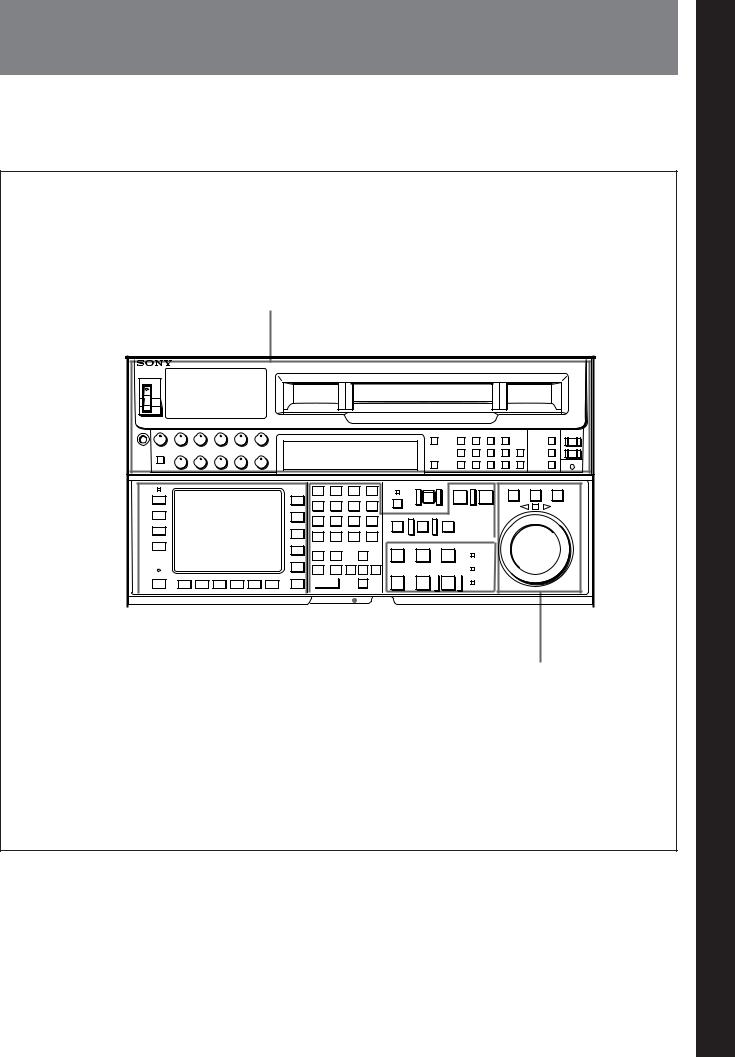
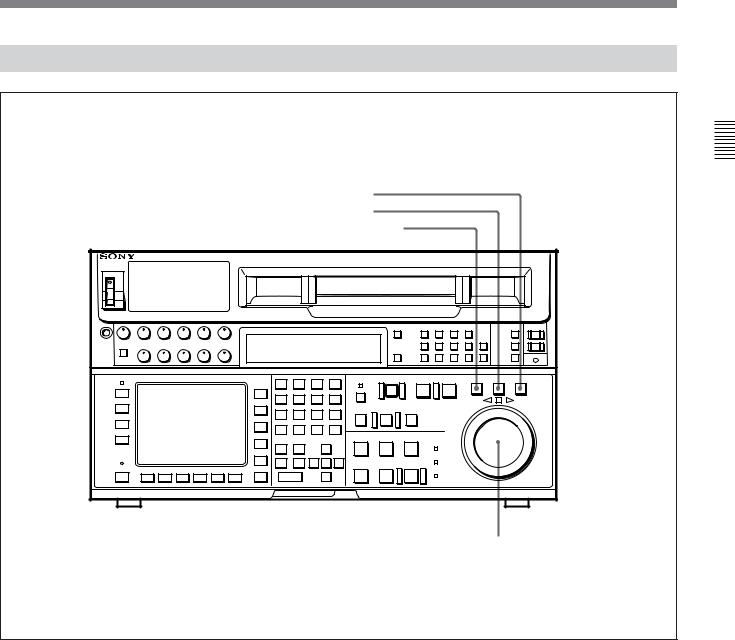
2-1 Control Panel
|
|
The control panel consists of the following sections: |
memory card insertion slot, editing operations |
• Upper control panel |
section, tape transport section and search operations |
• Lower control panel: menu operations section, IC |
section |
Upper control panel
Lower control panel
|
|
|
|
|
|
|
|
|
|
|
|
|
|
|
|
|
|
|
|
|
|
|
|
|
|
|
|
|
|
|
|
|
|
|
|
|
|
|
|
|
|
|
|
|
|
|
|
|
|
|
|
|
|
|
|
|
|
|
|
|
|
|
|
|
|
|
|
|
|
|
|
|
|
|
|
|
|
|
|
|
|
|
|
|
|
|
|
|
|
|
|
|
|
|
|
|
|
|
|
|
|
|
|
|
|
|
|
|
|
|
|
|
|
|
|
|
|
|
|
|
|
|
|
|
|
|
|
|
|
|
|
|
|
|
|
|
|
|
|
|
|
|
|
|
|
Menu operations section |
IC memory card |
|
|
|
|
|
Search operations section |
||||||||||||||
|
|
|
|
|
|
|
|
insertion slot |
|
|
|
|
|
|
|
|
|
|
|
||||
|
|
|
|
|
|
|
|
|
|
|
|
|
|
|
|
|
|
|
|
|
|
|
|
|
|
|
|
Editing operations section |
Tape transport section |
||||||||||||||||||
Control panel
2 Chapter
LocationsChapter
2
andLoctionsand FunctionsFnctionsof Partsand
ofPControls artsand
olsContr
Chapter 2 Locations and Functions of Parts and Controls |
2-1 |
Controls and Parts of Functions and Locations 2 Chapter
2-1 Control Panel
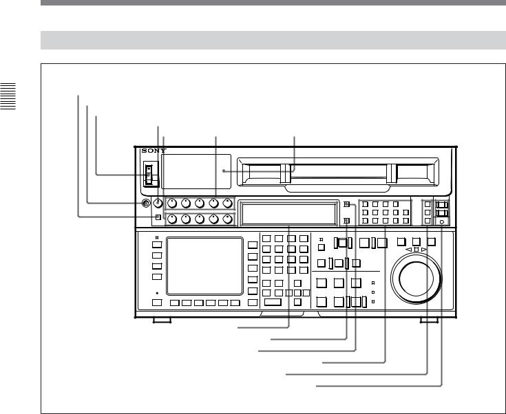
2-1-1 Upper Control Panel
1DISPLAY FULL/FINE button
2PHONES jack
3POWER switch
4PHONES level control
5 PB level 6REC level controls 7Audio level meters controls
8Indicator window
9MONITOR SELECT button
!ºINPUT SELECT button
!¡AUDIO INPUT/MONITOR SELECT buttons
!™VIDEO INPUT SELECT buttons
!£REMOTE buttons and RS-232C indicator
Upper control panel
1 DISPLAY FULL/FINE button
Changes the display range of the audio level meters. FULL: Display range is –60 to 0 dB (peak level = 0
dB) or –40 to +20 dB (peak level = +20 dB). Use 806. LEVEL METER SCALE in the VTR SETUP menu to select the range.
FINE: Displays the audio level in 0.25 dB increments. The center LED lights up in each meter as a signal level reference. When the level exceeds the maximum display value, the top LED lights up. When the level falls below the minimum display value, the bottom LED lights up.
2 PHONES jack
Connects stereo headphones with 8 Ω impedance for audio monitoring during recording, playback, and editing. Adjust the headphone output level with the PHONES level control.
3 POWER switch
Turns on the power. When the power is turned on, the audio level meters and menu display in the lower control panel light up.
2-2 |
Chapter 2 Locations and Functions of Parts and Controls |

4 PHONES level control
Adjusts the output level to the PHONES jack.
You can enable this control to simultaneously adjust the output level to the MONITOR OUTPUT connectors on the connector panel.
For details, refer to “5-1-2 Selecting Audio Signals” on page 5-2.
5 PB (playback) level controls
Adjust the level of the audio output for channels 1 to 4 and the cue channel.
Pull out the controls during playback to adjust the audio output for each channel. Push in again for factory-set levels (+4 dB output for a signal recorded at a reference level of 0 dB). When pushed in, the controls cannot adjust the audio output level.
6 REC (recording) level controls
Adjust the recording level for channels 1 to 4 and the cue channel.
Pull out the controls to adjust the recording level for each channel in E-E mode1). Push in again for the factory-set recording level (0 dB reference level for an input of +4 dB). When pushed in, the controls cannot adjust the recording level.
7 Audio level meters
Indicate the recording level in recording or E-E mode or the playback level in playback or CONFI mode. The display range can be changed by pressing the DISPLAY FULL/FINE button. The reference level is factory set at –20 dB, and the peak level at 0 dB.
8 Indicator window
The following indicators light up to indicate the VTR’s status.
Indicators and corresponding VTR status
Indicator |
Status |
DOLBY NR |
Lights up when the Dolby NR circuit is |
(DVW-A500/1 |
activated. |
series only) |
|
|
|
KEY INHIBIT |
Lights up when the [F1] (KEYINH) button |
|
in the PANEL SETUP menu is set to on. |
|
|
CHANNEL |
Indicates the playback signal condition. |
CONDITION |
Green: Playback signal is good. |
|
Yellow: Playback signal is less than |
|
good, but still reproducible. |
|
Red: Playback signal is poor. Head |
|
cleaning or internal inspection is |
|
necessary if the indicator lights up |
|
continuously. |
|
|
DIGITAL |
Lights up when a Digital Betacam |
|
cassette is inserted, and turns off when |
|
an analog Betacam cassette is inserted. |
|
|
LTC |
Lights up when the VTR is recording LTC |
|
signals or reading LTC signals during |
|
playback. Also lights up in E-E mode if |
|
you press the REC button while the [F6] |
|
(TCG SOURCE) button in the TC menu |
|
set to ext, allowing you to verify that the |
|
VTR is locked to an external time code. |
|
|
VITC |
Lights up when the VTR is reading VITC |
|
signals during playback, or when the VTR |
|
is in recording or E-E mode and the video |
|
input signal contains VITC signals. Also |
|
lights up when the [F10] (VITC) button in |
|
the TC menu is set to on and the VITC |
|
signals contained in the video signal are |
|
normal. |
|
|
9 MONITOR SELECT button
Selects the audio signal to be output at the MONITOR OUTPUT L/R connector(s). Press to light the button up, then press the AUDIO INPUT/MONITOR SELECT button(s) to specify which channel(s) are to be monitored at the MONITOR OUTPUT L or R connector. If you specify more than one channel to the same MONITOR OUTPUT connector, a mixed audio signal is output from that connector. This specification can also be done as a menu operation.
For details, refer to “4-6-4 Selecting the Monitor Output
Signal (MON-L SEL/MON-R SEL)” on page 4-37.
..........................................................................................................................................................................................................
1)E-E mode
An abbreviation for Electric-to-Electric mode. In this mode, video or audio input signals are passed and output only through the VTR’s internal circuitry, and not through the magnetic conversion system comprising tape and heads.
Controls and Parts of Functions and Locations 2 Chapter
Chapter 2 Locations and Functions of Parts and Controls |
2-3 |

Controls and Parts of Functions and Locations 2 Chapter
2-1 Control Panel
!º INPUT SELECT button
Selects the audio input signal. Press to light the button up, then press one of the AUDIO INPUT/MONITOR SELECT buttons to select the type and the channel of the audio signal.
SIF (CH-1 to CH-4): Selects signal input to the SERIAL V/A INPUT connector.
AES/EBU (CH-1 to CH-4): Selects signal input to the AUDIO INPUT (AES/EBU) connectors.
ANALOG (CH-1 to CH-4): Selects signal input to the ANALOG AUDIO INPUT connectors.
If you select the SERIAL V/A INPUT or AUDIO INPUT (AES/EBU) connectors when there is no incoming signal, the INPUT SELECT button flashes. This specification can also be done as a menu operation.
For details, refer to “4-6-1 Selecting the Audio Input Signal (A-IN ALL to A-IN CH4)” on page 4-37.
!¡ AUDIO INPUT/MONITOR SELECT buttons
Select the audio input signal when the INPUT SELECT button lights up, or the audio signal to be monitored when the MONITOR SELECT button lights up.
!™ VIDEO INPUT SELECT buttons
Press one of the following buttons to select the video input signal.
If you select a connector which has no incoming signal, the button flashes.
SIF: Selects the serial digital video signal input to the SERIAL V/A INPUT connector.
COMPONENT (Y-R, B): Selects the analog component video signal input to the COMPONENT VIDEO INPUT connectors.
COMPOSITE: Selects the analog composite video signal input to the COMPOSITE VIDEO INPUT connector.
Note
To input analog composite video signal, you must install the optional BKDW-505 (for NTSC video format)/BKDW-506 (for PAL video format) Analog Composite Decoder Board.
!£ REMOTE buttons and RS-232C indicator
Press these buttons to select external equipment to be used to remotely control the VTR.
1(9P): Press to select the unit connected to the REMOTE1-IN(9P)/OUT(9P) connectors. The button lights up.
2(50P): Press to select the unit connected to the REMOTE PARALLEL I/O(50P) connector (with optional BKDW-509). The button lights up.
RS-232C indicator: Lights up when the VTR is communicating with the external equipment connected to the RS-232C connector.
Note
When the VTR is being controlled by external equipment connected to the REMOTE1-IN(9P) or REMOTE PARALLEL I/O(50P) connector, all tape transport buttons and edit operation buttons are disabled, except the STOP and EJECT buttons. You may also specify the disabling or enabling of all buttons by setting 006. LOCAL FUNCTION ENABLE in the VTR SETUP menu.
2-4 |
Chapter 2 Locations and Functions of Parts and Controls |
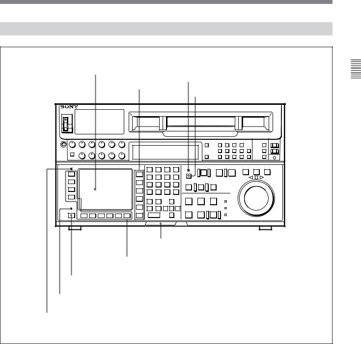
2-1-2 Lower Control Panel (Menu Operations Section)
1Menu display
3MEMORY CARD indicator
2Menu buttons
4ACCESS button
5IC memory card insertion slot
6Function buttons
7ALT button
8MAINTENANCE switch
9ALARM indicator
Lower control panel (menu operations section)
Controls and Parts of Functions and Locations 2 Chapter
Chapter 2 Locations and Functions of Parts and Controls |
2-5 |

Controls and Parts of Functions and Locations 2 Chapter
2-1 Control Panel
1 Menu display
Menus selected by pressing the menu buttons appear here.
Each menu shows the functions assigned to each function button ([F1] to [F10]) and information necessary for making settings, such as time codes.
2 Menu buttons
Press to activate the respective menu.
HOME button: Activates the HOME menu. Settings for basic or editing operations are made in the HOME menu.
TC button: Activates the TC (time code) menu. In the TC menu, you can switch between LTC and VITC and between DF and NDF (DVW-A500/1 and DVW-500/1 only), and make settings for time code displays on an external monitor.
CUE button: Activates the CUE menu. In the CUE menu, you can register 10 cue points per page for a total of 100 cue points.
PF1 button: Activates the PF (Personal Function) 1 menu. In the PF1 menu, you can register frequently used settings in other menus. Settings for video input/output signals are factory set.
PF2 button: Activates the PF (Personal Function) 2 menu. In the PF2 menu, you can register frequently used settings in other menus. Settings for audio input/output signals are factory set.
SET UP button: Activates the SET UP menu. Use the SET UP menu to restore settings to the VTR memory banks or IC memory card, register functions to the PF1/2 menus, and set items in the VTR SETUP menu.
For details, refer to “Chapter 4 Menu Settings” on page 4- 1.
3 MEMORY CARD indicator
Lights up when the IC memory card is inserted.
4 ACCESS button
Press this button to directly activate the MEMORY CARD menu. Flashes when the control panel is accessing the IC memory card.
Note
Do not eject the IC memory card while the ACCESS button lights up as this may damage the contents of the memory card.
5 IC memory card insertion slot
Insert IC memory cards here. VTR settings can be stored on cards and used to configure the VTR and control panel at a later date, thus reducing the time required for set up.
Press the button beside the insertion slot to eject the IC memory card.
6 Function buttons
Activate the functions for the respective function buttons in each menu.
7 ALT (alternative) button
Press to change the functions of the current menu. Press again to return to the original functions.
8 MAINTENANCE switch
Activates the MAINTENANCE menu.
To operate this switch, push it in using the tip of a pen or some other pointed object while holding down the SFT button.
9 ALARM indicator
Lights up when the communication between the VTR and the control panel is abnormal.
2-6 |
Chapter 2 Locations and Functions of Parts and Controls |
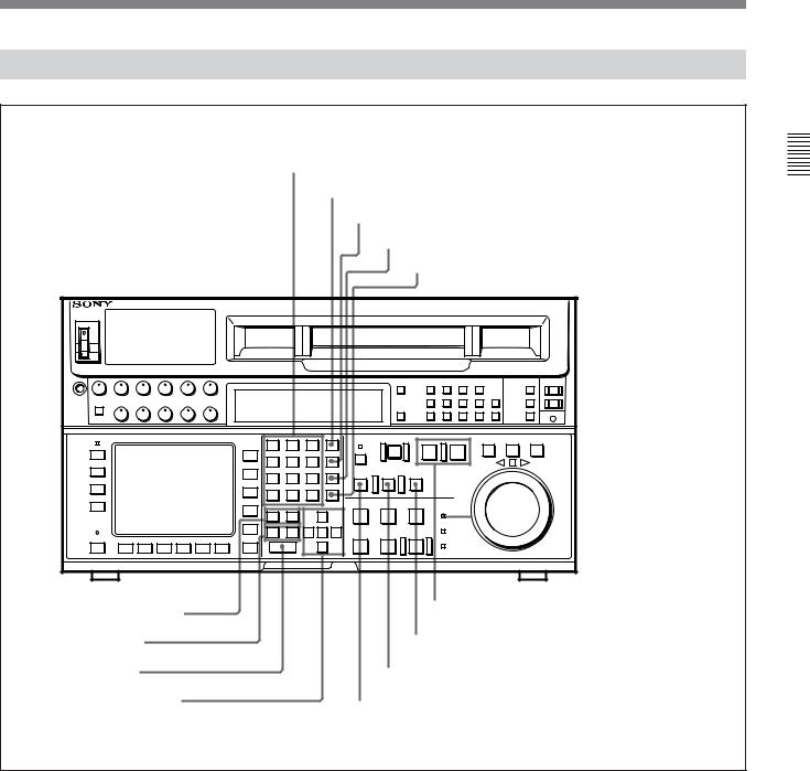
2-1-3 Lower Control Panel (Editing Operations Section)
!ºNumeric buttons and +/– buttons
!¡SFT button
!™RCL button
!£CLR button
!¢SET button
|
@£PREREAD indicator |
!∞AUDIO IN/OUT buttons |
@™PLAYER/RECORDER buttons |
|
!§IN/OUT buttons |
@¡REVIEW button |
!¶ENTRY button |
@ºAUTO EDIT button |
!•Cursor control buttons |
!ªPREVIEW button |
|
Lower control panel (editing operations section)
Controls and Parts of Functions and Locations 2 Chapter
Chapter 2 Locations and Functions of Parts and Controls |
2-7 |

Controls and Parts of Functions and Locations 2 Chapter
2-1 Control Panel
!º Numeric buttons and +/– buttons
Press to input time data or edit points data at the cursor position in menu display. Press buttons 0 to 5 while holding down the SFT button to input A to F (hexadecimal figures) for user bits. Use the +/– buttons to increase or decrease settings.
!¡ SFT (shift) button
Press buttons 0 to 5 while holding down this button to input A to F (hexadecimal figures) for user bits.
Use also in combination with other buttons to perform other operations.
!™ RCL (recall) button
Press to call up a previously entered value.
!£ CLR (clear) button
Press to clear a value.
!¢ SET button
Press to enter a value.
!∞ AUDIO IN/OUT buttons
Press to set AUDIO IN and OUT points during insert mode. Press either AUDIO IN or OUT button while holding down the ENTRY button to set an audio edit point.
!§ IN/OUT buttons
Press to set an IN or OUT point during editing. Press either button while holding down the ENTRY button to set an edit point.
!¶ ENTRY button
Press to enter an edit or cue point.
While holding down this button, press either the AUDIO IN or OUT button, or the IN or OUT button.
!• Cursor control buttons
Press to move the cursor in the menu display. Move the cursor as required to enter a value using the numeric buttons, or to change a menu setting.
!ª PREVIEW button
Press to view the results of an edit on a monitor connected to the recorder VTR without actually recording the edit. During previewing, the tape moves, but actual editing is not carried out. If no IN point has been set when you press this button, the current tape position is set as the IN point at the start of the preview.
@º AUTO EDIT (automatic editing) button
Press to do automatic editing after you have set the edit points. If no IN point has been set when you press this button, the current tape position is set as the IN point at the start of automatic editing.
@¡ REVIEW button
Press to review results of an edit (a section between one IN point and one OUT point) on a monitor connected to the recorder.
@™ PLAYER/RECORDER buttons
Select which VTR is to be controlled by this VTR’s control panel during editing when this VTR is used as a recorder and an external VTR connected to the REMOTE1-IN(9P)/OUT(9P) connectors as a player.
PLAYER: The tape transport buttons and editing operation buttons on the control panel control the external player VTR.
RECORDER: The tape transport buttons and editing operation buttons on the control panel control the recorder VTR (this VTR).
The PLAYER/RECORDER buttons have no effect when using this VTR alone.
@£ PREREAD indicator
Lights up during preread mode.
For details on prereading, refer to “6-2-4 Performing Preread Editing” on page 6-18.
2-8 |
Chapter 2 Locations and Functions of Parts and Controls |
2-1-4 Lower Control Panel (Tape Transport Section)
@¢PREROLL button
@∞EJECT button
@§STANDBY button
@¶EDIT button
@•SERVO indicator |
@ªSTOP button
#ºPLAY button
#¡REC button
#™REC INHIBIT indicator
Lower control panel (tape transport section)
@¢ PREROLL button
Press to position the tape to the preroll point (a position factory set to five seconds before the IN point).
Press this button while holding down the IN, OUT, AUDIO IN or AUDIO OUT button to cue up the tape at the edit point of the respective button.
For details on changing the preroll time, refer to “4-2-8 Setting the Preroll Time (P-ROLL TIME)” on page 4-16.
@∞ EJECT button
Press to eject the cassette. When the button is pressed, the tape is automatically unthreaded and the cassette is ejected in a few seconds. Resets the display when CTL codes appear in the menu display in the lower control panel.
Controls and Parts of Functions and Locations 2 Chapter
Chapter 2 Locations and Functions of Parts and Controls |
2-9 |

Controls and Parts of Functions and Locations 2 Chapter
2-1 Control Panel
@§ STANDBY button
Press this button in other than standby mode to make it light up and place the VTR in standby mode. The head drum rotates in standby mode, thereby shortening the time required for the tape to start.
Press this button while in standby mode to turn the button off and cancel standby mode. The head drum stops rotating and the tape tension is released. If the VTR remains in standby mode for more than eight minutes (factory setting), standby mode is automatically canceled in order to safeguard the tape.
@¶ EDIT button
Press this button while holding down the PLAY button to start manual editing.
Press this button while the VTR is in stop mode to monitor the signal selected in the HOME menu in E-E mode. To cancel E-E mode and stop the tape, press the STOP button.
Hold down this button while the VTR is playing back, searching for an edit point, fast-forwarding or rewinding to monitor the video signal in E-E mode.
@• SERVO indicator
Lights up when the drum servo and capstan servo are locked.
@ª STOP button
Stops the tape (stop mode).
When PB is selected with the ALT button and [F2] (PB/EE) button in the HOME menu, a still picture is output when you press this button. In stop mode, the head drum continues rotating and the tape is wound around the head drum.
When you insert the cassette, the VTR automatically enters stop mode.
The STOP button flashes when the [F2] (OUT REF) button in the PF1 menu is set to input but there is no video input signal, when the [F2] (OUT REF) button in the PF1 menu is set to ref but there is no external reference video signal, or when the input signal is out of phase with the external reference video signal. If you want, you can set 105. REFERENCE SYSTEM ALARM in the VTR SETUP menu so that the STOP button will not flash under the above conditions.
#º PLAY button
Starts playback.
Press this button while holding down the REC button to start recording, or while holding down the EDIT button to start manual editing.
Pressing this button during recording or manual editing changes the VTR to playback mode.
#¡ REC button
Press this button while holding down the PLAY button to start recording.
Hold down this button while the VTR is playing back, searching for an edit point, fast-forwarding or rewinding to monitor the video and audio signals in E- E mode.
Press the STOP button during monitoring to return to the video and audio monitored before you pressed the REC button.
#™ REC INHIBIT indicator
Lights up or goes off, depending on the setting of the ALT button and [F1] (REC INH) button in the HOME menu and the state of the record-protect plug on the cassette.
Status of the REC INHIBIT indicator
Setting of the ALT |
State of the record- |
REC INHIBIT |
and [F1] (REC INH) |
protect plug on the |
indicator |
buttons in the |
cassette |
|
HOME menu |
|
|
all, crash, video, |
Disabled/enabled |
Lit |
audio |
|
|
|
|
|
off |
Disabled |
Lita) |
|
Enabled |
Unlit |
|
|
|
a)By setting 107. REC INHIBIT LAMP FLASHING in the VTR SETUP menu, you can change the setting so that the indicator flashes here.
Recording, editing, and selection of assemble and insert modes are possible only when the indicator is unlit.
2-10 |
Chapter 2 Locations and Functions of Parts and Controls |
2-1-5 Lower Control Panel (Search Operations Section)
#£ VAR button
#¢ JOG button
#∞ SHUTTLE button
#§ Search dial
Lower control panel (search operations section)
#£ VAR button
Press to select variable speed playback mode for noiseless playback in a maximum range of –1 to +3 times normal playback speed, in 54 steps. The playback exceeding this speed range is not possible. In this mode, the VAR button lights up, and the search dial clicks at the positions for still-picture and normal playback speed.
#¢ JOG button
Press to select jog mode. In this mode, the button lights up and playback at –1 to +1 or –3 to +3 times normal playback speed is possible (selectable in the VTR SETUP menu). The playback speed corresponds to the rotational speed of the dial. In this mode, the search dial does not click.
#∞ SHUTTLE button
Press to enter shuttle mode. In this mode, the button lights and playback at –50 to +50 times normal playback speed is possible when using Digital Betacam tape, or at –35 to +35 (DVW-A500/1 only) or –42 to +42 (DVW-A500P/1 only) times normal playback speed when using analog Betacam tape. The playback speed corresponds to the angle of rotation of the dial. In this mode, the search dial clicks at the positions for 0 (still-picture), –10 and +10 times normal playback speed.
Controls and Parts of Functions and Locations 2 Chapter
Chapter 2 Locations and Functions of Parts and Controls |
2-11 |

Controls and Parts of Functions and Locations 2 Chapter
2-1 Control Panel
#§ Search dial
Rotate to search for edit points. Rotate the dial clockwise for forward playback (the z indicator lights up) or counterclockwise for reverse playback (the Z indicator lights up). The p indicator lights up while the VTR is in stop mode.
Press the dial to toggle the VTR between shuttle and jog modes.
Shuttle mode: The playback speed corresponds to the angle of rotation of the dial (–50 to +50 times normal speed when playing back a Digital Betacam tape, and –35 to +35 (DVW-A500/1 only) or –42 to +42 (DVW-A500P/1 only) times normal speed when playing back an analog Betacam tape). The dial clicks at the positions corresponding to 0 (still-picture), –10 and +10 times normal playback speed.
Jog mode: The playback speed, which corresponds to the rotational speed of the dial, ranges from –1 to +1 or –3 to +3 times normal playback speed (selectable in VTR SETUP menu). The dial does not click.
Variable speed playback mode: Noiseless playback at –1 times normal speed when the dial is rotated fully counterclockwise, and +3 times normal speed when rotated clockwise. The dial clicks at the positions of still-picture and normal playback speed.
Capstan override mode: Rotating the dial while holding down the PLAY button changes the playback speed by up to ±15%.
After turning the power on, always set the search dial at the center position (where the p indicator lights up).
2-12 |
Chapter 2 Locations and Functions of Parts and Controls |

2-2 System Set-Up Panel
Lift the lower control panel up to its horizontal position to access the system set-up panel.
Lower control panel |
Accessing the system set-up panel
CONTROL PANEL switch
System set-up panel
CONTROL PANEL switch
Selects which control panel controls this VTR.
INT: Control is by the control panel attached to this VTR.
EXT: Control is by the optional BKDW-514 connected to the CONTROL PANEL connector.
The switch is factory-set to INT.
Controls and Parts of Functions and Locations 2 Chapter
Chapter 2 Locations and Functions of Parts and Controls |
2-13 |
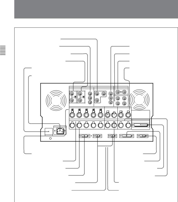
2-23 -Connector3 ConnectorPanel Panel
Controls and Parts of Functions and Locations 2 Chapter
1 COMPOSITE VIDEO OUTPUT
connectors |
|
|
|
|
|
|
||||||||||||||||||||||
2 COMPONENT VIDEO INPUT |
|
|
|
|
|
7 COMPONENT VIDEO |
||||||||||||||||||||||
connectors |
|
|
|
|
|
|
OUTPUT connectors |
|||||||||||||||||||||
3 COMPOSITE VIDEO INPUT connectors |
|
|
|
|
|
8 SERIAL V/A OUTPUT connectors |
||||||||||||||||||||||
and 75Ω termination switch |
|
|
|
|
|
|
|
|
|
|
||||||||||||||||||
|
|
|
|
|
|
|
9 SERIAL V/A INPUT connectors |
|||||||||||||||||||||
4 REF.VIDEO INPUT |
|
connectors and |
|
|
|
|
|
|||||||||||||||||||||
75Ω termination switch |
|
|
|
|
|
|
|
|
|
|
||||||||||||||||||
5BREAKER button |
|
0 AUDIO INPUT (AES/EBU) |
||||||||||||||||||||||||||
|
|
|
|
|
|
|
|
|
|
|
|
|
|
|
|
|
|
|
|
|
|
|
|
|
connectors |
|||
6AC IN connector |
|
|
|
|
|
|
||||||||||||||||||||||
|
|
|
|
|
|
|
|
|
|
|
|
|
|
|
|
|
|
|
|
|
|
|
|
|
|
|
|
|
|
|
|
|
|
|
|
|
|
|
|
|
|
|
|
|
|
|
|
|
|
|
|
|
|
|
|
|
|
|
|
|
|
|
|
|
|
|
|
|
|
|
|
|
|
|
|
|
|
|
|
|
|
|
|
|
|
|
|
|
|
|
|
|
|
|
|
|
|
|
|
|
|
|
|
|
|
|
|
|
|
|
|
|
|
|
|
|
|
|
|
|
|
|
|
|
|
|
|
|
|
|
|
|
|
|
|
|
|
|
|
|
|
|
|
|
|
|
|
|
|
|
|
|
|
|
|
|
|
|
|
|
|
|
|
|
|
|
|
|
|
|
|
|
|
|
|
|
|
|
|
|
|
|
|
|
|
|
|
|
|
|
|
|
|
|
|
|
|
|
|
|
|
|
|
|
|
|
|
|
|
|
|
|
|
|
|
|
|
|
|
|
|
|
|
|
|
|
|
|
|
|
|
|
|
|
|
|
|
|
|
|
|
|
|
|
|
|
|
|
|
|
|
|
|
|
|
|
|
|
|
|
|
|
|
|
|
|
|
|
|
|
|
|
|
|
|
|
|
|
|
|
|
|
|
|
|
|
|
|
|
|
|
|
|
|
|
|
|
|
|
|
|
|
|
|
|
|
|
|
|
|
|
|
|
|
|
|
|
|
|
|
|
|
|
|
|
|
|
|
|
|
|
|
|
|
|
|
|
|
|
|
|
|
|
|
|
|
|
|
|
|
|
|
|
|
|
|
|
|
|
|
|
|
|
|
|
|
|
|
|
|
|
|
|
|
|
|
|
|
|
|
|
|
|
|
|
|
|
|
|
|
|
|
|
|
|
|
|
|
|
|
|
|
|
|
|
|
|
|
|
|
|
|
|
|
|
|
|
|
|
|
|
|
|
|
|
|
|
|
|
|
|
|
|
|
|
|
|
|
|
|
|
|
|
|
|
|
|
|
|
|
|
|
|
|
|
|
|
|
|
|
|
|
|
|
|
|
|
|
|
|
|
|
|
|
|
|
|
|
|
|
|
|
|
|
|
|
|
|
|
|
|
|
|
|
|
|
|
|
|
|
|
|
|
|
|
|
|
|
|
|
|
|
|
|
|
|
|
|
|
|
|
|
|
|
|
|
|
|
|
|
|
|
|
|
|
|
|
|
|
|
|
|
|
|
|
|
|
|
|
|
|
|
|
|
|
|
|
|
|
|
|
|
|
|
|
|
|
|
|
|
|
|
|
|
|
|
|
|
|
|
|
|
|
|
|
|
|
|
|
|
|
|
|
|
|
|
|
|
|
|
|
|
|
|
|
|
|
|
!¡ AUDIO INPUT LEVEL/600Ω |
!¶ VIDEO |
|
|
|
|||||||
CONTROL |
|||||||||||
termination switches |
|
|
|
|
|
||||||
connector |
|
|
|||||||||
!™ ANALOG |
|
|
|
|
|
|
|
||||
AUDIO INPUT |
!• RS-232C connector |
|
|||||||||
connectors |
|
|
|
|
|
|
|
|
|
|
|
!£ ANALOG |
|
|
|
|
|
|
|
||||
AUDIO OUTPUT |
!ª PARALLEL I/O(50P) connector |
||||||||||
connectors |
|
|
|
|
|
|
|
|
|
||
!¢ CONTROL |
|
|
|
@º AUDIO |
|
|
|||||
PANEL connector |
|
|
|
|
|||||||
OUTPUT (AES/EBU) |
|||||||||||
|
|
|
|
|
|
|
|
|
|
|
|
|
|
|
|
|
|
|
connectors |
||||
!∞ REMOTE1 |
|
|
@¡ TIME CODE OUT connector |
||||||||
-IN/OUT(9P) connectors |
|||||||||||
!§ MONITOR |
|
|
@™ TIME CODE IN connector |
||||||||
OUTPUT connectors |
|||||||||||
|
|
|
|
|
|
|
|
|
|
|
|
|
|
|
|
|
|
|
Connector panel |
||||
2-14 |
Chapter 2 Locations and Functions of Parts and Controls |

1COMPOSITE VIDEO OUTPUT connectors (BNC)
Output analog composite video signals. The signal output to connector 3(SUPER) contains superimposed characters for time data or menu settings when on is selected with the ALT button and [F6] (CHARA SUPER) button in the TC menu.
2COMPONENT VIDEO INPUT connectors (BNC)
Accept analog component video signals (Y/R-Y/B-Y).
3COMPOSITE VIDEO INPUT connectors (BNC) and 75Ω termination switch (with optional BKDW-505 for DVW-A500/1 and 500/ 1, or BKDW-506 for DVW-A500P/1 and 500P/1)
Accepts analog composite video signal.
Set the 75Ω termination switch to OFF when this VTR is bridge-connected. Otherwise, set it to ON.
4REF.VIDEO INPUT connectors (BNC) and 75Ω termination switch
One of these connectors accepts a reference video signal. Use a video signal with chroma burst (BVS) or a black and white video signal (VS) as a reference video signal.
When making a bridge connection with a loop-through output, set the 75Ω termination switch to OFF. Otherwise, set it to ON.
5 BREAKER button
Disconnects the primary circuit of the AC power transformer should an excessive current be detected.
6 AC IN connector
Connects to an AC outlet using the power cord supplied with the VTR.
7COMPONENT VIDEO OUTPUT connectors (BNC)
Output analog component video signals (Y/R-Y/B-Y).
8SERIAL V/A (video/audio) OUTPUT connectors (BNC)
Output up to four (1 to 4) serial digital video/audio signal lines. The signal output to connector 4(SUPER) contains superimposed characters for time data or menu settings when on is selected with the ALT button and [F6] (CHARA SUPER) button in the TC menu.
9SERIAL V/A (video/audio) INPUT connectors (BNC)
The left connector accepts serial digital video/audio signals. When the VTR is powered on, the right connector serves as an active loop-through output to allow a bridge connection.
0AUDIO INPUT (AES/EBU) connectors (XLR-3-31)
Accept up to two lines (four channels: channels 1/2 and channels 3/4) of AES/EBU format digital audio signals.
!¡ AUDIO INPUT LEVEL/600Ω termination switches
Set according to the audio input level of each channel input to the ANALOG AUDIO INPUT connectors and the audio input impedance.
LOW with OFF:
Audio input level: –60 dBu (microphone input) Audio input impedance: High (about 20 kΩ )
HIGH with OFF:
Audio input level: +4 dBu (line input) Audio input impedance: High (about 20 kΩ )
HIGH with ON:
Audio input level: +4 dBm (line input) Audio impedance: 600 Ω
!™ ANALOG AUDIO INPUT connectors
(XLR-3-32)
Accept up to five analog audio signal lines (channels 1 to 4 and cue).
!£ ANALOG AUDIO OUTPUT connectors
(XLR-3-31)
Output up to five analog audio signal lines (channels 1 to 4 and cue).
!¢ CONTROL PANEL connector (15-pin)
Connects the control panel through the 15-pin cable supplied with the optional BKDW-510 Control Panel Extension Kit when using the control panel as a remote controller.
Controls and Parts of Functions and Locations 2 Chapter
Chapter 2 Locations and Functions of Parts and Controls |
2-15 |

Controls and Parts of Functions and Locations 2 Chapter
2-3 Connector Panel
!∞ REMOTE1-IN/OUT (9P) connectors
(D-sub 9-pin)
Connect to another DVW-500/1 or 500P/1 VTR or D- 1, D-2, or Betacam VTR through a 9-pin remote control cable. Used when you edit using two VTRs and the BVE-900/910/2000/9000/9100 Editing Control Unit. The REMOTE1-IN and OUT connectors can be used to make a bridge connection.
!§ MONITOR OUTPUT connectors (XLR-3-31)
Output signals for audio monitoring. These connectors output two signal lines: L and R. Select the signals to be output with the MONITOR SELECT buttons and the AUDIO INPUT/MONITOR SELECT buttons on the upper control panel. Through an initial setting, you can enable the adjustment of the volume level with the PHONES level control.
For details, refer to “5-1-2 Selecting Audio Signals”on page 5-2.
!¶ VIDEO CONTROL connector (D-sub 15-pin)
Connects to the optional BVR-50/50P TBC Remote Controller to enable remote control of the internal digital video processor. Before connecting the remote controller, turn off the power to the VTR.
!• RS-232C connector (D-sub 25-pin)
Receives or transmits RS-232C remote control signals and/or VTR status data from/to external equipment. When this connector is being used for communication, the RS-232C indicator on the upper control panel lights up.
!ª PARALLEL I/O(50P) connector (D-sub 50-pin, with optional BKDW-509)
Inputs an external remote control signal.
For details, refer to the Installation Manual.
@º AUDIO OUTPUT (AES/EBU) connectors
(XLR-3-32)
Output a maximum of two lines (four channels: channels 1/2 and 3/4) of AES/EBU format digital audio signals.
@¡ TIME CODE OUT connector (XLR-3-31)
Outputs one of the following time codes according to the VTR operation mode.
In playback mode: Playback time code
In recording mode: Time code generated by the internal time code generator, or time code input to the TIME CODE IN connector.
@™ TIME CODE IN connector (XLR-3-32)
Accepts an external time code for recording to tape. Connect to the time code output connector of the external equipment.
2-16 |
Chapter 2 Locations and Functions of Parts and Controls |

3-1 Connecting External Equipment
3-1-1 Making Digital Connections
The diagram below shows how to connect this VTR to Digital VTR used as a recorder. another DVW-A500/1 series or 500/1 series VTR used
as a player and to a DVR-2100/2100P D-1 Component
DVW-A500/1 or DVW-500/1 series, or BVW-D75 series (player)
SERIAL V/A OUTPUT
Input |
|
BNCcable |
|
|
|
|
|
REMOTE1-IN |
COMPONENT or DVW-A500/1 or DVW-500/1 |
|
|
COMPOSITE |
series VTR |
SERIAL V/A INPUT |
VIDEO OUTPUT |
|
|
9-pinremotecable |
|
|
|
|
|
SERIAL V/A OUTPUT |
cable |
cable |
cable |
|
|
cable |
|
|
BNC |
BNC |
BNC |
REMOTE1-IN |
REMOTE1-OUT |
BNC |
|
|
|
|
|
||
|
|
|
|
|
9-pin remote cable |
|
|
|
|
|
|
REMOTE1 |
SERIAL V/A |
|
|
|
|
|
INPUT |
|
|
|
|
|
|
Output |
|
Video monitor
DVR-2100/2100P (recorder)
Making digital connections
3 Chapter
Up Setting
the VTRChapter3 SettingUp
VTR the
Chapter 3 Setting Up the VTR 3-1
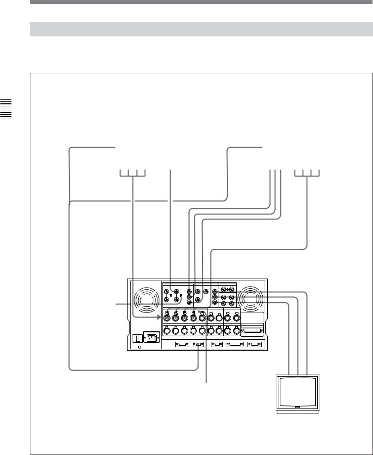
3-1 Connecting External Equipment
3-1-2 Making Analog Connections
The diagram below shows how to make connections for analog video and audio signals from a Betacam/ Betacam SP VTR, 1-inch VTR, or D-2 VTR.
VTR the Up Setting 3 Chapter
REMOTE (9P) |
DVR-28/20 D-2 VTR or |
REMOTE (9P) |
BVW-75/70/65/60 series |
|
BVH-3000 1-inch VTR etc. |
Betacam SP VTR (player) |
|||
|
|
|||
|
(player) |
|
|
|
|
|
|
|
ANALOG AUDIO |
ANALOG VIDEO |
COMPONENT |
AUDIO |
OUTPUT CH-1 to 4 |
OUTPUT |
VIDEO |
OUTPUT CH-1 |
|
|
OUTPUT |
to 4 |
|
|
INPUT |
COMPONENT VIDEO INPUT |
remotepin-9 cable |
|
COMPOSITEVIDEO (withBKDW-505/506) |
|
termination |
COMPONENT or |
||
|
|
|
ANALOG AUDIO INPUT CH-1 to 4 |
|
Set the 75Ω |
|
|
|
switch to OFF |
|
COMPOSITE VIDEO OUTPUT |
|
when making a |
|
|
|
|
|
|
|
bridge |
|
|
|
connection for |
|
|
|
an analog |
|
|
|
composite video |
|
|
|
signal. |
|
|
|
Otherwise, set it |
|
cableBNC cableBNC cableBNC |
|
to ON. |
|
|
|
|
|
Set the analog audio input level and impedance |
|
|
using the AUDIO INPUT LEVEL/600Ω termination |
|
|
switches as follows: |
|
|
For line input with a 600Ω termination: HIGH with |
|
|
ON |
|
|
For high-impedance line input: HIGH with OFF |
Video monitor |
|
For high-impedance microphone input: LOW with |
||
|
||
OFF |
|
Making analog connections
3-2 Chapter 3 Setting Up the VTR
 Loading...