


C-455-100-12(1)
Color Video Camera
Operating Instructions
Software Version 2.00
Before operating the unit, please read this manual thoroughly and retain it for future reference.
BRC-X1000/H800
© 2016 Sony Corporation

Table of Contents |
|
Overview |
|
Using This Manual ................................................ |
4 |
Precautions for Preventing Access to the Camera |
|
by an Unintended Third Party ............................ |
5 |
Features .................................................................. |
6 |
Location and Function of Parts ........................... |
7 |
Camera ............................................................ |
7 |
Remote commander (supplied) ..................... |
10 |
System Configuration ......................................... |
13 |
Operating the camera using the supplied remote |
|
commander ................................................... |
13 |
Operating the camera using the remote |
|
controller (not supplied) ............................... |
13 |
Connecting multiple cameras to the remote |
|
controller (not supplied) ............................... |
14 |
How to Use Menus ............................................... |
30 |
Using the supplied remote commander ......... |
30 |
EXPOSURE Menu .............................................. |
31 |
COLOR Menu ..................................................... |
33 |
DETAIL Menu ..................................................... |
34 |
KNEE Menu ......................................................... |
35 |
GAMMA/VISIBILITY ENHANCER Menu .... |
36 |
GAMMA ....................................................... |
36 |
VISIBILITY ENHANCER ........................... |
36 |
FOCUS Menu ...................................................... |
37 |
PICTURE/OPTICAL FILTER Menu ............... |
37 |
PAN TILT/ZOOM Menu .................................... |
38 |
VIDEO OUT Menu ............................................. |
40 |
SYSTEM Menu .................................................... |
40 |
NETWORK Menu ............................................... |
41 |
PICTURE PROFILE Menu ............................... |
42 |
PTZ TRACE Menu ............................................. |
43 |
Recording pan/tilt and zoom operations ....... |
43 |
Playing pan/tilt and zoom operations ............ |
43 |
Deleting recorded pan/tilt and zoom |
|
operations ...................................................... |
44 |
Installation and Connection |
|
Installing the Camera ......................................... |
15 |
Installing the camera on a desk ..................... |
15 |
Installing the camera at a high spot .............. |
16 |
Connecting the Camera ...................................... |
23 |
Connecting an AC power supply .................. |
23 |
Connecting the camera to a PoE+ (Power over |
|
Ethernet Plus) power supply device .............. |
23 |
Connecting a single camera to a switcher, |
|
recorder and monitor .................................... |
24 |
Connecting a single camera to a single remote |
|
controller (not supplied) ............................... |
25 |
Connecting a single camera to a single remote |
|
controller (not supplied) ............................... |
25 |
Connecting multiple cameras to a single remote |
|
controller (not supplied) ............................... |
26 |
Connecting a commercially available video |
|
switcher ......................................................... |
26 |
Externally synchronizing a single camera .... |
28 |
Adjusting and Configuring through On-Screen Menus
About On-Screen Menus .................................... |
29 |
Confirming selection of menu items and settings |
|
/ Executing operations .................................. |
29 |
Main menu .................................................... |
29 |
Setting menu ................................................. |
29 |
Operations Using the Supplied |
|
Remote Commander |
|
Before Starting Operations ................................. |
45 |
Turning on the Power .......................................... |
45 |
Pan/Tilt and Zoom Operations ........................... |
45 |
Panning and tilting ........................................ |
45 |
Zooming ........................................................ |
46 |
Operating multiple cameras with the remote |
|
commander .................................................... |
46 |
Adjusting the Camera ......................................... |
47 |
Focusing on a subject .................................... |
47 |
Shooting with back lighting .......................... |
47 |
Storing the Camera Settings in Memory |
|
– Preset Feature ................................................... |
48 |
Storing the camera status .............................. |
48 |
Recalling stored status .................................. |
48 |
Clearing the preset memory .......................... |
48 |
Storing Camera Pan/Tilt and Zoom Operations |
|
– PTZ TRACE function ...................................... |
49 |
Recording pan/tilt and zoom operations ....... |
49 |
Playing pan/tilt and zoom operations ............ |
49 |
Deleting recorded pan/tilt and zoom |
|
operations ...................................................... |
49 |
Accessing from a Web Browser |
|
Before starting the operation .............................. |
50 |
Setting-up the PC .......................................... |
50 |
2

Accessing the camera from a web browser .. 50 |
|
Operation ............................................................. |
51 |
Connecting with RCP/MSU devices ............ |
51 |
Upgrading the firmware ................................ |
51 |
Changing the password ................................. |
51 |
Appendix |
|
Message List ........................................................ |
53 |
Troubleshooting ................................................... |
54 |
Menu Configuration ........................................... |
55 |
Preset Items ......................................................... |
58 |
Specifications ....................................................... |
60 |
Dimensions ................................................... |
62 |
SYSTEM SELECT switch settings .............. |
63 |
Pin array of the VISCA RS-422 terminal and |
|
how to use it .................................................. |
63 |
3

Overview
Safety Regulations (Supplied)
Describes the important points for safe use of the camera.
Be sure to read it.
Operating Instructions (This document/ Web)
These operating instructions describe the names of the various parts of camera and installation, connection, and operation methods.
Using This Manual
The Operating Instructions is designed to be read on a computer display.
The content you need to know in order to use the camera is described here.
Read it before you operate the camera.
Jumping to a related page
When you read the instructions on a computer display and click on the related part of the relevant page that is being displayed, you jump to the related page. Relevant pages can be searched easily.
Software display examples
The software displays described in this manual are explanatory examples. Note that some displays may be different from the ones that actually appear.
The illustrations of the camera and menu display in the instructions show the BRC-X1000 as an example. Only supported functions are displayed.
Printing the Operating Instructions
Depending on your system, certain displays or illustrations in the Operating Instructions, when printed out, may differ from those that appear on your screen.
NOTICE TO USERS
© 2016 Sony Corporation. All rights reserved. This manual or the software described herein, in whole or in part, may not be reproduced, translated or reduced to any machine readable form without prior written approval from Sony Corporation.
SONY CORPORATION PROVIDES NO WARRANTY WITH REGARD TO THIS MANUAL, THE SOFTWARE OR OTHER INFORMATION CONTAINED HEREIN AND HEREBY EXPRESSLY DISCLAIMS ANY IMPLIED WARRANTIES OF MERCHANTABILITY OR FITNESS FOR ANY PARTICULAR PURPOSE WITH REGARD TO THIS MANUAL, THE SOFTWARE OR SUCH OTHER INFORMATION. IN NO EVENT SHALL SONY CORPORATION BE LIABLE FOR ANY INCIDENTAL, CONSEQUENTIAL OR SPECIAL DAMAGES, WHETHER BASED ON TORT, CONTRACT, OR OTHERWISE, ARISING OUT OF OR IN CONNECTION WITH THIS MANUAL, THE SOFTWARE OR OTHER INFORMATION CONTAINED HEREIN OR THE USE THEREOF.
Sony Corporation reserves the right to make any modification to this manual or the information contained herein at any time without notice.
The software described herein may also be governed by the terms of a separate user license agreement.
• is a trademark of Sony Corporation.
•“Exmor R” and 


 are trademarks of Sony Corporation.
•HDMI, HDMI High-Definition Multimedia Interface, and HDMI logo is a trademark of HDMI Licensing LLC and is registered trademark in United States and/or other countries.
•Microsoft, Windows, and Internet Explorer are registered trademarks of United States Microsoft Corporation in the United States and/or other countries.
•JavaScript is a trademark or registered trademark of Oracle Corporation, its affiliates or subsidiaries in the United States and other countries.
•Adobe, Adobe Reader and Adobe Flash are trademarks of Adobe Systems Incorporated.
Other system names, product names appearing in this document are trademarks or registered trademarks of their respective manufacturers. Trademarked items are not indicated by ® or ™ symbols in this document.
4

Precautions for Preventing Access to the Camera by an Unintended Third Party
The camera settings may be changed by an unintended third party on the network, depending on the usage environment.
The camera can be fraudulently accessed in a network environment where a device is connected or connectable to the network without the administrator’s permission, or where a PC or other network device connected to the network can be used without any permission.
After configuring the camera, immediately change the password you use for upgrading the firmware on the camera, from a Web browser on your PC, and for changing settings. For how to change password, see “Changing the password” (page 51).
5

Features
Pan/Tilt/Zoom CMOS video camera equipped with a small built-in pan-tilt head
•The camera unit is equipped with a 1.0-type Exmor R→ CMOS sensor and an optical 12× zoom lens with pan/tilt/zoom features integrated into a small built-in pan-tilt head. This versatile camera can be used for various applications.
•The pan-tilt head can pan to the right or left by ±170 degrees and tilt upward to 90 degrees and downward to 30 degrees, which allows the camera to remotely shoot wide areas.
•The camera pans and tilts smoothly, even at low movement speed.
•The camera pans and tilts quietly, even at its maximum speed of 60 degrees per second.
•Up to 100 preset positions can be saved. The PTZ Motion Sync function enables smooth preset operation with coordinated pan/ tilt and zoom. In addition, the speed of movement between positions can be adjusted from an optional RM-IP500/IP10 Remote Controller.
Zoom performance for capturing distant subjects
In addition to 12× optical zoom, it uses Sony’s 2×*1 Clear Image Zoom function and 2× Tele Convert mode*2 to achieve the equivalent of up to 48×*2 telephoto performance.
*1 When shooting at 1920×1080 only. 1.5× when shooting at 3840×2160.
*2 When shooting at 1920×1080 only.
High sensitivity and high resolution from built-in 1.0-type CMOS image sensor
With the built-in highly photosensitive 1.0-type Exmor R→ CMOS sensor, high resolution shooting with less noise can be achieved. Highly sensitive shooting unique to the large sensor can be achieved. In addition, the camera is equipped with a ZEISS Vario-Sonnar T* builtin lens.
Multi-format support
3840×2160/29.97p (2SI) *1 1920×1080/59.94p, 1920×1080/59.94i, 1280×720/59.94p
3840×2160/25p (2SI) *1
1920×1080/50p, 1920×1080/50i, 1280×720/50p 3840×2160/23.98p(2SI)*1, 1920×1080/23.98p Switching possible with the SYSTEM SELECT switch *1 Compatible only with the BRC-X1000
Equipped with 3G-SDI and HDMI output
The camera can deliver 4K output for both Dual Link 3G-SDI×2 (2SI) and HDMI.
Various installation environments are available in order to establish a connection with HDMI, in addition to the coaxial cable.
Equipped with PoE+ (Power Over Ethernet Plus)
The camera is compatible with PoE+ (Power Over Ethernet Plus), so a single LAN cable can be used for power provision and control.
Compatible with VISCA over IP protocol
An IP connection can be established between the camera and the remote controller.
Equipped with External Video Sync Function
The camera is equipped with an external video sync function to synchronize the camera images on multiple cameras.
Equipped with Tally Lamp Function
The camera is equipped with a Tally lamp that quickly distinguishes when the camera is in use.
The front Tally lamp is a large Tally lamp used for improving visibility. The camera is also equipped with a Tally lamp behind the camera block, in order to improve visibility from the rear side.
Supports network connection with RCP/ MSU
Network connection to an optional remote control panel (RCP) or master setup unit (MSU) is supported.
Picture Profile preset function
Picture Profile presets PP1 to PP6 can be loaded. By using these presets, you can match the image texture with other types of camcorders that support the Picture Profile function, or create an image texture that is similar to that of cinematic film.
Built-in ND filter
The camera is equipped with a built-in ND filter to enable adjustment of the light level in bright lighting conditions without changing the shutter speed or iris. You can choose from Off, 1/4, 1/16, and 1/64.
6
Location and Function
of Parts
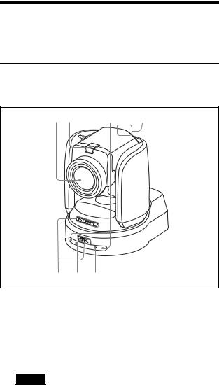
Camera
Front (BRC-X1000)
1 2 |
3 |
4 |
|
|
|
|
|
5 6 7
ALens
This is a 12× magnification optical zoom lens. When CLEAR IMAGE ZOOM in the PAN TILT ZOOM menu is turned on, the camera can zoom up to 18× for 4K and 24× for HD.
Note
Do not touch the part around the lens when energized.
BTally lamp
Lights up in red when a VISCA Tally command is received or the camera is selected by the remote controller (not supplied) (depending on the setting mode). Brightness can be selected from HIGH, LOW, and OFF (the lights are turned off) in TALLY MODE in the SYSTEM menu.
CRemote commander sensors
These are sensors for the supplied remote commander.
DBack Tally lamp
Lights up in red when a VISCA Tally command is received or the camera is selected by the remote controller (not supplied) (depending on the setting mode). The back Tally lamp does not light up when TALLY MODE in the SYSTEM menu (page 41) is set to OFF.
If a fault inside the camera is detected, the lamp flashes at approximately 0.7 second intervals irrespective of the on/off status of the back Tally lamp. When a fault is detected, its content will be displayed in the menu (see page 53). If, however, “CAMERA FAULT” is shown, the back Tally lamp may not flash.
ESONY nameplate, 4K or HD nameplate
Pull them out to turn them over and attach upside down if required.
4K: BRC-X1000 HD: BRC-H800
FPOWER lamp
Flashes in green when the camera is connected to an outlet using an AC adapter and power cord (not supplied), or when power is being supplied by connecting the camera and PoE+ Hub using a LAN cable. The green lamp stops flashing and lights up when start-up is complete.
The green lamp flashes when the camera receives an operation command from the supplied remote commander.
The orange lamp comes on when the POWER button on the supplied remote commander is pressed.
The yellow lamp flashes while upgrading the firmware.
The orange lamp flashes when there are defects in the camera (for instance, when rotations of fan motor slow down or stop etc.).
GNetwork lamp
Lamp flashes during initialization when it is connected to a PoE+ Hub using a LAN cable and power is being supplied from the PoE+ Hub. The lamp lights up when it is connected to the network once start-up is complete.
Lights up after start-up is complete if network is connected, when power is supplied to the camera from outlet using AC adapter and power cord. The lamp is unlit when not connected to the network. The lamp turns off while upgrading the firmware. The lamp flashes when there are defects in the camera (for example, when the fan motor stops).
7

Back |
|
|
|
|
|
|
|
|
|
|
|
|
|
|
|
|
|
|
|
BRC-X1000 |
|
|
|
|
|
|
|
|
|
|
|
|
|
|
|
|
|
||
8 |
9 |
0 |
|
qa |
qs |
|
qd |
|
|
qf |
|
|
|||||||
|
|
|
|
|
IR SELECT |
|
CAMERA SETUP |
|
|
|
|||||||||
|
|
|
|
|
1 |
2 |
3 |
|
|
|
|
|
|
|
|
|
|
|
|
|
|
|
|
|
|
|
|
|
1 |
2 |
3 |
4 |
5 |
6 |
7 |
8 |
|
|
|
|
SYSTEM |
|
IN |
VISCA RS - 422 |
OUT |
|
|
|
|
LAN |
|
12V |
|
|
|
||||
|
|
|
|
|
|
|
|
|
|
|
|||||||||
|
SELECT |
|
|
|
|
|
|
OSD |
|
|
|
|
|
|
|
|
|
|
|
|
|
|
|
|
|
|
|
|
|
|
|
|
|
|
|
|
|
||
|
|
|
|
|
|
|
|
ON |
OFF |
|
|
|
|
|
|
|
|
|
|
|
HDMI OUT |
|
MONITOR OUT |
LINE OUT |
|
|
|
|
EXT SYNC IN |
|
|
|
|||||||
|
|
|
|
SDI 1 |
|
|
SDI 2 |
SDI 1 |
SDI 2 |
|
|
TERMI- |
|
|
|||||
|
|
|
|
|
|
|
|
|
|
|
|
||||||||
|
|
|
|
|
|
|
|
|
|
|
|
|
|
|
|
|
|
|
|
|
|
|
|
|
|
|
|
|
|
|
|
|
|
|
|
|
NATION |
|
|
|
|
|
|
|
|
|
|
|
|
|
|
|
|
|
|
|
ON OFF |
|
|
qg |
qh |
|
qj |
qk |
ql |
w; |
|
|
|
|
|
wa |
ws |
wd |
wf |
||||
BRC-H800 |
|
|
|
|
|
|
|
|
|
|
|
|
|
|
|
|
|
|
|
8 |
9 |
0 |
qa |
qs |
|
qd |
|
qf |
|
|
|||||||||
|
|
|
|
|
IR SELECT |
|
CAMERA SETUP |
|
|
|
|||||||||
|
|
|
|
|
1 |
2 |
3 |
|
|
|
|
|
|
|
|
|
|
|
|
|
|
|
|
|
|
|
|
|
1 |
2 |
3 |
4 |
5 |
6 |
7 |
8 |
|
|
|
|
SYSTEM |
|
IN |
VISCA RS - 422 |
OUT |
|
|
|
|
|
LAN |
12V |
|
|
|
||||
|
|
|
|
|
|
|
|
|
|
|
|||||||||
|
SELECT |
|
|
|
|
|
|
OSD |
|
|
|
|
|
|
|
|
|
|
|
|
|
|
|
|
|
|
|
|
|
|
|
|
|
|
|
|
|
||
|
|
|
|
|
|
|
|
ON |
OFF |
|
|
|
|
|
|
|
|
|
|
|
HDMI OUT |
|
MONITOR |
|
|
LINE OUT |
|
|
|
|
|
|
EXT SYNC IN |
|
|
|
|||
|
|
|
|
OUT |
|
|
|
|
|
|
|
|
TERMI- |
|
|
||||
|
|
|
|
|
|
|
|
|
|
|
|
|
|
|
|
|
|||
|
|
|
|
|
|
|
|
|
|
|
|
|
|
|
|
|
NATION |
|
|
|
|
|
|
|
|
|
|
|
|
|
|
|
|
|
|
|
ON OFF |
|
|
qg |
qh |
|
qj |
qk |
ql |
w; |
|
|
|
wa |
ws |
wd |
wf |
||||||
HSYSTEM SELECT switch
Used for selecting the video format of the signal to be output from the HDMI OUT, MONITOR OUT, and LINE OUT terminals.
For details, see “SYSTEM SELECT switch settings” (page 63).
IAC adapter cord clamper
Fix the cord of an AC adapter with the cord clamper so that it does not come out.
JIR SELECT switch
Select the camera number when you operate multiple cameras with the same remote commander.
K  Remote commander sensors
These are sensors for the supplied remote commander.
LNetwork reset switch
This switch is for initializing network settings such as the IP address.
Press the switch for 5 seconds or longer with a pen point, etc., to initialize the network settings.
The camera will reboot, and the network settings will return to the factory default.
Factory settings for network
IP address: 192.168.0.100 Subnet mask: 255.255.255.0 Default gateway: 0.0.0.0 Name: CAM1
User name: admin* Password: Admin_1234
* The user name cannot be changed.
MCAMERA SETUP switches SDI format/level settings
The baud rate settings and camera address settings of RS-422 are set for VISCA communication.
CAMERA SETUP switch settings
|
|
|
|
|
|
|
|
|
|
|
|
|
|
|
|
|
|
|
|
|
|
|
|
|
|
|
|
|
|
|
|
|
|
|
|
|
|
|
|
|
|
|
|
|
|
|
|
|
|
|
|
|
|
|
|
|
|
|
|
|
|
|
|
|
|
|
|
|
|
|
|
|
|
|
|
|
|
|
|
|
|
|
|
|
|
|
|
|
|
|
|
|
|
|
|
|
|
|
|
|
|
1 |
|
4 5 6 7 |
|
|
|
|
||||||||||||||||
|
|
|
|
|
|
|
|
|
|
|
|
|
|
|
|
|
|
|
|
|
|
|
|
|
Switch No. |
|
|
|
|
|
|
|
|
|
|
Setting items |
|||||||||||||
|
|
|
|
|
|
|
|
|
|
|
|
|
|
|
|
|
|
|
|
|
|
|
|
|
1 |
|
Setting up 3G-SDI level |
||||||||||||||||||||||
|
|
|
|
|
|
|
|
|
|
|
|
|
|
|
|
|
|
|
|
|
|
|
|
|
2 |
|
System reserve |
||||||||||||||||||||||
|
|
|
|
|
|
|
|
|
|
|
|
|
|
|
|
|
|
|
|
|
|
|
|
|
3 |
|
|
|
|
|
|
|
|
|
|
|
|
|
|
|
|
|
|
|
|
|
|
|
|
|
|
|
|
|
|
|
|
|
|
|
|
|
|
|
|
|
|
|
|
|
|
|
|
|
4 |
|
Baud Rate settings of RS-422 for VISCA |
||||||||||||||||||||||
|
|
communication |
||||||||||||||||||||||
|
|
|
|
|
|
|
|
|
|
|
|
|
|
|
|
|
|
|
|
|
|
|
|
|
5 |
|
VISCA Address settings for VISCA |
||||||||||||||||||||||
|
|
communication |
||||||||||||||||||||||
6 |
|
|||||||||||||||||||||||
|
|
|
|
|
|
|
|
|
|
|
|
|
|
|
|
|
|
|
|
|
|
|
|
|
|
|
|
|
|
|
|
|
|
|
|
|
|
|
|
|
|
|
|
|
|
|
|
|
|
7 |
|
|
|
|
|
|
|
|
|
|
|
|
|
|
|
|
|
|
|
|
|
|
|
|
|
|
|
|
|
|
|
|
|
|
|
|
|
|
|
|
|
|
|
|
|
|
|
|
|
8 |
|
System reserve |
||||||||||||||||||||||
|
|
|
|
|
|
|
|
|
|
|
|
|
|
|
|
|
|
|
|
|
|
|
|
|
1SDI format/level settings
This setting is enabled when the signal format is 1920×1080/50p or 1920×1080/59.94p.
Switch state |
SDI format/level |
ON Level-B
OFF Level-A
*Turn the power off or to standby, then turn the power on to reflect the changes after setting.
4 Baud Rate settings of RS-422 for VISCA communication
Switch state |
Baud Rate |
|
|
ON |
38400 bps |
|
|
OFF |
9600 bps |
|
|
* Turn the power off and on to reflect the changes after setting.
567 Camera address settings Sets camera address.
8

It is normally set to “Auto”. When “Auto” is selected, an address is automatically assigned to the camera.
To set the address manually, set a value between “1” to “7” for this switch as indicated below.
|
Switch No. |
|
Camera address |
|
|
|
|
|
|
5 |
6 |
|
7 |
|
|
|
|||
|
|
|
|
|
OFF |
OFF |
|
OFF |
Auto |
|
|
|
|
|
ON |
OFF |
|
OFF |
1 |
|
|
|
|
|
OFF |
ON |
|
OFF |
2 |
|
|
|
|
|
ON |
ON |
|
OFF |
3 |
|
|
|
|
|
OFF |
OFF |
|
ON |
4 |
|
|
|
|
|
ON |
OFF |
|
ON |
5 |
|
|
|
|
|
OFF |
ON |
|
ON |
6 |
|
|
|
|
|
ON |
ON |
|
ON |
7 |
|
|
|
|
|
*Turn the power off and on to reflect the changes after setting.
N U (earth) terminal
OHDMI OUT terminal
Supplies the images as an HDMI video signal.
*The contents of the menu screen, such as text, can be displayed in the output signal when the OSD switch is turned ON.
Notes
•When either 0 or 8 is selected for SYSTEM SELECT, 2K output from the HDMI output terminal results in lower quality images.
•When 7 is selected for SYSTEM SELECT, VGA output from the HDMI output terminal results in lower quality images.
PVISCA RS-422 IN terminal
Connect with an remote controller (not supplied). When you connect multiple cameras, connect it to the VISCA RS-422 OUT terminal of the previous camera in the daisy chain connection.
QVISCA RS-422 OUT terminal
When you connect multiple cameras, connect it to the VISCA RS-422 IN terminal of the next camera in the daisy chain connection.
RMONITOR OUT
Outputs the image from the camera as a 4K or HD signal.
4K output:
Connect the SDI 1 (3G-SDI) output to the SDI 1 input and the SDI 2 (3G-SDI) output to the SDI 2 input respectively.
HD output:
Connect to SDI 1 (3G-SDI) or SDI 2 (3G-SDI).
*The contents of the menu screen, such as text, can be displayed in the output signal when the OSD switch is turned ON.
*For the BRC-H800, only HD output is available.
SOSD (On Screen Display) switch
The contents of the menu screen, such as text, can be superimposed onto the video signal output to MONITOR OUT & HDMI OUT when the switch is turned ON.
TLINE OUT
Outputs the image from the camera as a 4K or HD signal. OSD (screen display) is not superimposed, irrespective of the OSD switch setting.
4K output:
Connect the SDI 1 (3G-SDI) output to the SDI 1 input and the SDI 2 (3G-SDI) output to the SDI 2 input respectively.
HD output:
Connect to SDI 1 (3G-SDI) or SDI 2 (3G-SDI).
*For the BRC-H800, only HD output is available.
U LAN (network) terminal (RJ-45)
Network communication and PoE+* power supply are provided using the network cable (category 5e or higher, shielded twist pair).
For more information on the connection, refer to the
instruction manual of the power supply system. (*PoE+: an abbreviation of Power over Ethernet Plus, which complies with IEEE802.3at)
The indicator lights up or flashes when the camera is connected to the network. The indicator is off when the camera is not connected to the network.
VEXT SYNC IN
Accepts an external sync signal.
W TERMINATION switch
X 12 V !(DC power input) terminal
Connect the AC adapter (not supplied).
Note
Do not use any AC adapter other than the recommended model (sold separately). Otherwise, a fire or malfunction may occur.
9
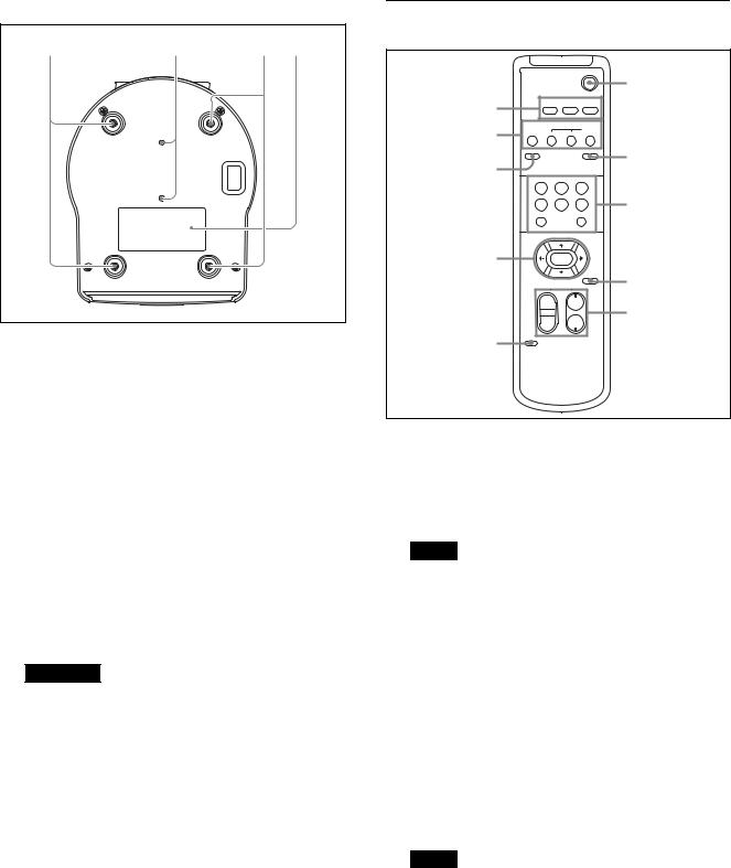
Bottom
wg |
wh |
wg wj |
YCeiling bracket mounting screw holes
When you install the camera to the ceiling, on a shelf, or in another high spot, secure the supplied ceiling bracket to these holes using four of the supplied screws.
The four feet are attached to the holes at the factory.
For installation, see “Installing the camera at a high spot” (page 16).
ZTripod screw holes (1/4-20UNC)
Used to fix the camera to the camera tripod or something similar.
wj Rating label
This label shows the name of device and its electric rating.
Important
The product name and electric rating are located at the bottom of the unit.
Remote commander (supplied)
|
|
|
POWER |
|
|
|
|
|
6 |
1 |
CAMERA SELECT |
|
||
1 |
2 |
3 |
|
|
|
FOCUS |
|
|
|
2 |
AUTO |
|
MANUAL |
|
FAR |
NEAR |
|
||
|
DATA SCREEN |
|
BACK LIGHT |
7 |
3 |
|
|
|
|
|
|
|
|
|
|
STD |
REV |
|
|
|
1 |
2 |
3 |
|
|
4 |
5 |
6 |
8 |
|
PRESET |
|
RESET |
|
|
POSITION |
|
|
|
|
PAN-TILT |
|
|
|
4 |
HOME |
|
|
|
|
|
|
PAN-TILT |
|
|
|
|
RESET |
9 |
|
SLOW ZOOM FAST |
|||
|
|
|||
|
T |
|
T |
q; |
|
W |
W |
||
|
|
|||
L/R
DIRECTION SET
5
ACAMERA SELECT buttons
Press the button corresponding to the camera you want to operate with the remote commander. The camera number can be set using the IR SELECT switch on the rear of the camera.
Note
If two or more cameras are adjacent and have the same camera number, they are operated simultaneously with the supplied remote commander. When you install the cameras close to each other, set different camera numbers.
For setting of camera No., see “Operating multiple cameras with the remote commander” (page 46).
BFOCUS buttons
Used for focus adjustment.
Press the AUTO button to adjust the focus automatically. To adjust the focus manually, press the MANUAL button, and adjust it with the FAR and NEAR buttons.
Note
Press the MANUAL button and adjust the focus manually when shooting the following objects.
•White walls and other objects without contrast
•Objects behind glass
•Objects with horizontal stripes
•Objects on which bright lights are cast or reflected
•Nightscapes and other dark objects with blinking lights
10
•Lit objects shot with darkened exposure adjustment or exposure compensation settings
CDATA SCREEN button
Press this button to display the main menu PAGE. Press it again to close the menu. If you press the button when a lower-level menu is selected, the display goes back to a higher-level menu.
Notes
•You cannot perform pan/tilt/zoom operations while the menu is displayed, except when recording using the PTZ TRACE function.
•The menus are output through MONITOR OUT and HDMI OUT. When you want to display the menus, turn on the OSD switch on the back of the camera.
DPAN-TILT button
Press the arrow buttons to pan or tilt the camera. Press the HOME button to face the camera back to the front.
When the menu is displayed, use V or v to select the menu items and B or b to change the set values. Display the menu of selected items with the HOME button.
The selected setting menu is displayed by pressing the HOME button when the main menu is displayed.
EL/R DIRECTION SET button
Hold down this button and press the REV button to change the direction of the camera movement to be opposite the direction of the arrows on the B and b buttons. To reset the direction of the camera movement, press the STD button while holding down this button.
FPOWER button
Press this button to turn on power or to put the camera in the standby mode.
GBACK LIGHT button
Press this button to enable backlight compensation. Press it again to disable backlight compensation.
Note
The BACK LIGHT button is enabled when MODE in the EXPOSURE menu is FULL AUTO, SHUTTER Pri, IRIS Pri, or GAIN Pri.
HPOSITION buttons
Hold down the PRESET button and press button 1 to 6 to store the current camera direction, zoom, focus adjustment and backlight compensation in the memory of the pressed number button.
To erase the memory contents, hold down the RESET button and press button 1 to 6.
Notes
•These buttons do not function when the menu is displayed.
•Some memory contents may not be erased even if you use the RESET button.
For details on items that can be stored by the PRESET button and erased by the RESET button, see “Preset Items” (page 58).
IPAN-TILT RESET button
Press this button to reset the pan/tilt position.
JZOOM buttons
Use the SLOW button to zoom slowly, and the FAST button to zoom quickly.
Press the T (telephoto) side of the button to zoom in, and the W (wide angle) side to zoom out.
11
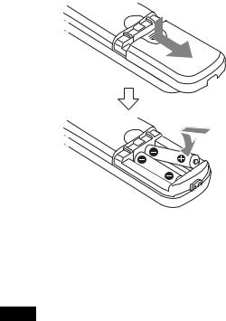
Installing Batteries in the remote commander
Two R6 (size AA) batteries (not supplied)
Installing batteries
Two R6 (size AA) batteries are required for the remote commander. To avoid the risk of explosion, use R6 (size AA) manganese or alkaline batteries.
Note
Danger of explosion if the batteries are incorrectly replaced. Replace only with the same or equivalent type recommended by the manufacturer. When you dispose of the batteries, you must obey the laws of your area or country.
R6 (size AA) batteries are not supplied.
12
System Configuration
This camera can be arranged into various system configurations with other products (not supplied). This section describes typical system examples, with the required components and the main usage of each system.
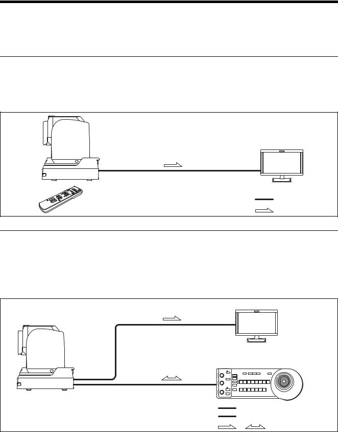
Operating the camera using the supplied remote commander
What you can do with this system
Operate the camera readily from a short distance.
System Configuration
|
Video monitor |
|
Video signal |
Remote commander (supplied) |
Signal flow |
|
Operating the camera using the remote controller (not supplied)
What you can do with this system
Perform pan/tilt and zoom operations using the joystick of the remote controller.
System Configuration
|
Video monitor |
Remote controller |
|
|
Video signal |
|
Remote Control (VISCA) signal |
, |
Signal flow |
13

Connecting multiple cameras to the remote controller (not supplied)
What you can do with this system
•Operate up to seven cameras remotely using a single remote controller.
•Perform pan/tilt and zoom operations using the joystick.
System Configuration
|
Video monitor |
|
Video switcher |
Remote controller |
|
Video signal |
|
Remote Control (VISCA) signal |
|
Tally/contact signal |
|
, |
Signal flow |
14
Installation and Connection
Installing the Camera
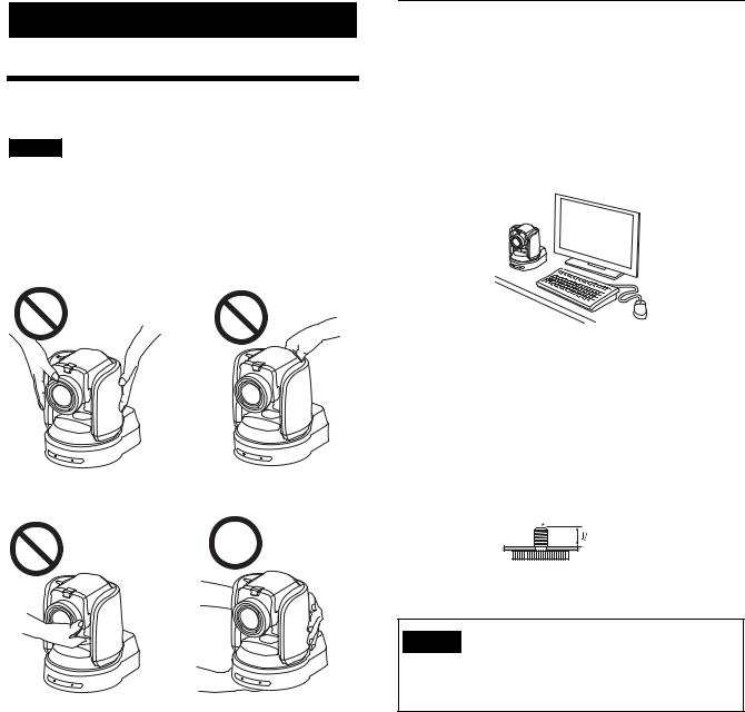
Notes
•Be sure to provide safety measures against falling when you mount the camera.
•Do not grasp the camera head when carrying the camera.
•Do not turn the camera head by hand. Doing so may result in a camera malfunction.
Installing the camera on a desk
Installing the camera on a desk
Place the camera on a flat surface.
If you have to place the camera on an inclined surface, make sure that the inclination is less than ±15 degrees to guarantee pan/tilt performance, and take measures to prevent it from falling.
Attaching the camera to a tripod
Screw the tripod screw into a tripod screw hole on the bottom of the camera.
The tripod should be placed on a level surface, and tighten the screw firmly by hand.
The tripod screw should be compliant with the following standards.
 1/4 -20UNC
4= 4.5 mm to 7 mm
4= 0.18 to 0.27 inches
Caution
Installation of the camera using the tripod screws and screw holes should not be done for installation on a ceiling, shelf, or other high spot.
15
Installing the camera at a high spot
The camera can be mounted on a ceiling or on a shelf or stand located at a high spot using the supplied ceiling bracket.
The surface on which the camera will be mounted should be level. If you have to mount the camera on a tilted surface, make sure that the angle is less than 15 degrees to ensure the camera can pan/tilt properly.
Caution
•When you want the camera to be mounted at a high spot, such as on a ceiling, have a professional contractor do the job.
•When you mount the camera at a high spot, make sure the attachment materials to which the camera will be mounted and the fittings (except for accessories) are capable of supporting a weight of 60 kg or greater and that the installation is done properly. If the installation is not strong enough, the camera may fall, resulting in a serious injury.
•As a fall prevention measure, be sure to attach the supplied wire rope to the camera securely.
•When you mount the camera at a high spot, inspect the installation once a year for any loosened parts. Depending on the operation conditions, inspect more frequently.
Before installing the camera
Decide which way the camera will shoot, and drill holes for the ceiling bracket (B) and the connecting cable in the ceiling or the shelf. For the dimensions of the ceiling bracket (B), see page 62.
Notes
•Connection cables cannot be routed through the ceiling bracket (A). A hole to route wires through is needed in the ceiling or the shelf at the back of the camera.
•Do not mount anything other than the camera onto the ceiling bracket.
•The ceiling bracket cannot be mounted on a junction box.
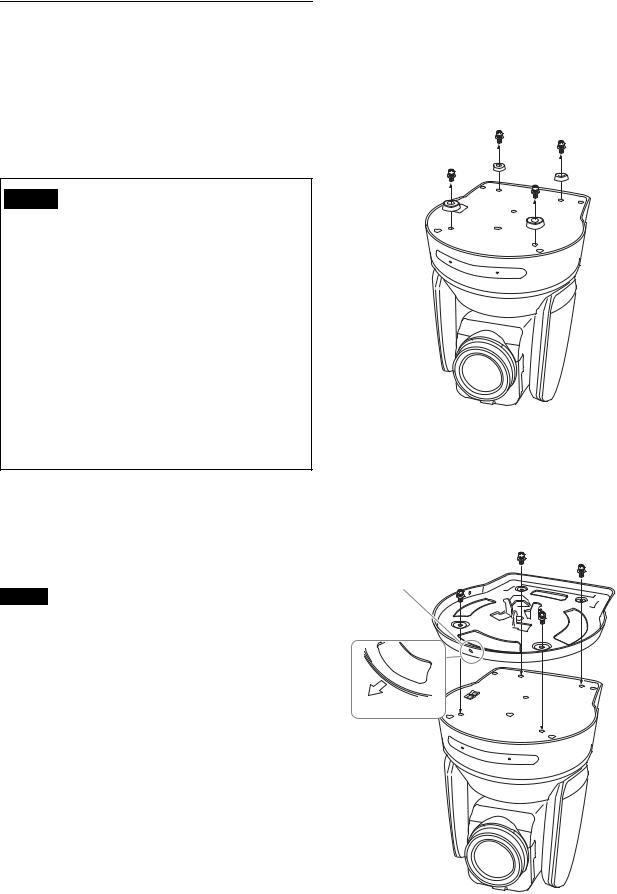
Installing the camera on the ceiling (example)
1 Turn on IMG FLIP in the SYSTEM menu.
2 Loosen the four screws at the bottom of the camera to remove the four feet.
3 Attach the ceiling bracket (A) to the bottom of the camera by using supplied four screws (3 M3×8).
Align the a mark of the bracket (A) with the front of the camera as illustrated, with the screw holes of the bracket aligned to the screw holes of the camera.
3 M3×8 (supplied)
Ceiling bracket (A)
a mark
Front of the camera
16
Caution
Use the supplied screws. Otherwise, you may break the internal parts of the camera.
4 Attach the ceiling bracket (B) to the attachment materials (not supplied) to mount the camera on the ceiling.
Be sure to attach it so that the f hole of the ceiling bracket (B) is placed where the front of the camera will face.
Attachment materials
Ceiling
 f hole
Ceiling bracket (B)
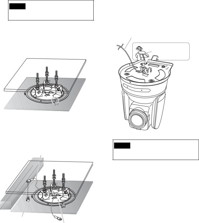
5 Attach the wire rope for fall prevention to the ceiling.
Using an M5 (3/16 inches) socket cap screw (not supplied), attach it to the attachment materials different from the one to which the ceiling bracket
(B) is attached.
Wire rope (supplied)
Attachment materials
Ceiling
6 Attach the wire rope for fall prevention to the ceiling bracket (A).
Put the wire rope through the fitting for wire rope of the ceiling bracket (A) and securely attach it to the bracket using the supplied stainless steel screw (3 M4×8).
Wire rope (supplied)
 3M4×8 (supplied)
Fitting for wire rope
Ceiling bracket (A)
Caution
Use the supplied screw. Otherwise, the wire rope may not function properly.
M5 (3/16 inch) socket
cap bolt
Ceiling bracket (B)
17

7 Aligning the a hole in the front of the ceiling bracket (A) to the ◊ hole of the ceiling bracket (B), push in the camera unit, and turn the camera with the ceiling bracket (A) clockwise to temporarily secure the camera.
Ceiling
3 M3×8 (supplied)
Ceiling |
Ceiling bracket |
|
(B) |
◊ mark |
1 |
|
|
Align |
|
a mark |
Ceiling |
bracket (A) |
|
|
2 |
8 Secure the ceiling brackets (A) and (B) using supplied three screws (3 M3×8).
9-1Connect the cables to the terminals at the back of the camera.
Ceiling
Notes
•Make sure no load is applied to the connectors of the cables.
•For measures that prevent the cord of the AC adapter (not supplied) from being pulled out, see “Connecting the Camera” (page 23).
•For measures that prevent the HDMI cable from being pulled out, proceed to “9-2” after connecting the HDMI cable. Then, connect all the other cables.
18

9-2To help prevent the HDMI cable from being pulled out, remove the HDMI cable locking screw (M2.6×6, black), and use it to attach the supplied HDMI cable fixing plate to the back of the camera. Secure the HDMI cable with a commercially available tie-wrap.
Installing the camera on a shelf located at a high spot (example)
1 Loosen the four screws at the bottom of the camera to remove the four feet.
HDMI cable locking screw (M2.6×6, black)
Tie-wrap (commercially
available)
HDMI cable fixing plate (supplied)
Note
Do not leave the HDMI cable attached to the camera if you do not use it.
10Flip the SONY nameplate and 4K or HD nameplate around as necessary.
How to remove the camera
1 Remove the three screws which secured the camera in Step 8 of “Installing the camera on the ceiling (example)”.
2 Turn the camera unit counter-clockwise to remove it.
2 Attach the ceiling bracket (A) to the bottom of the camera by using supplied four screws (3 M3×8).
Align the a mark of the bracket (A) with the front of the camera as illustrated, with the screw holes of the bracket aligned to the screw holes of the camera.
3 M3×8 (supplied)
a mark
Front of the
camera
Ceiling bracket (A)
Note
Use the supplied screws. Otherwise, you may break the internal parts of the camera.
19

3 Attach the wire rope for fall prevention to the ceiling bracket (A).
Put the wire rope through the fitting for wire rope of the ceiling bracket (A) and securely attach it to the bracket using the supplied stainless steel screw (3 M4×8).
Wire rope (supplied)
3M4×8 (supplied)
Fitting for wire rope
Ceiling bracket
(A)
Caution
Use the supplied screw. Otherwise, the wire rope may not function properly.
4 Mount the ceiling bracket (B) onto the shelf where the camera will be mounted.
Use four screws (not supplied). Choose the right type of screws for the material of the shelf.
Be sure to attach it so that the f hole of the ceiling bracket (B) is placed where the front of the camera will face.
Wall
Screws (4)
Ceiling bracket
(B)
f hole
Hole for connecting cable
Shelf
20
 Loading...