


3-903-973-03 (1)
HD Optical
Multiplex Unit
|
__________________________________________ |
JP |
|
|
|
|
|
Operating Instructions |
__________________________________ |
GB |
|
|
|
|
|
Mode d’emploi |
________________________________________ |
FR |
|
|
|
|
|
Manual de instrucciones |
________________________________ |
ES |
|
|
|
|
|
Gebrauchsanweisung |
__________________________________ |
DE |
|

あとは、いつでも見られるところに必ず保管してください。
BRU-H700
© 2005 Sony Corporation
4 5
a
b
JP 2

|
|
....................................................................................... |
6 |
................................................................................... |
6 |
................................................................ |
7 |
............................. |
8 |
............................................. |
9 |
....................................................................................... |
9 |
..................................................................................................... |
10 |
................................................................................ |
11 |
VISCA RS-422 ........... |
12 |
.............................................. |
12 |
JP
3 JP


1
|
|
|
|
|
|
|
|
|
|
|
|
|
|
|
|
|
|
|
|
|
|
|
|
|
|
|
|
|
|
||
|
|
|
|
|
|
|
|
|
|
|
|
|
|
|
|
|
|
|
|
|
|
|
|
|
|
|
|
|
|
|
|
|
|
|
|
|
|||
|
|
|
|
|
|
|
|
|
|
|
|
|
|
|
|
|
|
|
|
|
|
|
|
|
|
|
|
|
|
|
|
|
|
|
|
|
|
|
|
|
|
|
|
|
|
|
|
|
|
|
|
|
|
|
|
10 cm
の上に設置しない。
JP 4 |
|
|
|
|
|
|
|
|
|
|
|
|
|
|
|
|
|
|
|
||
|
|
|
|
AC |
|
|
||
|
||
|
||
|
|
|
|
|
||
|
||
|
||
|
AC
AC
 5 JP
5 JP
HD BRU-H700
HD 3CCD BRC-H700
BRCH700
HD BRC-H700 HDBRBK-H700
CCFC-M100HG 1,000m
2
RGB D-sub15 S RGB SD-SDI
HD-SDI VESA VGA XGA WXGA HDV
/
HD BRC-H700
R/L
HD BRC-H700 HDBRBK-H700
HD
BRC-H700
|
|
|
|
HD |
|
|
|
BRBK-H700 |
|
|
|
|
CCFC-M100HG |
|
|
|
||
CAMERA |
|
HD |
|
|
|
AUDIO |
|
|
L |
|
|
R |
|
|
FUNCTION |
~AC IN |
BRU-H700 |
1 6 |
||
VISCA RS-422 |
|
|
CAMERA IN EXT SYNC OUT RGB/COMPONENT IN VISCA RS-232C OUT |
|
|
|
|
|
 RGB/COMPONENT
 VISCA RS-232C IN
RGB/ |
|
|
D-sub |
|
15 |


HD |
RS-232C * |
RM-BR300 |
 VISCA RS-232C
|
|
|
|
RM-BR300 |
|
*VISCA RS-232C VISCA RS-422VISCA RS-422
BRC-H700BRU-H700Communication error Please check connection
JP 6

1 2 3
BRC-H700
CDATA MIX
信号にメニュー画面を重ねて表示するときONOFF
4 |
|
5 6 |
|
|
|
AUDIO OUT |
|
|
|
L |
|
|
|
R |
|
|
|
FUNCTION ~AC IN |
|
|
|
1 |
6 |
|
|
VISCA RS-422 |
|
CAMERA IN EXT SYNC OUT |
RGB/COMPONENT |
IN VISCA RS-232C OUT |
|
7 8 9 |
0 |
qa qs qd |
qf |
HFBK-SD1 HFBK-HD1 HFBK-XG1 HFBK-TS1
EAUDIO OUT L/R
HDBRBK-H700 AUDIO IN
FAC IN
GCAMERA
CCFC-M100HGBRC-H700 HDBRBK-H700
HEXT SYNC IN
IEXT SYNC OUT
EXT SYNC IN
J  RGB/COMPONENT
YPbPr RGB
KVISCA RS-232C IN
RM-BR300VISCA RS-232C OUT
LVISCA RS-232C OUT
VISCA RS-232C IN
MVISCA RS-422
HDBRU-H700 VISCA RS-422
VISCA RS-422 VISCA RS-422 12
NVISCA FUNCTION
VISCA
RS-232C/RS-422
ON RS-422 OFF RS-232C
7 JP

2
ON 38400bps OFF
9600bps
3 5
と、リモートコントロールユニットRM-BR300 RESET POWER1 7
|
0 |
1 |
2 |
3 |
4 |
5 |
6 |
7 |
|
|
|
|
|
|
|
|
|
|
OFF |
ON |
OFF |
ON |
OFF |
ON |
OFF |
ON |
3 |
|
|
|
|
|
|
|
|
|
|
|
|
|
|
|
|
|
|
OFF |
OFF |
ON |
ON |
OFF |
OFF |
ON |
ON |
4 |
|
|
|
|
|
|
|
|
|
|
|
|
|
|
|
|
|
|
OFF |
OFF |
OFF |
OFF |
ON |
ON |
ON |
ON |
5 |
|
|
|
|
|
|
|
|
|
|
|
|
|
|
|
|
|
6 59.94i/50i
ON 50iOFF 59.94i
ドHFBK-SD1
1 2
2
3
JP 8

( 0 40 )
|
1080/59.94i 1080/50i VISCA |
|
FUNCTION |
|
/ |
|
16 9 |
S/N |
50 dB |
LC Duplex Fiber 1D-sub 15
RGB 0.7 Vp-p 75Ω
1 Vp-p ± 0.3V 3 75Ω
コンポーネント
Y 1 Vp-p ± 0.3V 3 75Ω
Pb/Pr ± 350 mVp-p 75Ω
HD/VD Sync 1 Vp-p 75Ω
3 Sync ± 300 mVp-p 75Ω
/
EXT SYNC IN BNC 1 3 ± 300 mVp-p
SD sync 2 V
EXT SYNC OUT BNC 1
/
VISCA RS-232C IN 8 DIN1
VISCA RS-232C OUT 8 DIN1
VISCA RS-422 9 1
9600 bps/38400 bps
8 1
R 1 L 1
2.8 Vrms1 kΩ1 kHz
|
AC 100 V 50/60 Hz |
|
0.4 A |
|
8 W |
|
|
|
0 40 |
|
20 60 |
/ 9 JP
|
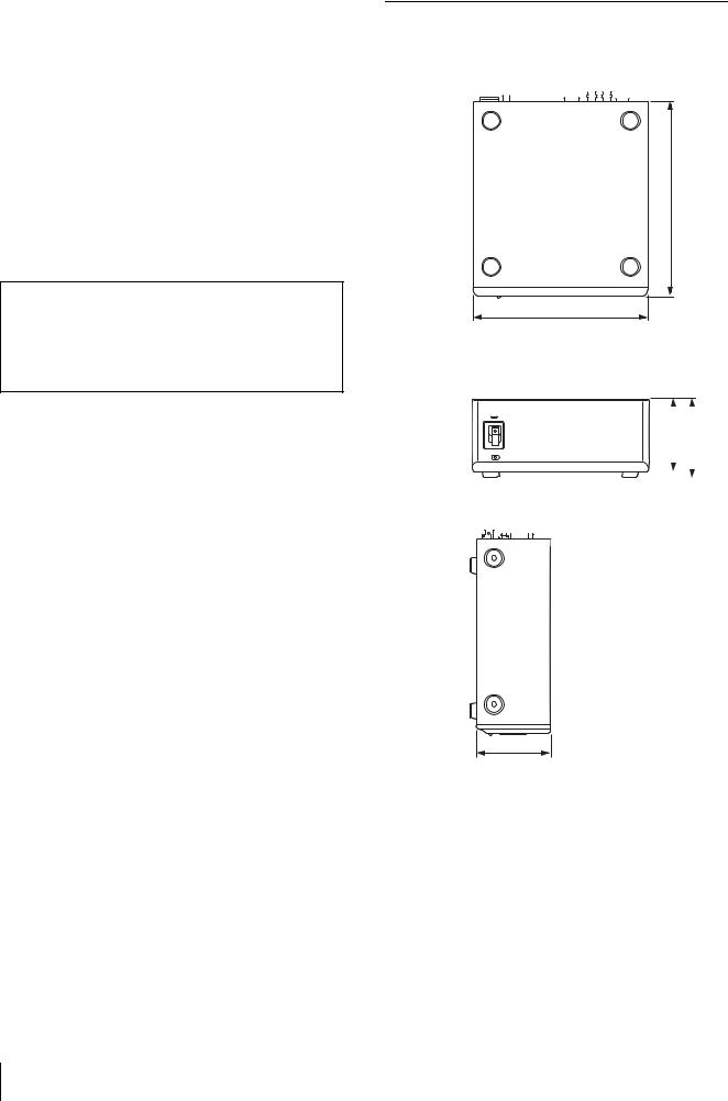
210 × 86 × 240 mm |
|
|
|
2.4 kg |
1
RS-232C 1
RS-422 1
11
(VCCI A
240
210
86 |
|
94 |
|
||
|
|
|
|
|
|
|
|
|
|
|
|
|
|
|
|
|
|
86
mm
JP 10
VISCA RS-422 ( 9 )
VISCA RS-232C IN 8 DIN |
|
|
VISCA RS-422 |
|
|
|
|
|
|||||
|
|
|
|
|
|
|
|
|
|
|
|
||
|
|
|
|
|
|
|
|
|
|
|
|
|
|
|
|
1 |
2 |
3 |
4 |
5 |
6 |
7 |
8 |
9 |
|
||
|
|
|
|
|
|
|
|
|
|
|
|
|
|
|
|
|
|
|
|
|
|
|
|
|
|
||
|
IN VISCA RS-232C |
|
1 |
|
RXD OUT |
|
|
|
|
||||
|
|
|
2 |
|
RXD OUT + |
|
|
|
|
||||
|
|
|
|
|
|
|
|||||||
|
3 |
|
TXD OUT |
|
|
|
|
||||||
1 |
DTR IN |
|
|
|
|
|
|||||||
|
4 |
|
TXD OUT + |
|
|
|
|
||||||
2 |
DSR IN |
|
|
|
|
|
|||||||
|
5 |
|
GND |
|
|
|
|
|
|
||||
3 |
TXD IN |
|
|
|
|
|
|
|
|||||
|
6 |
|
RXD IN |
|
|
|
|
|
|||||
4 |
GND |
|
|
|
|
|
|
||||||
|
7 |
|
RXD IN + |
|
|
|
|
|
|||||
5 |
RXD IN |
|
|
|
|
|
|
||||||
|
8 |
|
TXD IN |
|
|
|
|
|
|||||
6 |
GND |
|
|
|
|
|
|
||||||
9 |
|
TXD IN + |
|
|
|
|
|
||||||
|
|
|
|
|
|
|
|
||||||
8 |
RGB/COMPONENT D-sub 15 |
VISCA RS-232C OUT 8 DIN
|
|
|
|
RGB/COMPONENT |
|
|
|
|
|
||
VISCA RS-232C OUT |
|
|
|
|
|
|
|
|
|
||
|
|
|
|
|
|
|
|
|
|
|
|
|
|
|
|
|
|
|
|
|
|
|
|
|
|
|
|
|
|
|
|
||||
|
|
|
|
|
|
|
|
|
|
|
|
1 |
DTR OUT |
|
|
|
|
|
|
|
|||
|
YPbPr |
YPbPr |
RGB |
RGB |
|||||||
2 |
DSR OUT |
|
|
COMPONEN |
COMPONENT |
|
|
|
SYNC |
VD |
|
|
|
|
|
|
|||||||
|
|
|
|
|
|||||||
3 |
TXD OUT |
|
|
T |
VD |
|
|
|
|
|
|
4 |
GND |
1 |
Pr-OUT |
Pr-OUT |
R-OUT |
R-OUT |
|||||
5 |
RXD OUT |
|
|
|
|
|
|
|
|
|
|
2 |
Y-OUT |
Y-OUT |
G-OUT |
G-OUT |
|||||||
6 |
GND |
|
|
|
|
|
|
|
|
|
|
3 |
Pb-OUT |
Pb-OUT |
B-OUT |
B-OUT |
|||||||
|
|
||||||||||
|
|
4 |
GND |
GND |
GND |
GND |
|
8 |
|
||||||
|
|
|
|
|
|
||
|
|
|
|
|
|||
|
|
5 |
GND |
GND |
GND |
GND |
|
|
|
||||||
|
|
|
|
|
|
|
|
|
6 |
GND |
GND |
GND |
GND |
||
|
|
|
|
|
|
|
|
|
7 |
GND |
GND |
GND |
GND |
||
|
|
|
|
|
|
|
|
|
8 |
GND |
GND |
GND |
GND |
||
|
|
|
|
|
|
|
|
|
9 |
NC |
NC |
NC |
NC |
||
|
|
|
|
|
|
|
|
|
10 |
GND |
GND |
GND |
GND |
||
|
|
|
|
|
|
|
|
|
11 |
GND |
GND |
GND |
GND |
||
|
|
|
|
|
|
|
|
|
12 |
NC |
NC |
NC |
NC |
||
|
|
|
|
|
|
|
|
|
13 |
HD-OUT |
HD-OUT |
HD-OUT |
HD-OUT |
||
|
|
|
|
|
|
|
|
|
14 |
3 SYNC- |
2 VD-OUT |
3 SYNC- |
2 VD- |
||
|
|
|
|
OUT |
|
OUT |
OUT |
|
|
|
|
|
|
|
|
|
15 |
NC |
NC |
NC |
NC |
||
11 JP
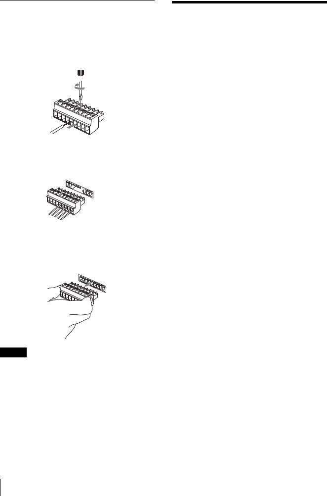
VISCA RS-422
1 AWG No.28 18

2 VISCA RS-422 VISCA RS-422
1 

9
VISCA RS-422
1
9
GND
VISCA RS-422 VISCA RS-232C
VISCA RS-422 1,200 m
JP 12

Owner’s Record
The model and serial numbers are located on the top. Record the serial number in the space provided below. Refer to these numbers whenever you call upon your Sony dealer regarding this product.
Model No. BRU-H700
Serial No.
WARNING
To reduce a risk of fire or electric shock, do not expose this product to rain or moisture.
To avoid electrical shock, do not open the cabinet. Refer servicing to qualified personnel only.
WARNING
THIS APPARATUS MUST BE EARTHED.
WARNING
The mains plug on this equipment must be used to disconnect mains power.
Please ensure that the socket outlet is installed near the equipment and shall be easily accessible.
In the event of abnormal operations, disconnect the mains plug.
Laser Notice :
This product contains an optical fiber connecter using laser that complies with EN 60825-1.
This product is classified as a CLASS 1 LASER PRODUCT.
Laser Diode information ( Optical Fiber Connector ) Wavelength 850 nm
CAUTION
The use of controls or adjustments or performance of procedures other than those specified herein may result in hazardous radiation exposure.
CAUTION
Do not look at the end of optical connector with naked eyes or through optical equipment while the power is supplied to this product. Otherwise, your eyes may be injured.
ATTENTION
The electromagnetic fields at the specific frequencies may influence the picture of this unit.
For customers in the U.S.A.
This device complies with part 15 of the FCC Rules. Operation is subject to the following two conditions:
(1) this device may not cause harmful interference, and (2) this device must accept any interference received, including interference that may cause undesired operation.
This equipment has been tested and found to comply with the limits for a Class A digital device, pursuant to Part 15 of the FCC Rules. These limits are designed to provide reasonable protection against harmful interference when the equipment is operated in a commercial environment. This equipment generates, uses, and can radiate radio frequency energy and, if not installed and used in accordance with the instruction manual, may cause harmful interference to radio communications. Operation of this equipment in a residential area is likely to cause harmful interference in which case the user will be required to correct the interference at his own expense.
You are cautioned that any changes or modifications not expressly approved in this manual could void your authority to operate this equipment.
All interface cables used to connect peripherals must be shielded in order to comply with the limits for a digital device pursuant to Subpart B of Part 15 of FCC Rules.
For the customers in Canada
This Class A digital apparatus complies with Canadian ICES-003.
Pour les utilisateurs au Canada
Cet appareil numérique de la classe A est conforme à la norme NMB-003 du Canada.
For the customers in Europe
Warning
This is a Class A product. In a domestic environment, this product may cause radio interference in which case the user may be required to take adequate measures. In the case that interference should occur, consult your nearest authorized Sony service facility.
INTERFACE CABLE
This device requires shielded interface cables to comply with FCC emission limits.
GB 2

Table of Contents |
|
Features .................................................................. |
4 |
Connecting Cables .............................................. |
4 |
Example of System Configuration ..................... |
4 |
Location and Function of Parts ............................ |
5 |
Attaching an Interface Board ............................... |
6 |
Precautions ............................................................. |
7 |
Specifications .......................................................... |
7 |
Dimensions ......................................................... |
8 |
Pin Assignments ................................................. |
9 |
Using the VISCA RS-422 Connector Plug ...... |
10 |
GB
Table of Contents 3 GB
Features
The BRU-H700 HD Optical Multiplex Unit is designed to connect the BRC-H700 HD 3CCD Color Video Camera.
Long-distance transmission via optical fiber cable (BRC-H700 only)
The BRU-H700 is equipped with a camera connector to allow the connection of multiplex optical fiber cable. You can connect the BRC-H700 HD camera from up to 1,000 m (3,281 feet) away by inserting the BRBK-H700 HD Optical Multiplex Card into the HD camera and using the CCFC-M100HG Optical Fiber Cable.
Two interface card slots equipped
The BRU-H700 is equipped as standard with an RGB/ component video output (D-sub 15-pin). In addition to this connector, two interface card slots allow the unit to be equipped with various analog signal outputs such as composite video, S video, component video and RGB outputs, and digital signal outputs such as SD-SDI signal, HD-SDI signal, VESA standard signal (VGA, XGA and WXGA) and HDV standard signal outputs.
External sync signal input/output equipped
When multiple BRC-H700 HD cameras are connected via the Optical Fiber Cable, the video signal can be synchronized by inputting the sync signal into the external sync input connector.
Audio line output connectors (phono jacks, R/ L) equipped
The BRU-H700 allows output of stereo audio line signals that are transmitted from the BRBK-H700 HD Optical Multiplex Card inserted into the BRC-H700 HD camera.
Connecting Cables
Use the following connecting cable to connect devices in this system.
Cable |
Part No. |
Number |
RS-232C cable |
1-590-879-3X |
1 |
(3m (10feet)) |
|
|
|
|
|
RS-232C cable
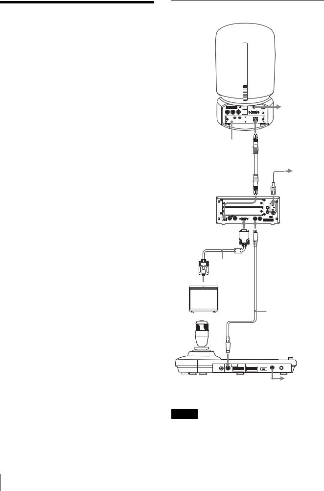
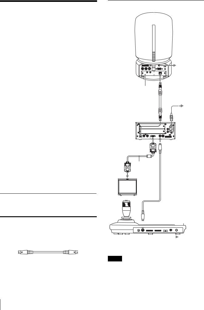
Example of System Configuration
HD camera
BRC-H700
|
to AC outlet |
|
Optical connector |
BRBK-H700 HD Optical |
|
Multiplex Card |
|
CCFC-M100HG Optical |
AC power cord |
Fiber Cable |
(supplied) |
|
to AC |
CAMERA |
outlet |
|
|
BRU-H700 HD |
AUDIO |
Optical Multiplex |
L |
|
FUNCTION |
Unit (this unit) |
R |
|
1 6 ~AC IN |
|
VISCA RS-422 |
|
CAMERA IN EXT SYNC OUT |
RGB/COMPONENT |
IN VISCA RS-232C OUT |
 RGB/
RGB/
COMPONENT
connecting cable with D-sub 15-pin connectors
to RGB/ component input
HD monitor, etc.
 VISCA RS-232C IN
 RS-232C cable (supplied with the RM-BR300)*
 VISCA RS-232C
|
|
|
|
|
|
|
|
|
|
|
|
|
|
|
|
|
|
|
|
|
|
|
|
|
|
|
|
|
|
|
RM-BR300 Remote Control Unit |
|
to AC outlet |
||||||||||||||||||||||||||||
|
||||||||||||||||||||||||||||||
*The VISCA RS-422 connection is also available if you use the VISCA RS-422 connectors.
Note
To start the system, first turn on the power of the BRCH700 camera, then turn on the power of the BRU-H700 (this unit). Otherwise, the error message “Communication error Please check connection” may appear.
GB 4 Features
Location and Function
of Parts
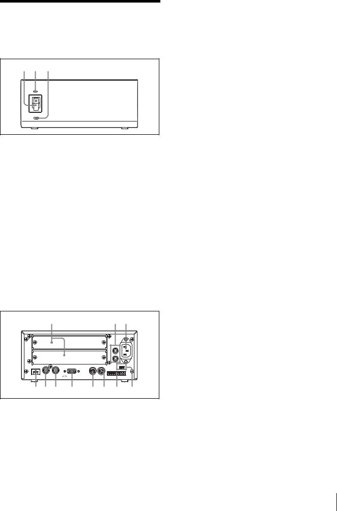
Front
1 2 3
APower switch
Turns on/off the power of this unit.Turn on the power of the BRC-H700 camera before you turn on this unit.
BPower indicator
Lit in green: This unit is in normal operation. Lit in red: The power of the camera connected to this unit is turned off. Turn it on.
Flashing in red: Abnormal operation of this unit. Display the composite video signal on the monitor and check the error message. Check also the connection.
CDATA MIX switch
Set the switch to ON to overlap the menu with the video signal output from the installed interface board. Set it to OFF not to overlap the menu.
Rear
4 |
|
5 6 |
|
|
|
AUDIO OUT |
|
|
|
L |
|
|
|
R |
|
|
|
FUNCTION ~AC IN |
|
|
|
1 |
6 |
|
|
VISCA RS-422 |
|
CAMERA IN EXT SYNC OUT |
RGB/COMPONENT |
IN VISCA RS-232C OUT |
|
7 8 9 |
0 |
qa qs qd |
qf |
DCard slot
Insert an optional interface board, HFBK-SD1, HFBK-HD1, HFBK-XG1 or HFBK-TS1.
The slot cover is attached to the unit at the factory.
EAUDIO OUT L/R jacks
Loop through output of the audio line signal input from the AUDIO IN jacks on the BRBK-H700 HD
Optical Multiplex Card inserted into the camera via the Optical Fiber Cable.
F~AC IN connector
Connect the supplied AC power cord.
GCAMERA connector
Connect to the optical connector of the BRBKH700 HD Optical Multiplex Card installed in the BRC-H700 camera using the CCFC-M100HG Optical Fiber Cable.
A dustproof cap is attached at the factory.
HEXT SYNC IN connector
Accepts external video sync signals.
IEXT SYNC OUT connector
Supplies external video sync signals input from the EXT SYNC IN connector.
J RGB/COMPONENT connector
Supplies the images from the camera as YPbPr or RGB signal.
KVISCA RS-232C IN connector
Connect to the RM-BR300 Remote Control Unit (not supplied). When you connect multiple cameras, connect it to the VISCA RS-232C OUT connector of the previous camera in the daisy chain connection.
LVISCA RS-232C OUT connector
When you connect multiple cameras, connect it to the VISCA RS-232C IN connector of the next camera in the daisy chain connection.
MVISCA RS-422 connector
Connect to the VISCA RS-422 connector of the camera or another BRU-H700 HD Optical Multiplex Unit.
For the connection to the VISCA RS-422 connector, see “Using the VISCA RS-422 Connector Plug” on page 10.
NVISCA FUNCTION switches
These switches are used for the VISCA communication settings.
Switch 1 (RS-232C/RS-422 selector)
Set to ON for RS-422, or OFF for RS-232C.
Switch 2 (Communication baud rate selector)
Set to ON for 38400bps, or OFF for 9600bps.
Location and Function of Parts 5 GB
 Loading...