


DIGITAL VIDEOCASSETTE RECORDER
DVW-A500/1
DVW-500/1 DVW-A500P/1 DVW-500P/1
CONTROL PANEL
BKDW-515
INSTALLATION AND MAINTENANCE MANUAL 1st Edition (Revised 3)
!WARNING
This manual is intended for qualified service personnel only.
To reduce the risk of electric shock, fire or injury, do not perform any servicing other than that contained in the operating instructions unless you are qualified to do so. Refer all servicing to qualified service personnel.
!WARNUNG
Die Anleitung ist nur für qualifiziertes Fachpersonal bestimmt.
Alle Wartungsarbeiten dürfen nur von qualifiziertem Fachpersonal ausgeführt werden. Um die Gefahr eines elektrischen Schlages, Feuergefahr und Verletzungen zu vermeiden, sind bei Wartungsarbeiten strikt die Angaben in der Anleitung zu befolgen. Andere als die angegeben Wartungsarbeiten dürfen nur von Personen ausgeführt werden, die eine spezielle Befähigung dazu besitzen.
!AVERTISSEMENT
Ce manual est destiné uniquement aux personnes compétentes en charge de l’entretien. Afin de réduire les risques de décharge électrique, d’incendie ou de blessure n’effectuer que les réparations indiquées dans le mode d’emploi à moins d’être qualifié pour en effectuer d’autres. Pour toute réparation faire appel à une personne compétente uniquement.
DVW-A500/1 Serial No. 50001 and Higher
DVW-500/1 Serial No. 50001 and Higher
DVW-A500P/1 Serial No. 50001 and Higher
DVW-500P/1 Serial No. 50001 and Higher
BKDW-515 Serial No. 10001 and Higher
BKDW-515
CAUTION
Danger of explosion if battery is incorrectly replaced.
Replace only with the same or equivalent type recommended by the manufacturer.
Dispose of used batteries according to the manufacturer's instructions.
Vorsicht!
Explosionsgefahr bei unsachgemäßem Austausch der Batterie.
Ersatz nur durch denselben oder einen vom Hersteller empfohlenen ähnlichen Typ.
Entsorgung gebrauchter Batterien nach Angaben des Herstellers.
ATTENTION
Il y a danger d'explosion s'il y a remplacement incorrect de la batterie.
Remplacer uniquement avec une batterie du même type ou d'un type équivalent recommandé par le constructeur.
Mettre au rebut les batteries usagées conformément aux instructions du fabricant.
ADVARSEL!
Lithiumbatteri-Eksplosionsfare ved fejlagtig håndtering.
Udskiftning må kun ske med batteri af samme fabrikat og type.
Levér det brugte batteri tilbage til leverandøren.
Voor de klanten in Nederland
Dit apparaat bevat een (CF)n-Li batterij voor memory back-up.
Raadpleeg uw leverancier over de verwijdering van de batterij op het moment dat u het apparaat bij einde levensduur afdankt.
Gooi de batterij niet weg. maar lever hem in als KCA.
Bij dit produkt zijn batterijen geleverd. Wanneer deze leeg zijn, moet u ze niet weggooien maar inleveren als KCA.
BKDW-515
|
Table of Contents |
|
Manual Structure |
|
|
Purpose of this manual .............................................................................................. |
3 |
|
Contents ..................................................................................................................... |
3 |
|
Relative manuals ....................................................................................................... |
4 |
|
1. |
Installation |
|
1-1. Installation of Control Panel ....................................................................... |
1-1 |
|
1-2. SYS1, SYS2 ROM Versions ....................................................................... |
1-2 |
|
1-3. Removal of Control Panel / Replacement of Arms ..................................... |
1-2 |
|
1-4. Installation of Sub Panel Cover and Switch Cover ..................................... |
1-3 |
|
1-5. Installation of Control Panel ....................................................................... |
1-3 |
|
1-6. |
Installation Space ........................................................................................ |
1-4 |
1-7. Full Reset of Control Panel ......................................................................... |
1-5 |
|
1-8. Extension of Control Panel ......................................................................... |
1-5 |
|
2. |
Service Information |
|
2-1. Location and Function of Printed Circuit Boards ....................................... |
2-1 |
|
2-2. Replacing the Battery for Memory Backup ................................................ |
2-2 |
|
2-3. |
EL Panel Replacement ................................................................................ |
2-3 |
2-4. |
Error Message ............................................................................................. |
2-4 |
|
2-4-1. Operation when Checksum Error |
|
|
of Current Setup Data Occurs .................................................... |
2-4 |
|
2-4-2. Correction when Checksum Error |
|
|
of VTR Bank Data Occurs ......................................................... |
2-4 |
|
2-4-3. Correction when Checksum Error |
|
|
of Memory Card Data Occurs .................................................... |
2-4 |
3. Setup Menu
3-1. ITEM-F Series ............................................................................................. |
3-1 |
BKDW-515 |
1 |
4. |
Maintenance Menu |
|
|
4-1. |
ROM Version .............................................................................................. |
4-1 |
|
4-2. |
VTR Maintenance Menu ............................................................................. |
4-1 |
|
4-3. |
Panel Maintenance Menu ............................................................................ |
4-2 |
|
|
4-3-1. |
Card Interface Test ..................................................................... |
4-2 |
|
4-3-2. |
Buzzer Test ................................................................................. |
4-2 |
|
4-3-3. |
EL Panel Test ............................................................................. |
4-3 |
|
4-3-4. |
Key Test ..................................................................................... |
4-3 |
|
4-3-5. |
Dial Test ..................................................................................... |
4-3 |
4-4. |
Error Logger ................................................................................................ |
4-4 |
|
5.Block Diagram
6.Spare Parts
6-1. |
Notes on Repair Parts .................................................................................. |
6-1 |
6-2. |
Spare Parts List for VTR ............................................................................. |
6-2 |
6-3. |
Packing Materials and Supplied Accessories List for VTR ........................ |
6-3 |
6-4. |
Spare Parts List for Control Panel ............................................................... |
6-4 |
6-5 |
Packing Materials and Supplied Accessories List for BKDW-515 ............ |
6-6 |
2 |
BKDW-515 |

Manual Structure
Purpose of this manual
This Manual describes the installation instructions for the digital videocassette recorder DVW-A500/1, 500/1, A500P/1, 500P/1 and the Control panel BKDW-515. This manual contains the information necessary when supplying and installing the unit, assuming use by system/service engineers.
Contents
The sections covered in the manual are summarized below to give you a general under standing of the manual.
Section 1 Installation
Explains the installation of the control panel.
Section 2 Service Overview
Explains replacement of the memory backup battery and EL panel.
Section 3 Setup Menu
Explains Setup menu of ITEM-F series only. As for ITEM-H00 to ITEM-900 series, refer to Operation Manual.
Section 4 Maintenance Menu
Explains VTR Maintenance Menu and PANEL Maintenance menu.
Section 5 Block Diagram
Describes the overall block diagram.
Section 6 Spare parts
Describes the exploded views for the this unit, mounted boards list, packing list, and standard accessories list.
BKDW-515 |
3 |

Relative manuals
Besides this “Installation and Maintenance Manual”, the following manuals are available.
•Operation Manual (Supplied with the VTR or the BKDW-515)
This manual is necessary for application and operation of the VTR.
•Installation Manual (Supplied with the VTR)
This manual describes the items are required to install the VTR and its peripherals.
If the BKDW-514 control panel is used, refer to this manual.
• Maintenance Manual Part 1 (Supplied with the VTR)
This manual describes the periodic maintenance and servicing information necessary for the principal block and board replacement.
• Maintenance Manual Part 2 (available on request)
These manuals describes detailed information necessary for general parts replacement and includes alignments, schematic diagrams, board layouts, detailed parts list, etc.
Please contact the Sony service organization to obtain a copy of the manuals.
•Protocol Manual (available on request) PROTOCOL OF REMOTE-1 (9Pin) CONNECTOR
This Manual describes the protocol information necessary for controlling the VTR via RS-422A (9-pin serial remote).
4 |
BKDW-515 |
Section 1
Installation
n
The BKDW-515 cannot be installed in the BKDW-511 Control Panel Case.
for DVW-A500/1, DVW500/1, DVW-A500P/1, DVW-500P/1
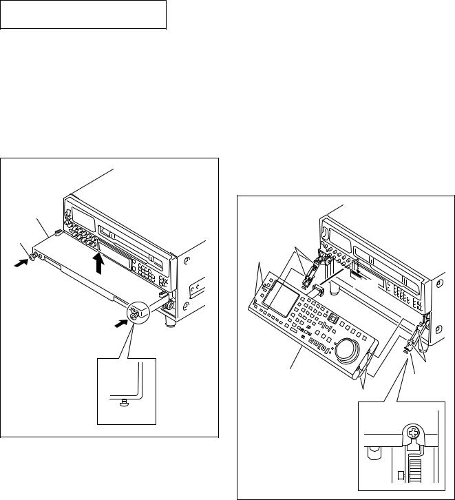
1-1. Installation of Control Panel
1.Fix a dummy panel for shipping use at 90 degrees.
2.Loosen the two black screws on the dummy panel. (Loosen the screws until screw’s top are exposed from the surface of the dummy panel.)
3.While pushing the loosened black screws in the direction of the arrow, remove the dummy panel assembly from the arms.
Dummy panel |
Screw |
(B3x12) |
Screw(B3x12) |
BKDW-515
4.Fix the both arms at 45 degrees.
5.Connect the harness of the control panel to the connector (CN580) on the system set-up panel.
6.Set the notches of the control panel to the claws of the arms, and push the control panel until making a click sound.
n
Push the head of the two screws when the hook does not move smoothly and when the panel is difficult to attach. This facilitates the attaching.
7.Then tighten the two screws.
Claws |
Notches |
CN580 |
Claws |
Control panel |
Screw |
(B3x12) |
Notches |
1-1 |

1-2. SYS1, SYS2 ROM Versions
1-3. Removal of Control Panel / Replacement of Arms
for DVW-A500, DVW500, DVW-A500P, DVW-500P
1-2. SYS1, SYS2 ROM Versions
The control panel BKDW-515 is applicable to the ROMs on the SS-52 board with the following version.
SYS1: 4.0 and higher SYS2: 4.0 and higher
If the ROMs with lower version than above are used, please contact Sony’s service organization.
Make sure the ROM’s version through the maintenance mode before replacement of the control panel.
1-3. Removal of Control Panel /
Replacement of Arms
1.Fix a lower control panel at 90 degrees.
2.Disconnect the connector (CN580) in the system setup panel.
3.Loosen the two black screws on the lower control panel. (Loosen the screws until screw’s top are exposed from the surface of the lower control panel.)
Lower control panel |
|
|
|
System setup |
|
CN580 |
panel. |
Screw(B3x12) |
1-2
4.While pushing the loosened black screws in the direction of the arrow, remove the lower control panel assembly from the arms.
Lower control panel
Screw(B3x12)
Screw(B3x12)
5.Remove the screws as shown in Figure, and remove both side arms.
Screws |
(B3x6) |
Screw |
(B3x6) |
Arm |
6. Install the arms supplied with BKDW-515. |
SLIDER AD (R) ASSY: X-3678-375- |
SLIDER AD (L) ASSY: X-3678-376- |
Screws |
(B3x6) |
Screw |
(B3x6) |
Arm |
BKDW-515 |
1-4. Installation of Sub Panel Cover and
Switch Cover
1.Install the sub panel cover supplied with BKDW-515 to sub control panel.
Screw |
(BVTT3x6) |
Sub panel cover |
Screw |
(BVTT3x6) |
2.Install the switch cover supplied with BKDW-515 to system set-up panel.
Screw |
(BVTT3x6) |
Switch cover |
Screw |
(BVTT3x6) |
1-4. Installation of Sub Panel Cover and Switch Cover 1-5. Installation of Control Panel
1-5. Installation of Control Panel
1.Fix the both arms at 45 degrees.
2.Connect the harness of the control panel to the connector (CN580) on the system set-up panel.
3.Set the notches of the control panel to the claws of the arms, and push the control panel until making a click sound.
n
Push the head of the two screws when the hook does not move smoothly and when the panel is difficult to attach. This facilitates the attaching.
4.Then tighten the two screws.
Claws |
Notches |
CN580 |
Claws |
Control panel |
Screw |
(B3x12) |
Notches |
BKDW-515 |
1-3 |
 Loading...