


BKDS-7003
Table of contents
 Loading...
Sony BKDS-7003, DVS-7150, BKDS-7031, BKDS-7030, BKDS-7075 Installation Manual
...
DIGITAL VIDEO SWITCHER
DVS-7150
SWITCHER CONTROL PANEL
BKDS-7017
BKDS-2031
BKDS-7001
BKDS-7003
BKDS-7030
BKDS-7031
BKDS-7033
BKDS-7075
BKDS-7091
BKDS-7110
BKDS-7111
BKDS-7113
BKDS-7161
BKDS-7163
BKDS-7280
BKDS-M1690
BZS-7080
BKDS-7134
INSTALLATION MANUAL
1st Edition

! WARNING
This manual is intended for qualified service personnel only.
To reduce the risk of electric shock, fire or injury, do not perform any servicing other than that
contained in the operating instructions unless you are qualified to do so. Refer all servicing to
qualified service personnel.
! WARNUNG
Die Anleitung ist nur für qualifiziertes Fachpersonal bestimmt.
Alle Wartungsarbeiten dürfen nur von qualifiziertem Fachpersonal ausgeführt werden. Um die
Gefahr eines elektrischen Schlages, Feuergefahr und Verletzungen zu vermeiden, sind bei
Wartungsarbeiten strikt die Angaben in der Anleitung zu befolgen. Andere als die angegeben
Wartungsarbeiten dürfen nur von Personen ausgeführt werden, die eine spezielle Befähigung
dazu besitzen.
! AVERTISSEMENT
Ce manual est destiné uniquement aux personnes compétentes en charge de l’entretien. Afin
de réduire les risques de décharge électrique, d’incendie ou de blessure n’effectuer que les
réparations indiquées dans le mode d’emploi à moins d’être qualifié pour en effectuer d’autres.
Pour toute réparation faire appel à une personne compétente uniquement.
DVS-7150 Serial No. 10001 and Higher
BKDS-2031 Serial No. 10001 and Higher
BKDS-7001 Serial No. 10001 and Higher
BKDS-7003 Serial No. 10001 and Higher
BKDS-7017 Serial No. 10001 and Higher
BKDS-7030 Serial No. 10001 and Higher
BKDS-7031 Serial No. 10001 and Higher
BKDS-7033 Serial No. 10001 and Higher
BKDS-7075 Serial No. 10001 and Higher
BKDS-7091 Serial No. 10001 and Higher
BKDS-7110 Serial No. 10001 and Higher
BKDS-7111 Serial No. 10001 and Higher
BKDS-7113 Serial No. 10001 and Higher
BKDS-7134 Serial No. 10001 and Higher
BKDS-7161 Serial No. 10001 and Higher
BKDS-7163 Serial No. 10001 and Higher
BKDS-7280 Serial No. 10001 and Higher
BKDS-M1690 Serial No. 10001 and Higher
BZS-7080 Serial No. 10001 and Higher

WARNING
This unit has no power switch.
When installing the unit, incorporate a readily
accessible disconnect device in the fixed wiring, or
connect the power cord to a socket-outlet which must be
provided near the unit and easily accessible, so that the
user can turn off the power in case a fault should occur.
WARNUNG
Dieses Gerät hat keinen Netzschalter.
Beim Einbau des Geräts ist daher im Festkabel ein leicht
zugänglicher Unterbrecher einzufügen, oder das
Netzkabel mu
befindlichen, leicht zugänglichen Wandsteckdose
verbunden werden, damit sich bei einer
Funktionsstörung die Stromversorgung zum Gerät
jederzeit unterbrechen lä
Attention-when the product is installed in Rack:
1. Prevention against overloading of branch circuit
When this product is installed in a rack and is
supplied power from an outlet on the rack, please
make sure that the rack does not overload the supply
circuit.
ß
mit einer in der Nähe des Geräts
ß
t.
2. Providing protective earth
When this product is installed in a rack and is
supplied power from an outlet on the rack, please
confirm that the outlet is provided with a suitable
protective earth connection.
3. Internal air ambient temperature of the rack
When this product is installed in a rack, please make
sure that the internal air ambient temperature of the
rack is within the specified limit of this product.
4. Prevention against achieving hazardous
condition due to uneven mechanical loading
When this product is installed in a rack, please make
sure that the rack does not achieve hazardous
condition due to uneven mechanical loading.


Table of Contents
Manual Structure
Purpose of this manual .............................................................................................. 3
Related manuals......................................................................................................... 3
Contents ..................................................................................................................... 4
1. Installation
1-1. Operating Environment............................................................................... 1-1
1-2. Power Supply .............................................................................................. 1-1
1-2-1. Power Switch for Service (Control panel) .................................1-1
1-2-2. Power Specifications ..................................................................1-1
1-2-3. Power Cord.................................................................................1-1
1-3. Connectors...................................................................................................1-2
1-4. Input and Output Signals of Connectors ..................................................... 1-3
1-4-1. DVS-7150 ..................................................................................1-3
1-4-2. BKDS-7017................................................................................ 1-6
1-5. Example of System Connection ..................................................................1-8
2. Installation of DVS-7150
2-1. External Dimensions ................................................................................... 2-1
2-2. Rack Mounting............................................................................................ 2-2
3. Installation of Control Panel
3-1. External Dimensions ................................................................................... 3-1
3-2. Installation Space to Console ......................................................................3-2
3-3. Installation to Console.................................................................................3-3
3-4. Replacement of Key Tops........................................................................... 3-4
DVS-7150E IM
1

4. Installation of Options
4-1. Installation of Plug-in Boards .....................................................................4-2
4-2. Combination of Optional boards.................................................................4-4
4-2-1. Function of optional boards .......................................................4-4
4-2-2. Relation between optional boards and rear panel connectors ....4-4
4-3. Installation of Options for DVS-7150.........................................................4-6
4-3-1. Removing and Installing of Front Panel ....................................4-6
4-3-2. Inserting/Pulling Out of Plug-in Boards ....................................4-7
4-3-3. Installation of Optional Boards ..................................................4-8
4-3-4. Installation of BKDS-M1690
(Redundant Power Supply Unit) ..............................................4-11
4-4. Installation of Options for Control Panel ..................................................4-12
4-4-1. Opening and Closing of Panel..................................................4-12
4-4-2. Turning On/Off the Power .......................................................4-13
4-4-3. Installation of BKDS-7001 (Control Port Expansion Board) ..4-14
4-4-4. Installation of BKDS-7003 (Source Name Display Unit)........4-15
4-4-5. Installation of BKDS-7031 Track Ball ....................................4-17
4-4-6. Installation of Option Panels (BKDS-7030/7031/7033) ..........4-18
4-4-7. Joining of BKDS-7075 (Control Panel Remote Adaptor) .......4-21
4-4-8. Connection of BKDS-7075 to Control Panel...........................4-25
4-4-9. Installation of BKDS-7091 (Redundant Power Supply Unit)
(BKDS-7017) ...........................................................................4-26
5. Confirmation in Installation
5-1. Switch Settings on Boards and LEDs Description......................................5-1
5-1-1. DVS-7150 ..................................................................................5-1
5-1-2. BKDS-7134................................................................................5-6
5-1-3. BKDS-7017................................................................................5-7
5-2. Hard Reset.................................................................................................5-11
5-3. Adjustment of Secondary Power Supply Voltage.....................................5-11
5-3-1. DVS-7150 ................................................................................5-11
5-3-2. BKDS-7017..............................................................................5-13
5-4. Adjustment of Operation Power for Fader Lever .....................................5-15
6. Initial Set-up of System
6-1. Operation and Saving of Set-up Data..........................................................6-1
6-2. Installation of Program (BZS-7080) ...........................................................6-4
6-2-1. Down Load of Program..............................................................6-5
6-2-2. Initializing of Data on RAM ......................................................6-6
6-2-3. Initializing of “Nonvolatile Memory”........................................6-7
6-3. Set-up ..........................................................................................................6-8
2
DVS-7150E IM

Purpose of this manual
Related manuals
Manual Structure
This manual is the installation manual of Digital Video Switcher DVS-7150.
This manual is intended for use by trained system and service engineers, and
describes the information when installing DVS-7150.
The following manuals are prepared for DVS-7150.
The part numbers of these manuals as of Novemver, 1998 describe.
..
. User’s Guide (Supplied with BZS-7080)
..
This manual describes the application and operation of DVS-7150.
..
. Operation Manual (Supplied with DVS-7150)
..
This manual describes the overview, system configuration examples and specifications of options.
..
. Maintenance Manual Part 1 (Supplied with DVS-7150)
..
This manual describes the information for the periodic maintenance, and the
information for the service with predicated on the replacement of the principal
blocks and mounted circuit boards.
Part number : 3-201-448-01
..
. Maintenance Manual Part 2
..
The following manuals describe the detailed service information. For obtaining,
please contact your local Sony’s sale/service office.
All Supplements will publish at February, 1999.
Volume 1 (Block diagrams and Frame wirings)
Part number : 9-967-615-03
Supplement 4 Part number : 9-967-615-84
Volume 2
(Spare parts, Service overview and Replacement of main parts)
Part number : 9-967-616-03
Supplement 5 Part number : 9-967-616-85
Volume 3 (Semiconductor pin assignments)
Part number : 9-967-617-03
Supplement 3 Part number : 9-967-617-83
Volume 4 (Board layouts)
Part number : 9-967-618-03
Supplement 4 Part number : 9-967-618-84
DVS-7150E IM
3

Contents
..
. Maintenance Manual Part 2
..
Volume 5 (Schematic diagrams 1 A through I)
Part number : 9-967-624-03
Supplement 3 Part number : 9-967-624-83
Volume 6 (Schematic diagrams 2 K through Z)
Part number : 9-967-625-02
Supplement 4 Part number : 9-967-625-84
This manual is organized by following sections.
Section 1 Installation
This section describes the operating environment, power supply, connectors, input
and output signals of connectors, and example of system connection.
Section 2 Installation of DVS-7150
This section describes the external dimensions and rack mounting.
Section 3 Installation of Control panel
This section describes the external dimensions, installation space to console, rack
mounting and replacement of key tops.
Section 4 Installation of Options
This section describes the installation of plug-in boards, combinations of optional
boards and installation of options.
Section 5 Confirmation in Installation
This section describes the switch settings on boards and LEDs description,hard
reset,confirmation of secondary power supply voltage and adjustment of operation
power for fader lever.
Section 6 Initial Set-up of System
This section describes the operation and saving of set-up data, installation of program, set-up.
4
DVS-7150E IM
Section 1
Installation
1-1. Operating Environment
. Install the unit in a well ventilated place to prevent a
temperature rise in the unit. Never cover the ventilation
holes of the outer frame.
. Never install the unit near a heat source because the
environmental temperature during operation should be
5 dC to 40 dC.
1-2. Power Supply
1-2-1. Power Switch for Service
(Control panel)
w
The power switches for service of the control panels are
placed only in the unit.
When installing the unit, incorporate a readily accessible
disconnect device in the fixed wiring, so that the operator/
engineer power in case a fault should occur.
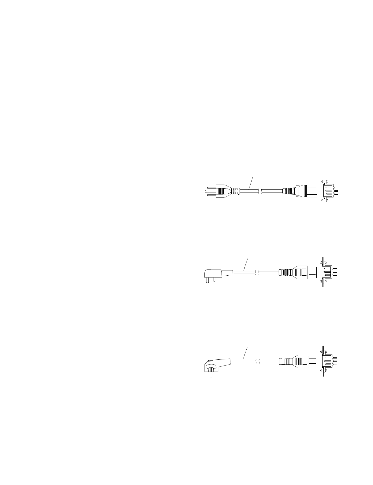
1-2-3. Power Cord
w
The power cords are not supplied with DVS-7150 and the
control panel. Be sure to use the power cords that are
applicable to the places in the world.
To avoid a fire or an electric shock, be sure to use the
designated power cord. And do not damage to the power
cord.
For the customer in the U.S.A. and Canada
Required Parts
1 Power Cord, 125 V 10 A (2.4 m) : 1-557-377-11
1
For the customer in the United Kingdom
Required Parts
DK-2401 (EK)
1 Power Cord, 250 V 10 A (2.4 m)
AC inlet
1-2-2. Power Specifications
Power requirements : 100 to 240 V AC ± 10%
50/60 Hz
Current consumption
DVS-7150 : 4 to 2 A
BKDS-7017 : 1.0 A (max.)
m
As the inrush current at turn-on is the maximum 20 A, the
capacity of the AC power must be commensurate in it with
the inrush current of the maximum 20 A for the processor
and the control panel respectively. If the capacity of the
AC power is not the adequately large, the breaker of the
AC power at the supply side will operate or the unit will
abnormal operate.
1
For the customer in the all European countries
except the United Kingdom
Required Parts
DK-2401 (AE)
1 Power Cord, 250 V 10 A (2.4 m)
1
AC inlet
AC inlet
n
For the customer outside of the area as shown above,
please consult with local Sony’s sale/service office.
DVS-7150E IM
1-1

1-3. Connectors
1-3. Connectors
When connecting cables to various connectors on the rear
panel at the time of installing, connecting or servicing,
connect the following connectors or their equivalents.
1. DVS-7150
Connector function name Connector parts No. and
on rear panel name of cable
(*2)
(* 2)
(*2)
(* 2)
(* 2)
(*2)
(* 2)
(* 2)
(* 2)
(* 2)
D-sub 9-pin, Male
Connector 9-pin, Male
1-560-651-00
(*1)
Junction Shell 9-pin
1-561-749-00
D-sub 25-pin, Male
Connector 25-pin, Male
1-560-904-11
(*1)
Junction Shell 25-pin
1-563-377-11
Main Power Supply Cable
(For the details of the cable,
refer to Section 1-2-3.)
PANEL 1
DME 1 to 2
SERIAL TALLY
TERMINAL
EDITOR-A/REMOTE 1
EDITOR-B/REMOTE 2
PANEL 2/REMOTE 3
MATRIX/REMOTE 4
GPI
PRIMARY INPUTS 1 to 24 BNC Coaxial Connector Plug
CRK INPUT 1 to 2
REF INPUT
REF OUTPUT
AUX BUS OUTPUTS 1 to 6
ME OUTPUTS 1 to 2
PGM OUTPUTS 1 to 4
PVW OUTPUTS 1 to 2
EDIT PVW OUTPUT
AC IN
2. BKDS-7017
Connector function name Connector parts No. and
on rear panel name of cable
(*2)
(*2)
(*2)
(*2)
D-sub 9-pin, Male
Connector 9-pin, Male
1-560-651-00
(*1)
Junction Shell 9-pin
SWITCHER
DME
TERMINAL 1 to 2
REMOTE 1 to 4
1-561-749-00
OPTION PANEL
(*2)
BVS Cable
1-574-993-11
(*2)
AC IN
Main Power Supply Cable
(For the details of the cable,
refer to Section 1-2-3.)
(*1):The following solderless contact must be used for the plug.
AWG #18 to #22:1-566-493-00
AWG #22 to #24:1-564-774-00
AWG #24 to #30:1-564-775-00
(*2):For the customers in europe
When connecting the cables to the following connectors, attach the two
ferrite cores that are packed with each model to the two connectors at
the both sides of the cable.
1-2
DVS-7150E IM
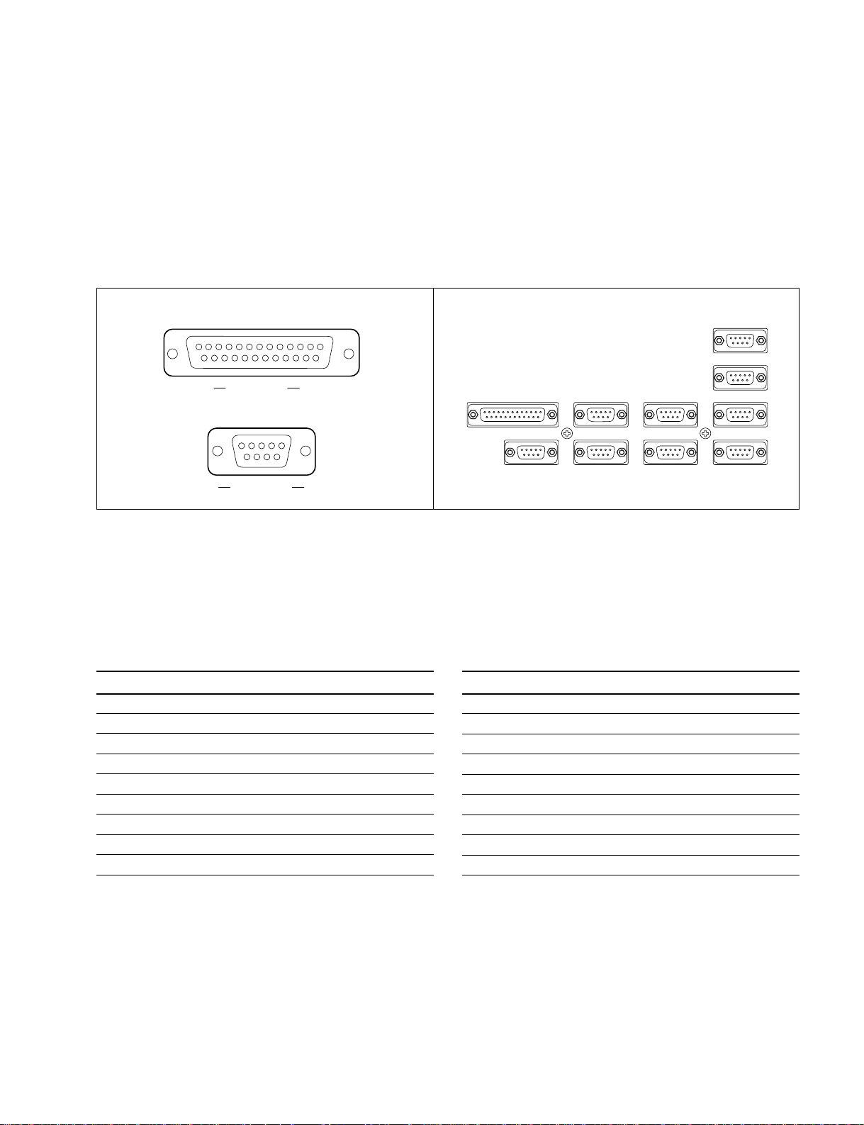
1-4. Input and Output Signals of
Connectors
The input and output signals of the connectors on the rear
panel are specified in the following table. And refer to the
following illustration for the pin positions of the connectors.
1-4-1. DVS-7150
1-4. Input and Output Signals of Connectors
[D-SUB 25 PIN • FEMALE]
13
25
1
14
EXT VIEW
[D-SUB 9 PIN • FEMALE]
5
1
69
EXT VIEW
m
(*1) <CONTROLLER>: Controlling device
(*2) <DEVICE> : Controlled device
PANEL 1 : RS-422A (D-sub 9-pin.Female)
<DEVICE>
Pin No. Signal Name Function
1 GND Frame ground
2 TX-A Transmitted data (_)
3 RX-B Received data (+)
4 GND Common ground
5 FIELD (+) Field signal output (+)
6 GND Common ground
7 TX-B Transmitted data (+)
8 RX-A Received data (_)
9 FIELD (_) Field signal output (_)
(*2)
from Control panel BKDS-7017
PANEL1
9
DME1
9
SERIAL TALLY
9
9
DME2
9
MATRIX /REMOTE4
9
25
GPI
PANEL2 /REMOTE3
9
TERMINAL
9
EDITOR-B /REMOTE2 EDITOR-A /REMOTE1
9
Rear panel
PANEL 2/REMOTE 3 : RS-422A (D-sub 9-pin.Female)
<DEVICE>
(* 2)
from Control panel
Pin No. Signal Name Function
1 GND Frame ground
2 TX-A Transmitted data (_)
3 RX-B Received data (+)
4 GND Common ground
5 VD-B Transmited VD signal (+)
6 GND Common ground
7 TX-B Transmitted data (+)
8 RX-A Received data (_)
9 VD-A Transmited VD signal (_)
(*3):Control Panel BKDS-2010 etc. (PANEL 2)
Keyer Remote Panel BKDS-7060 etc. (REMOTE 3)
(* 3)
DVS-7150E IM
1-3

1-4. Input and Output Signals of Connectors
SERIAL TALLY : RS-422A (D-sub 9-pin.Female)
<CONTROLLER>
(*1)
n
For the SERIAL TALLY connector, refer to the Protocol
Manual of DVS-8000 Series.
Pin No. Signal Name Function
1 FG Frame ground
2 RX-A Received data (_)
3 TX-B Transmitted data (+)
4 GND Common ground
5 __
6 GND Common ground
7 RX-B Received data (+)
8 TX-A Transmitted data (_)
9 FG Frame Ground
DME 1, 2 : RS-422A (D-sub 9-pin.Female)
<DEVICE>
(*2)
from Digital multi effects DME-3000/7000
etc.
Pin No. Signal Name Function
1 FG Frame ground
2 TX-A Transmitted data (_)
3 RX-B Received data (+)
4 GND Common ground
5 __
6 GND Common ground
7 TX-B Transmitted data (+)
8 RX-A Received data (_)
9 FG Frame Ground
EDITOR-A/REMOTE 1 : RS-422A (D-sub 9-pin.Female)
<DEVICE>
Pin No. Signal Name Function
1 FG Frame ground
2 EDT A TX-A Transmitted data (_)
3 EDT A RX-B Received data (+)
4 GND Common ground
5 __
6 GND Common ground
7 EDT A TX-B Transmitted data (+)
8 EDT A RX-A Received data (_)
9 FG Frame Ground
(*5):Editing control Unit BVE-9100 etc. (EDITOR A)
(*2)
from Editor
(*5)
EDITOR-B/REMOTE 2 : RS-422A (D-sub 9-pin.Female)
<DEVICE>
Pin No. Signal Name Function
1 FG Frame ground
2 TX-A Transmitted data (_)
3 RX-B Received data (+)
4 GND Common ground
5 __
6 GND Common ground
7 TX-B Transmitted data (+)
8 RX-A Received data (_)
9 FG Frame Ground
(*6):Editing control Unit BVE-9100 etc. (EDITOR B)
(*2)
from Editor
(*6)
TERMINAL : RS-232C (D-sub 9-pin.Female)
to Terminal
MATRIX/REMOTE 4
<CONTROLLER>
Pin No. Signal Name Function
1 FG Frame ground
2 RX-A Received data (_)
3 TX-B Transmitted data (+)
4 GND Common ground
5 __
6 GND Common ground
7 RX-B Received data (+)
8 TX-A Transmitted data (_)
9 FG Frame Ground
(*4)
: RS-422A (D-sub 9-pin.Female)
(*1)
to Routing switcher
1-4
Pin No. Signal Name Function
1 DCD Data Carrier detect
2 RXD Received data
3 TXD Transmitted data
4 DTR Data terminal ready
5 SG Signal ground
6 DSR Data set ready
7 RTS Request to send
8 CTS Clear to send
9 __
(*7) :Pins 1, 4 and 6 are short-circuited each other on the CN-1751 board.
(*7)
(*7)
(*7)
DVS-7150E IM
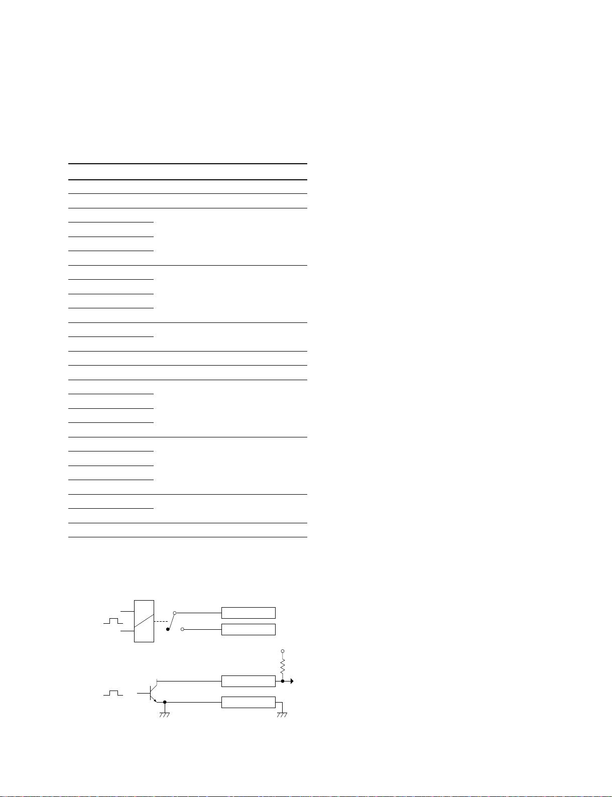
GPI : (D-sub 25-pin.Female)
INPUT x 8, TTL
OUTPUT x 4, relay contact 30 V 0.1 A
(resistance load)
OUTPUT x 4, open collector 30 V rated voltage
GPI timing : Refer to User’s Guide
Pin No. Signal Name Function
1 GND Ground
2 GND Ground
3 GPI IN 2
4 GPI IN 4
5 GPI IN 6
6 GPI IN 8
7 GPI OUT 1B
8 GPI OUT 2B
9 GPI OUT 3B
10 GPI OUT 4B
11 GPI OUT 6
12 GPI OUT 8
13 GPI OUT COM Ground for open collector output
14 GND Ground
15 GPI IN 1
16 GPI IN 3
17 GPI IN 5
18 GPI IN 7
19 GPI OUT 1A
20 GPI OUT 2A
21 GPI OUT 3A
22 GPI OUT 4A
23 GPI OUT 5
24 GPI OUT 7
25 GPI OUT COM Ground for open collector output
General-purpose input
General-purpose relay output (B)
General-purpose open collector output
General-purpose input
General-purpose relay output (A)
General-purpose open collector output
1-4. Input and Output Signals of Connectors
(*8)
(*9)
(*8)
(*9)
n
A and B of same number constitute a pair of relay contacts.
(*8) : <Relay>
GPI OUT x B
GPI OUT x A
x;1-4
(*9) : <Open collector output>
GPI OUT 5-8
GPI OUT COM
DVS-7150E IM
+V
1-5

1-4. Input and Output Signals of Connectors
1-4-2. BKDS-7017
[D-SUB 25 PIN • FEMALE]
13
25
EXT VIEW
[D-SUB 9 PIN • FEMALE]
5
69
EXT VIEW
m
(*1) <CONTROLLER> : Controlling device
1. Main Panel
SWITCHER : RS-422A (D-sub 9-pin.Female)
<CONTROLLER>
(*1)
to Processor DVS-7150
1
14
1
SWITCHER DME TERMINAL1 TERMINAL2
1
5
69
OPTION PANEL REMOTE1 REMOTE2 REMOTE3 REMOTE4
13
25
1
14
1
5
69
1
5
69
1
5
69
1
5
5
5
69
1
5
69
Rear panel
REMOTE 1 to 4
<CONTROLLER>
(*2)
: RS-422A (D-sub 9-pin.Female)
(*1)
to External Device
1
69
1
69
Pin No. Signal Name Function
1 FG Frame ground
2 RX-A Received data (_)
3 TX-B Transmitted data (+)
4 GND Common ground
5 FIELD (+) Field signal input (+)
6 GND Common ground
7 RX-B Received data (+)
8 TX-A Transmitted data (_)
9 FIELD (_) Field signal input (_)
DME : RS-422A (D-sub 9-pin.Female)
<CONTROLLER>
(*1)
to Digital multi effects DME-3000/
7000 etc.
Pin No. Signal Name Function
1 FG Frame ground
2 RX-A Received data (_)
3 TX-B Transmitted data (+)
4 GND Common ground
5 _ NC
6 GND Common ground
7 RX-B Received data (+)
8 TX-A Transmitted data (_)
9 __
Pin No. Signal Name Function
1 FG Frame ground
2 RX-A Received data (_)
3 TX-B Transmitted data (+)
4 GND Common ground
5 __
6 GND Common ground
7 RX-B Received data (+)
8 TX-A Transmitted data (_)
9 __
(*2) :BKDS-7001 (Option : IF-523 board) is in need of using the REMOTE
from 1 to 4.
TERMINAL 1, 2 : RS-232C (D-sub 9-pin.Female)
to Terminal
Pin No. Signal Name Function
1 DCD Received line signal detector signal
2 RX Received data
3 TX Transmitted data
4 DTR Data terminal ready signal
5 GND Signal ground
6 DSR Data set ready signal
7 RTS Request to send signal
8 CTS Clear to send signal
9 __
(*3) :Pins 1, 4 and 6 are short-circuited each other on the CN-1149 board.
(*4):Pins 7 and 8 are short-circuitede each other on the CN-1149 board.
(*3)
(* 3)
(*4)
(* 4)
(*3)
1-6
DVS-7150E IM

OPTION PANEL : (D-sub 25-pin.Female)
to Adaptor box (BKDS-7075)
Pin No. Signal Name Function
1 GND Ground
2 +12 V Power supply +12 V
3 SCLK Serial clock for switch read and LED
light
4 GND Ground
5 WDT LED light data
6 IWLD Control signal for switch read and LED
light
7 GND Ground
8 TCLK Serial clock for character display
9 TWDT Indicate data for character display
10 GND Ground
11 TBLANK Disable signal for character display
12 GND Ground
13 GND Ground
14 +12 V Power supply +12 V
15 +12 V Power supply +12 V
16 BLANK LED light disable signal
17 GND Ground
18 SEQ Control signal for switch read and LED
light
19 RDT Switch read data
20 GND Ground
21 TSEQ Control signal for character display
22 TQCLK Control signal for character display
23 +12 V Power supply +12 V
24 +12 V Power supply +12 V
25 GND Ground
1-4. Input and Output Signals of Connectors
DVS-7150E IM
1-7
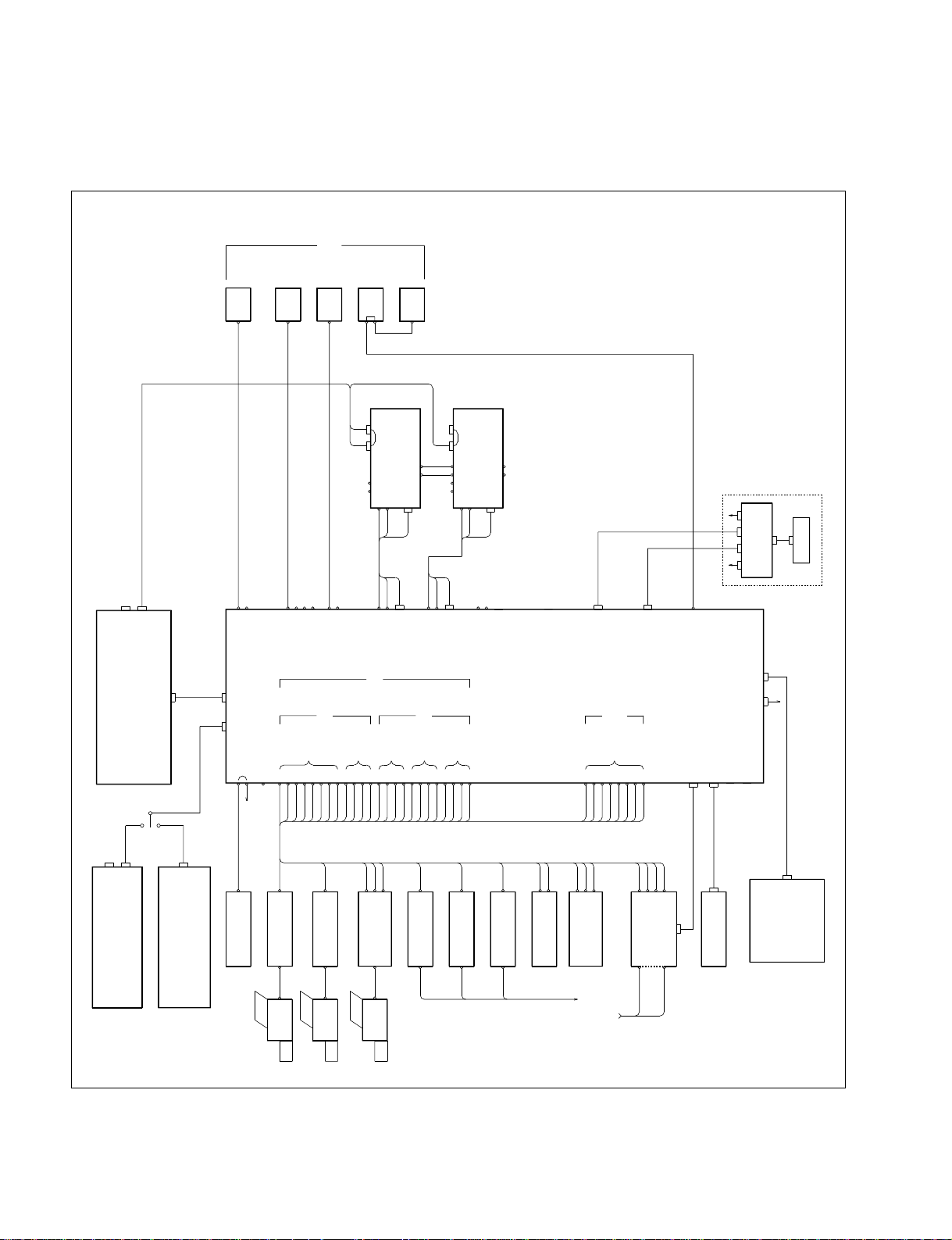
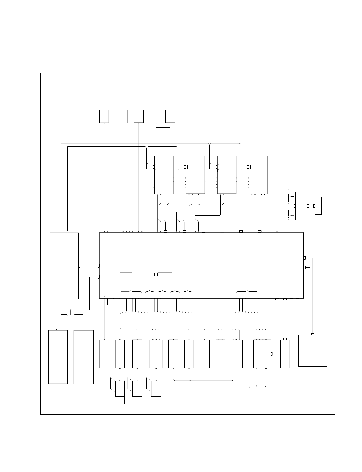
1-5. Example of System Connection
1234567891011121314151617181920212223
24
Y1U1V1S1Y2U2V2
S2
TERMINAL
MATRIX/REMOTE 4
x4
ROUTER
x4
SUPER V/K
x4
DME V/K
x4
VTR
REF OUT
REF IN
CAMERA
x8
SW'ER
K
V
DME PANEL
DME-7000
BKDS-7016/7016L/7017
INPUTS
COMPONENT
ANALOG
CRK IN
INPUTS
DIGITAL
INPUTS
DIGITAL
IN
PRIMARY
CONTROL PANEL
KEYER REMOTE
BKDS-7060
CONTROL
OUT1
CONTROL
OUT2
REMOTE 3
PANEL 2
SUB PANEL
BKDS-2010
SW'ER
SG
CCU
DCU
DCU
DVW-500
Y
U
V
REC
SOURCE
LINE IN
CG
BVW-75
BVW-75D
DVR-2000
V
K
YUV
ROUTER
DVS-V6464B
PC
TALLY
INTERFACE
UNIT
BKDS-7700
GPI
SERIAL
TALLY
D1 LIVE SW'ER
DVS-7150
EDIT PVW
EDITOR-B
/REMOTE 2
EDITOR-A
/REMOTE 1
AUX3
AUX4
DME2
AUX5
AUX6
AUX1
AUX2
DME1
PGM1
PGM2
PVW1
PVW2
PGM3
PGM4
ME OUT1
ME OUT2
PANEL 2
/REMOTE 3 1
PANEL
SWITCHER
MAIN PANEL
REMOTE2
DME
DME2
VKVKZ
SW'ER PANEL
VKZ
SW'ER
K
V
DME PANEL
DME-7000
DME1
VK
SW'ER PANEL
VKZ
MONITOR
VE
WFM
PGM
PVW
ME1
BVE-9100
EDITOR
DMEVTR AB
KEY BOARD
1-5. Example of System Connection
1. D1 LIVE SWITCHER SYSTEM
1-8
DVS-7150E IM
2. D2 LIVE SWITCHER SYSTEM
1234567891011121314151617181920212223
24
Y1U1V1S1Y2U2V2
S2
TERMINAL
MATRIX/REMOTE 4
x4
ROUTER
x4
SUPER V/K
x4
DME V/K
x4
VTR
REF OUT
REF IN
CAMERA
x8
DME PANEL
V
K
SW'ER
SW'ER
K
V
DME PANEL
DME-7000
DME-7000
BKDS-7016/7016L/7017
INPUTS
COMPONENT
ANALOG
CRK IN
INPUTS
DIGITAL
COMPOSITE
ANALOG
IN
PRIMARY
INPUTS
CONTROL PANEL
KEYER REMOTE
BKDS-7060
CONTROL
OUT1
CONTROL
OUT2
REMOTE 3
PANEL 2
SUB PANEL
BKDS-2010
SW'ER
SG
CCU
CCU
CCU
DVR-28
Y
U
V
REC
SOURCE
LINE IN
CG
BVW-75
DVR-20
BVW-D265
V
K
YUV
ROUTER
DVS-V6464B
PC
TALLY
INTERFACE
UNIT
BKDS-7700
GPI
SERIAL
TALLY
D2 LIVE SW'ER
DVS-7150
EDIT PVW
EDITOR-B
/REMOTE 2
EDITOR-A
/REMOTE 1
AUX3
AUX4
DME2
AUX5
AUX6
AUX1
AUX2
DME1
PGM1
PGM2
PVW1
PVW2
PGM3
PGM4
ME OUT1
ME OUT2
PANEL 2
/REMOTE 3 1
PANEL
SWITCHER
MAIN PANEL
REMOTE2
DME
DME2
VKVKZ
SW'ER PANEL
SW'ER PANEL
VKZ
SW'ER
K
V
DME PANEL
DME-7000
DME3
VKVKZ
VKZ
SW'ER
K
V
DME PANEL
DME-7000
DME1
VK
SW'ER PANEL
VKZ
KZKVV
DME4
MONITOR
VE
WFM
PGM
PVW
ME1
BVE-9100
EDITOR
DMEVTR AB
KEY BOARD
1-5. Example of System Connection
DVS-7150E IM
1-9

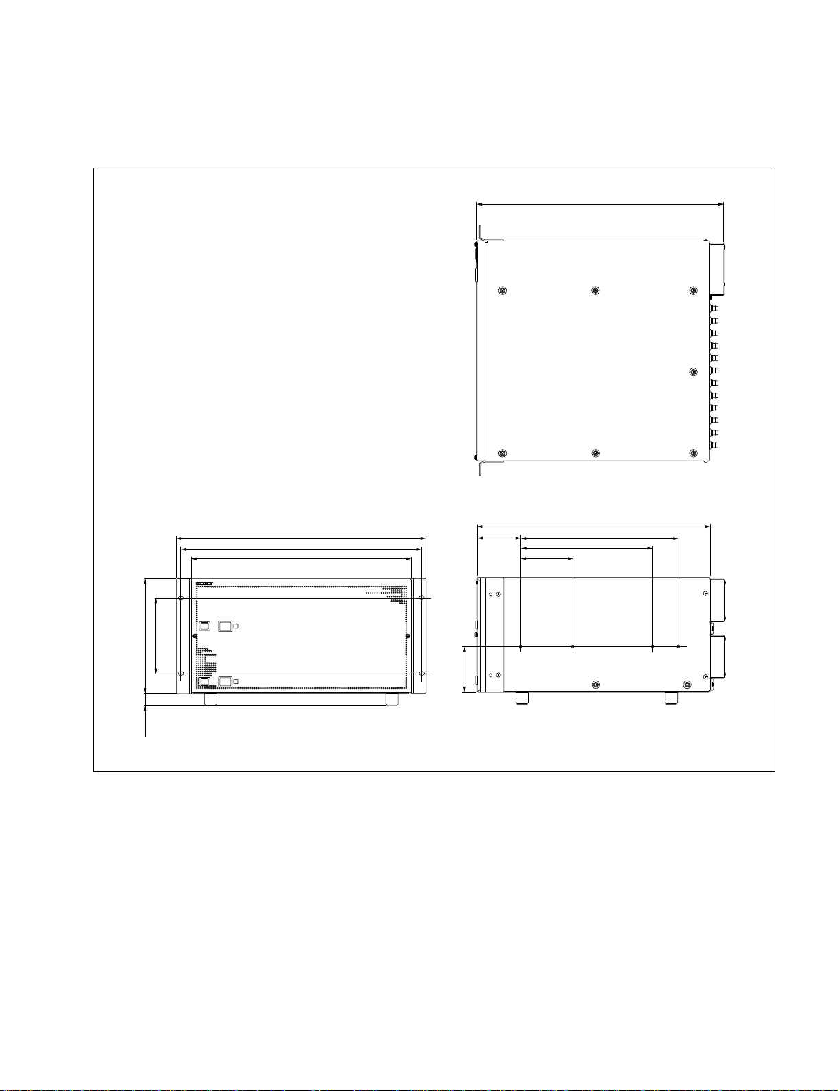
2-1. External Dimensions
Section 2
Installation of DVS-7150
475
146
221(5UNIT)
23.5
A
B
482
465
424
(Front view)
DIGITAL VIDEO SWITCHER DVS-7150
88.2
83.7
(Top view)
450
304.8
101.6
254
(Right side view)
Unit : mm
DVS-7150E IM
2-1

2-2. Rack Mounting
2-2. Rack Mounting
DVS-7150 can be mounted in a 19-inch standard rack. Be sure to use the optional rack mount rail RMM-
30.
< Required Parts >
. Rack mount rail (RMM-30)
Rails with bracket : 2 pcs
Screw (B5 x 8) : 8 pcs
. Screw (BVTT4 x 8)
. Screw for rack mounting (RK5 x 16) : 4 pcs
. Ornamental washer for rack mounting : 4 pcs
(Sony part number : 2-297-913-01)
(*1) : DVS-7150 is supplied with the eight screws. Use two of them for the spare parts.
c
(1) If DVS-7150 is mounted in a 19-inch standard rack, it is recommended to install a ventilation fan to
prevent a temperature rise in the rack. Make sure that all the units in the rack should be operated
within the temperature range of 10 dC to 35 dC.
(2) Be sure to use the recommended rail when rack mounting. The unit cannot be installed completely to
a rack by rack angles alone.
(3) It is recommended to fix the rack to the floor with bolts. When the unit is pulled out from the rack,
this will prevent its fall.
(4) An installation manual is supplied with the rack mount rail RMM-30. However follow the instruc-
tions in this manual. Because the rack mounting procedures of DVS-7150 differ somewhat from the
procedures explained in RMM-30 installation manual.
(5) Be sure to mount in the rack with two-person or more.
(*1)
: 6 pcs
2-2
DVS-7150E IM
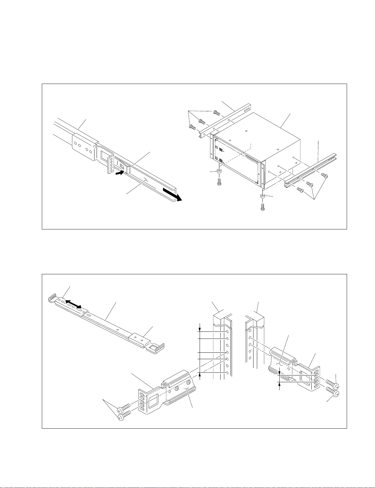
Procedures
(1) Pull out the inner member while pressing the stopper of the rack mount rail RMM-30. (Fig. 1)
(2) Secure the inner member to the unit by the six screws (BVTT 4 x 8) supplied with DVS-7150.
Remove the feet of the unit as required. (Fig. 2)
Inner menber
BVTT4 x 8
Outer menber
Stopper
Feet
DVS-7150
2-2. Rack Mounting
Inner menber
Inner menber
(Fig. 1) (Fig. 2)
Feet
(3) Loosen the screws secured the rear bracket to the outer member. Adjust the position of the rear
bracket in line with the rack depth. (Fig. 3)
(4) Temporarily secure the front and rear brackets to the outside of the rack by the eight screws (B5 x 8)
supplied with RMM-30. (Fig. 4)
Rear braket
Outer member
(Fig. 3)
Rack (Left)
Front bracket
12.7
31.75
12.7
31.75
Front bracket
Rack (Right)
Outer member
12.7
BVTT4 x 8
Front bracket
B5 x 8
DVS-7150E IM
B5 x 8
B5 x 8
Outer member
(Fig. 4)
2-3
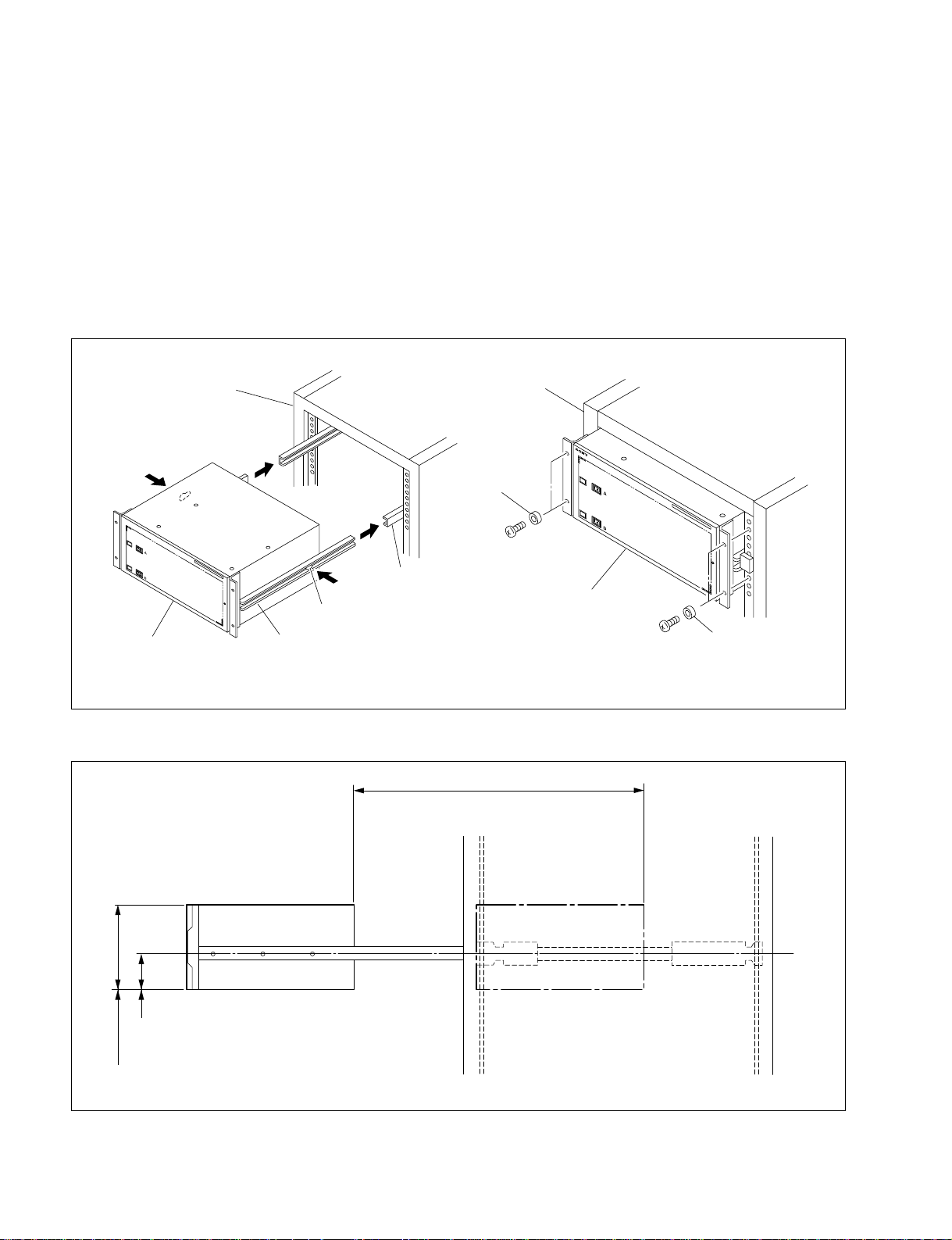
2-2. Rack Mounting
(5) For installing the unit in the rack, press the inner members fully to the outer members while pressing
the stoppers of the inner members. (Fig. 5)
(6) After confirming that the unit can be moved smoothly, tighten the screws (B5 x 8) secured tempo-
rarily in the step (4).
n
When securing the front brackets to the rack by screws, pull out the unit about 20 cm (8 inches) from
the rack, and fasten the screws of the front brackets to the rack.
(7) After installing the unit in the rack, secure the unit to the rack by the prepared four screws (RK5 x
16) and four ornamental washers. (Fig. 6)
Rack
DVS-7150
RK5 x 16
DVS-7150
Rack
Ornamental washer
RK5 x 16
Outer menber
Stopper
Inner member
(Fig. 5) (Fig. 6)
. When DVS-7150 is mounted in a rack, the maximum traveling distance is illustrated below.
581
Maximum travelling distance
Ornamental washer
221.2
88.6
Distance to the center of the slide rail
Height of the unit mounted in a Rack
2-4
Unit : mm
DVS-7150E IM

3-1. External Dimensions
Main Panel
BKDS-7017
Section 3
Installation of Control Panel
14
496
30
AUX
M/E
K
A
B
PGM/PST
DSK
PGM
PST
AUX DELEGATION
760
96
96
96
96
5
5
1
MANUAL
INSTRUCTION
SEE
96
5
1
TERMINAL 2
5
1
1
1
REMOTE 2
REMOTE 3 REMOTE 4
96
96
5
5
1
1
1
DME
TERMINAL 1
25 14
5
13
1
OPTION PANEL
REMOTE 1
96
5
SWITCHER
850
TOP MENU
UTILITY
30
14
24
11076.8
10
15
51
385
DOWNSTREAM KEYER
DVS-7150system
3015
DVS-7150E IM
Unit : mm
3-1
3-1. External Dimensions
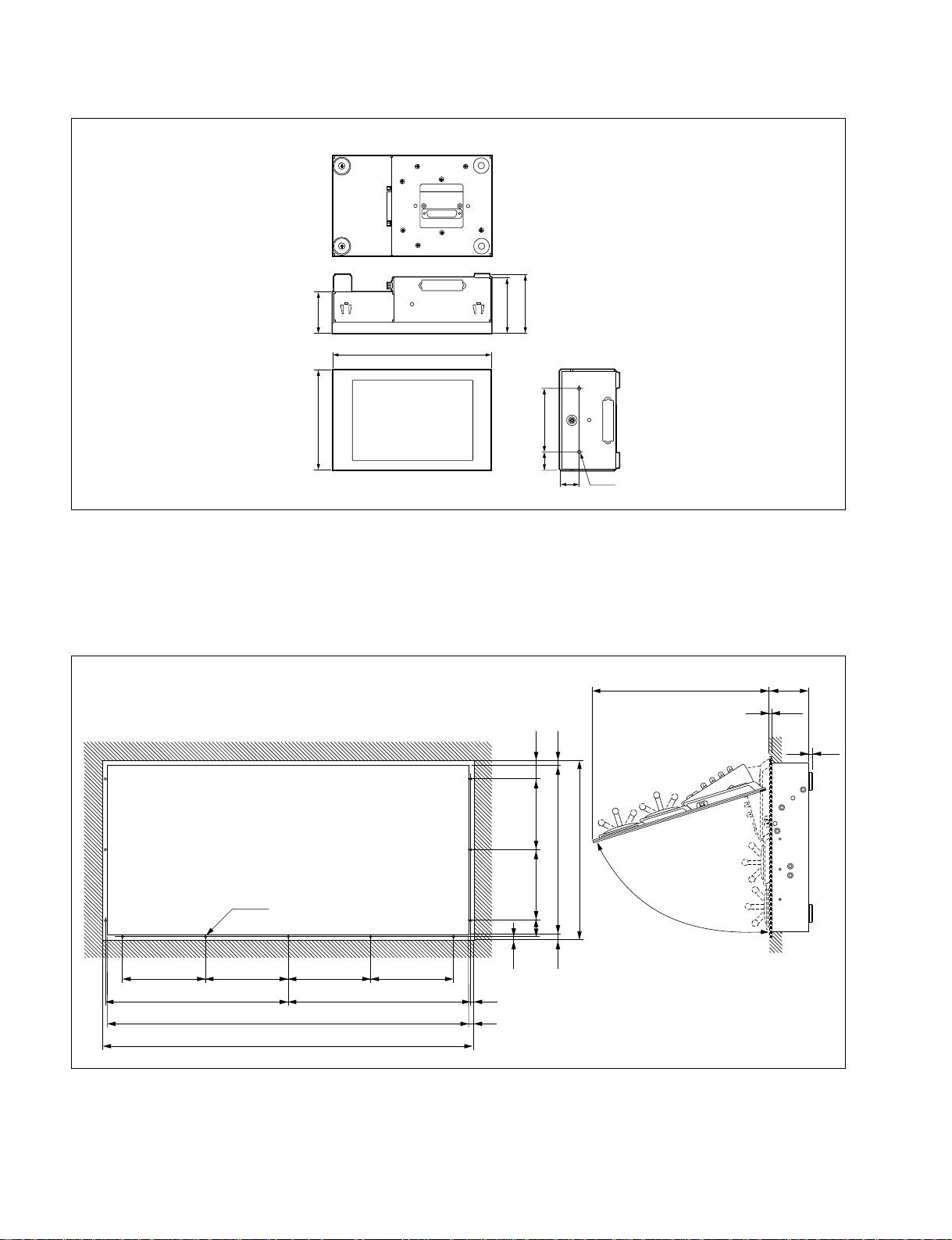
3-2. Installation Space to Console
BKDS-7075
55
212
74
78.5
132
84
24
26
2-M4
3-2. Installation Space to Console
Control panel can be installed in the console by drilling holes in the console in the locations specified
below.
BKDS-7017
(52)
15
470
500
483 110
Unit : mm
7.2
10
3-2
11-M4
185 185
418
185 185
824
854
418 9
15
198 198
43
9
15
Approx.75d
Unit : mm
DVS-7150E IM
Loading...