


LC-39LE650V
SHARP LC-39LE650V, LC-39LE650RU, LC-39LE650E, LC-39LE651E, LC-39LE651K Service Manual
...
LC-39/50LE650
160mm
125mm
100mm
80mm
63mm
50mm
A-data-1
Corporate Trademark
LC-39/50LE651
LC-39/50LE652
SERVICE MANUAL
S1stLC39LE650
Issued: 14
th
June 2013
1st Edition
Wi-Fi & 3D Ready / DVB-T / T2 / C / S / S2 PAL B/G / SECAM B/G, D/K, L/L’ SYSTEM COLOUR TELEVISION
LED LCD COLOUR TELEVISION
MODELS
LC-39LE650E/RU/V
LC-39LE651E/K/RU/V
LC-39LE652E/RU/V
LC-50LE650E/RU/V
LC-50LE651E/K/RU/V
LC-50LE652E/RU/V
In the interests of user safety (required by safety
regulations in some countries) the set should be restored to its original condition and only parts identical
to those speci ed should be used.
CONTENTS
ELECTRICAL SPECIFICATIONS ........................................................................................ 2
IMPORTANT SERVICE SAFETY PRECAUTIONS ......................................................................... 3
OPERATION MANUAL .................................................................................................................... 6
DIMENSIONS .................................................................................................................... 22
REMOVING OF MAJOR PARTS ..................................................................................................... 23
SERVICE ADJUSTMENTS ............................................................................................................. 33
PUBLIC MODE .................................................................................................................................... 44
SOFTWARE UPGRADING ............................................................................................................. 47
MAJOR ICs INFORMATION ..................................................................................................... 48
BLOCK DIAGRAMS ..................................................................................................................... 63
SCHEMATIC DIAGRAMS ....................................................................................................... 66
PRINTED WIRING BOARDS ......................................................................................................... 114
REPLACEMENT PARTS LIST ....................................................................................................... 121
CABINET AND MECHANICAL PARTS ............................................................................................ 141
PACKING OF THE SET ....................................................................................................................... 145
SHARP CORPORATION
1
This document has been published to
be used for after sales service only.
The contents are subject to chage without notice.

LC-39/50LE650
Appendix
LC-39/50LE651
LC-39/50LE652
Specifications
ELECTRICAL SPECIFICATIONS
Item
LCD Panel (
Resolution 6.220.800 dots (1.920 x 1.080 pixels)
Video Colour System PAL/SECAM/NTSC 3.58/NTSC 4.43/PAL 60
TV
Functions
Viewing angles H: 176°, V: 176°
Audio Ampli er 15 W + 15 W (Music power)
Speaker (96 mm x 30mm) x 2
Terminals
OSD language
Power Requirement AC 220–240 V, 50 Hz
Power Consumption (IEC62087 Method) 99W
Weight 10.7Kg
Operating Temperature 0 °C to +40 °C
LED TV) 39” BLACK TFT 50” BLACK TFT 60” BLACK TFT
TV Standard Analogue CCIR (B/G, I, D/K, L/L’)
Digital DVB-T (2K/8K OFDM)(H.264), DVB-C, DVB-C2 (L*654 only), DVB-T2(L*651/654
Receiving
Channel
TV-Tuning System Auto Preset 999 ch: non-Nordic / 9999 ch: Nordic (ATV: 99 ch), Auto Label, Auto Sort
STEREO / BILINGUAL NICAM/A2
TV Antenna VHF/UHF UHF/VHF 75 Ω Din type (Analogue & Digital)
SERVICE Ø 3.5 mm jack
SCART SCART (AV input, RGB input, TV output, Y/C input)
PC INPUT VGA (D-Sub 15pin), Ø 3.5 mm jack (shared with HDMI)
COMPONENTS COMPONENT IN: Y/PB(CB)/PR(CR), RCA (AUDIO R/L)
HDMI1 HDMI, Ø 3.5 mm jack (shared with PC INPUT), ARC, 3D.
HDMI2 HDMI, Ø 3.5 mm jack (shared with PC INPUT), 3D.
HDMI3 HDMI, Ø 3.5 mm jack (shared with PC INPUT), 3D.
HDMI4 HDMI, Ø 3.5 mm jack (shared with PC INPUT), 3D.
USB 1 USB 2.0 HOST (A Type)
USB 2 USB 2.0 HOST (A type)
USB 3 (WIFI) USB 2.0 HOST (A type) (Wi-Fi use only)
ETHERNET (10/100) Network connector
AV RCA connector (AV input)
S/PDIF OUT RCA S/PDIF digital audio output.
C. I. (Common Interface) EN50221, R206001, CI+ speci cation
Headphones Ø 3.5 mm jack (Audio output)
VHF/UHF E2–E69 ch, F2–F10 ch, I21–I69 ch, IR A–IR J ch (Digital: IR A ch–E69 ch)
CATV Hyper-band, S1–S41 ch
Satellite (652/654
series only)
39” LCD COLOUR TV,
Models:
LC-39LE650E/RU/V
LC-39LE651
LC-39LE652E/RU/V
LC-39LE654E/RU/V
LC-39LU651E
LC-39LM652E/V
LC-39LK652E
LC-39LX652E
only), DVB-S/S2 (L*652/654 only)
75 Ω F type (DVB-S/S2)
Czech, Danish, Dutch, English, Estonian, Finnish, French, German, Greek, Hungarian,
Italian, Latvian, Lithuanian, Norwegian, Polish, Portuguese, Russian, Slovak, Slovene,
Spanish, Swedish, Turkish, Ukrainian, Byelorussian, Romanian, Croatian, Serbian.
(0.24W Stby)
13.3 Kg (With stand)
E/K/RU/V
(Without stand)
50” LCD COLOUR TV,
Models:
LC-50LE650E/RU/V
LC-50LE651
LC-50LE652E/RU/V
LC-50LE654E/RU/V
LC-50LU651E
LC-50LM652E/V
LC-50LK652E
LC-50LX652E
121W
(0.24W Stby)
16.7Kg
20.1Kg (With stand)
E/K/RU/V
(Without stand)
60” LCD COLOUR TV,
Models:
LC-60LE650E/RU
LC-60LE651
LC-60LE652E/RU
LC-60LE654E/RU
LC-60LU651E
LC-60LM652E
LC-60LK652E
LC-60LX652E
175W
(0.24W Stby)
24.3Kg
29.6 Kg (With stand)
E/K/RU
(Without stand)
2
LC-39/50LE650
LC-39/50LE651
LC-39/50LE652
IMPORTANT SERVICE SAFETY PRECAUTION
Service work should be performed only by qualied service technicians who are thoroughly familiar with all
safety checks and the servicing guidelines which follow:
WARNING
1. For continued safety, no modication of any circuit should be attempted.
2. Disconnect AC power before servicing.
CAUTION: FOR CONTINUED PROTECTION AGAINST A RISK OF
FIRE REPLACE ONLY WITH SAME TYPE F101 (T4 AH / 250V)
BEFORE RETURNING THE RECEIVER (Fire & Shock Hazard)
Before returning the receiver to the user, perform the following safety checks:
1. Inspect all lead dress to make certain that leads are not pinched, and check that hardware is not lodged between the
chassis and other metal parts in the receiver.
2. Inspect all protective devices such as non-metallic control knobs, insulation materials, cabinet backs, adjustment and
compartment covers or shields, isolation resistor-capacitor networks, mechanical insulators, etc.
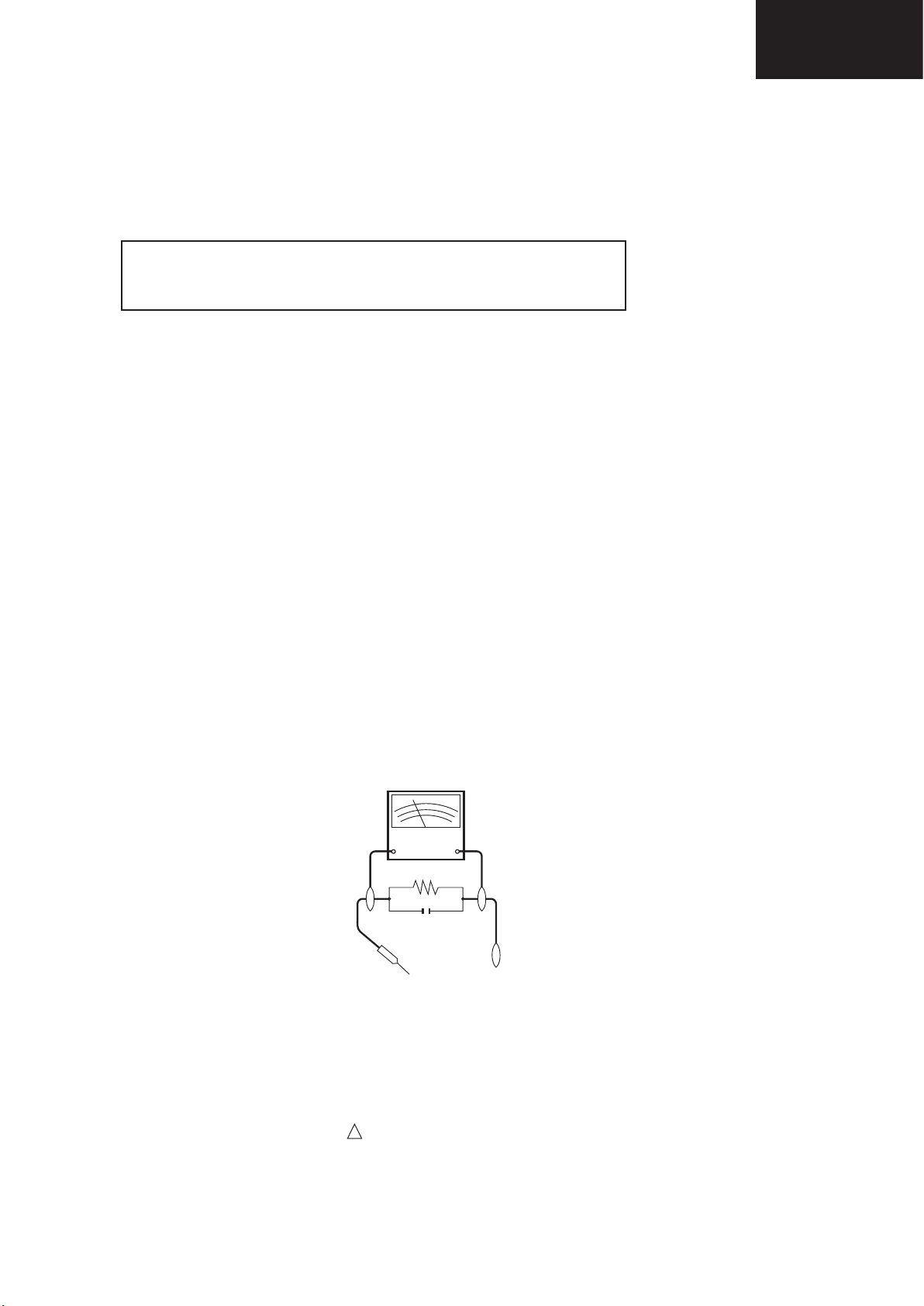
3. To be sure that no shock hazard exists, check for leakage current in the following manner.
• Plug the AC cord directly into a 220~240 volt AC outlet. (Do not use an isolation transformer for this test).
•Using two clip leads, connect a 1.5k ohm, 10 watt resistor paralleled by a 0.15µF capacitor in series with all exposed metal
cabinet parts and a known earth ground, such as electrical conduit or electrical ground connected to an earth ground.
•A true RMS reading multimeter should be used for this test, especially where the equipment uses a switch mode
power supply which may result in very non-sinusoidal leakage current.
•Connect the resistor connection to all exposed metal parts having a return to the chassis (antenna, metal cabinet,
screw heads, knobs and control shafts, escutcheon, etc.) and measure the AC voltage drop across the resistor.
All checks must be repeated with the AC cord plug connection reversed. (If necessary, a nonpolarized adaptor plug must
be used only for the purpose of completing these checks.)
Any reading of 1.05V peak (this corresponds to 0.7 mA. peak AC.) or more is excessive and indicates a potential shock
hazard which must be corrected before returning the monitor to the owner.
DVM
AC SCALE
1.5k ohm
10W
0.15 µF
TEST PROBE
TO EXPOSED
METAL PARTS
CONNECT TO
KNOWN EARTH
GROUND
SAFETY NOTICE
Many electrical and mechanical parts in LCD television have special safety-related characteristics.
These characteristics are often not evident from visual inspection, nor can protection afforded by them be necessarily
increased by using replacement components rated for higher voltage, wattage, etc.
Replacement parts which have these special safety characteristics are identied in this manual; electrical components
having such features are identied by “ “.
!
For continued protection, replacement parts must be identical to those used in the original circuit.
The use of a substitute replacement parts which do not have the same safety characteristics as the factory recommended
replacement parts shown in this service manual, may create shock, re or other hazards.
3
LC-39/50LE650
L F a
LC-39/50LE651
LC-39/50LE652
PRECAUTIONS FOR USING LEAD-FREE SOLDER
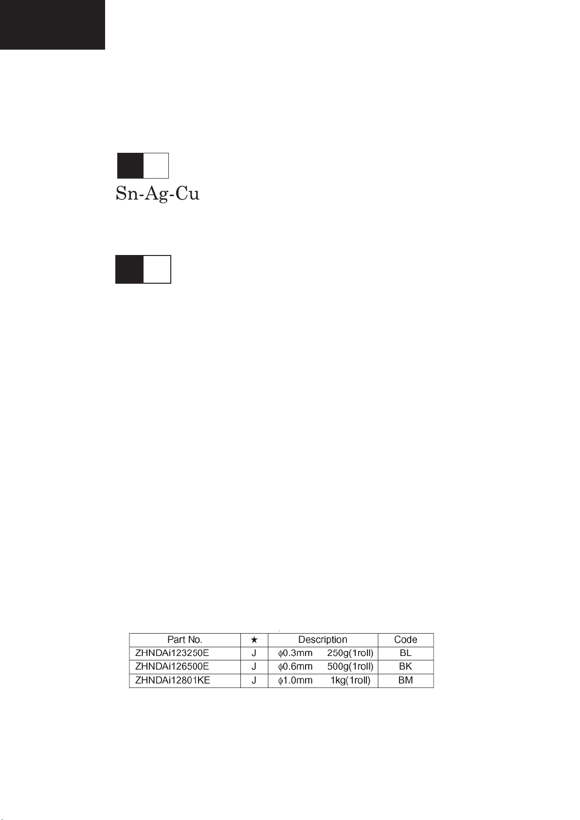
1 Employing lead-free solder
“ALL PWB” of this model employs lead-free solder. The LF symbol indicates lead-free solder, and is attached on the
PWBs and service manuals. The alphabetical character following LF shows the type of lead-free solder.
Example:
Indicates lead-free solder of tin, silver and copper.
L F n
Sn-Ag-Ni
Indicates lead-free solder of tin, silver and nickel.
2 Using lead-free wire solder
When xing the PWB soldered with the lead-free solder, apply lead-free wire solder. Repairing with conventional lead
wire solder may cause damage or accident due to cracks.
As the melting point of lead-free solder (Sn-Ag-Cu) is higher than the lead wire solder by 40°C, we recommend you to
use a dedicated soldering bit, if you are not familiar with how to obtain lead-free wire solder or soldering bit, contact our
service station or service branch in your area.
3 Soldering
As the melting point of lead-free solder (Sn-Ag-Cu) is about 220°C which is higher than the conventional lead solder by
40°C, and as it has poor solder wettability, you may be apt to keep the soldering bit in contact with the PWB for extended
period of time. However, Since the land may be peeled off or the maximum heat-resistance temperature of parts may be
exceeded, remove the bit from the PWB as soon as you conrm the steady soldering condition.
Lead-free solder contains more tin, and the end of the soldering bit may be easily corroded. Make sure to turn on and
off the power of the bit as required.
If a different type of solder stays on the tip of the soldering bit, it is alloyed with lead-free solder. Clean the bit after every
use of it.
When the tip of the soldering bit is blackened during use, le it with steel wool or ne sandpaper.
Be careful when replacing parts with polarity indication on the PWB silk.
Lead-free wire solder for servicing.
4
END OF LIFE DISPOSAL
A. Information on Disposal for Users (private households)
1. In the European Union
Attention: If you want to dispose of this equipment, please do not use the ordinary dust bin!
Used electrical and electronic equipment must be treated separately and in accordance with legislation that requires
proper treatment, recovery and recycling of used electrical and electronic equipment.
Following the implementation by member states, private households within the EU states may return their used
electrical and electronic equipment to designated collection facilities free of charge*. In some countries* your local
retailer may also take back your old product free of charge if you purchase a similar new one.
*) Please contact your local authority for further details.
If your used electrical or electronic equipment has batteries or accumulators, please dispose of these separately
beforehand according to local requirements.
By disposing of this product correctly you will help ensure that the waste undergoes the necessary treatment, recovery
and recycling and thus prevent potential negative effects on the environment and human health which could otherwise
arise due to inappropriate waste handling.
2. In other Countries outside the EU
If you wish to discard this product, please contact your local authorities and ask for the correct method of disposal.
For Switzerland: Used electrical or electronic equipment can be returned free of charge to the dealer, even if you don’t
purchase a new product. Further collection facilities are listed on the homepage of www.swico.ch or www.sens.ch.
B. Information on Disposal for Business Users
1. In the European Union
If the product is used for business purposes and you want to discard it:
Please contact your SHARP dealer who will inform you about the take-back of the product. You might be charged for
the costs arising from take-back and recycling. Small products (and small amounts) might be taken back by your local
collection facilities.
For Spain: Please contact the established collection system or your local authority for take-back of your used
products.
2. In other Countries outside the EU
If you wish to discard of this product, please contact your local authorities and ask for the correct method of disposal.
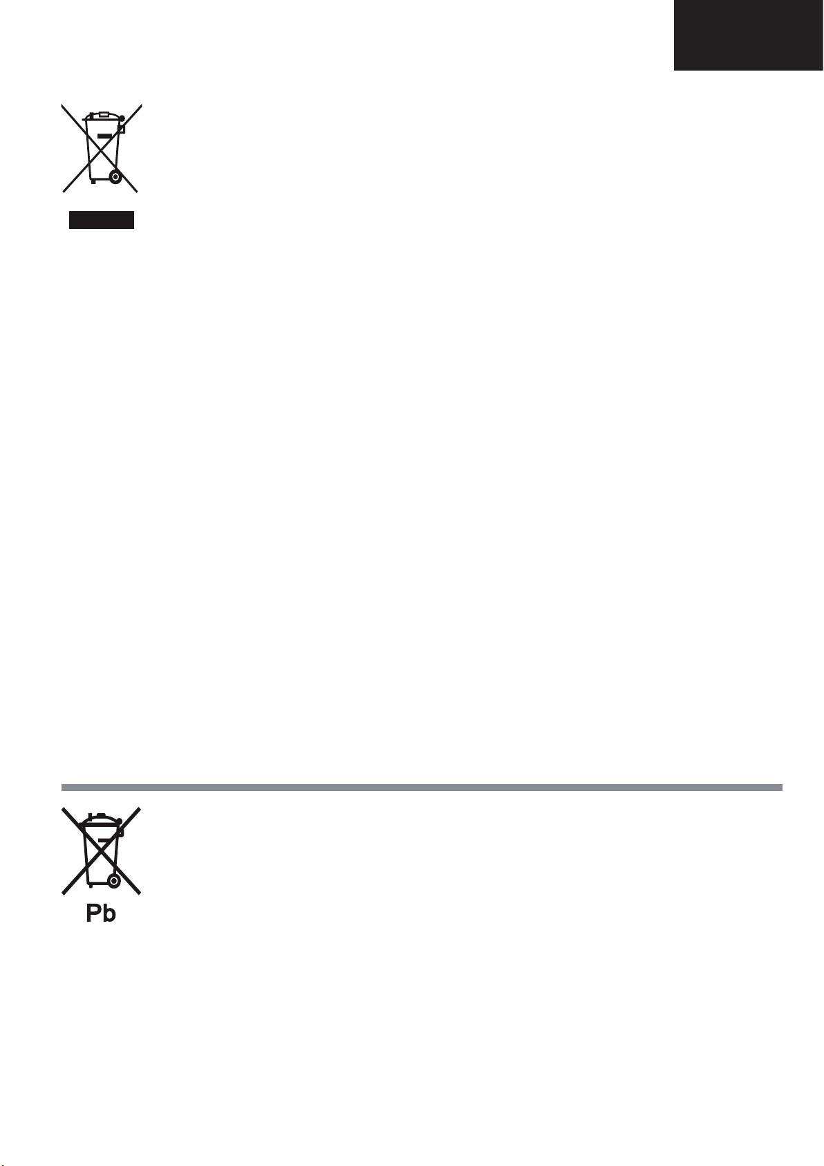
Attention: Your product
is marked with this
symbol. It means that
used electrical and
electronic products
should not be mixed
with general household
waste. There is a
separate collection
system for these
products.
End of life disposal
The battery supplied with this product contains traces of Lead.
For EU: The crossed-out wheeled bin implies that used batteries should not be put to the general household waste!
There is a separate collection system for used batteries, to allow proper treatment and recycling in accordance with
legislation. Please contact your local authority for details on the collection and recycling schemes.
For Switzerland: The used battery is to be returned to the selling point.
For other non-EU countries: Please contact your local authority for correct method of disposal of the used battery.
LC-39/50LE650
LC-39/50LE651
LC-39/50LE652
5
LC-39/50LE650
Introduction
LC-39/50LE651
LC-39/50LE652
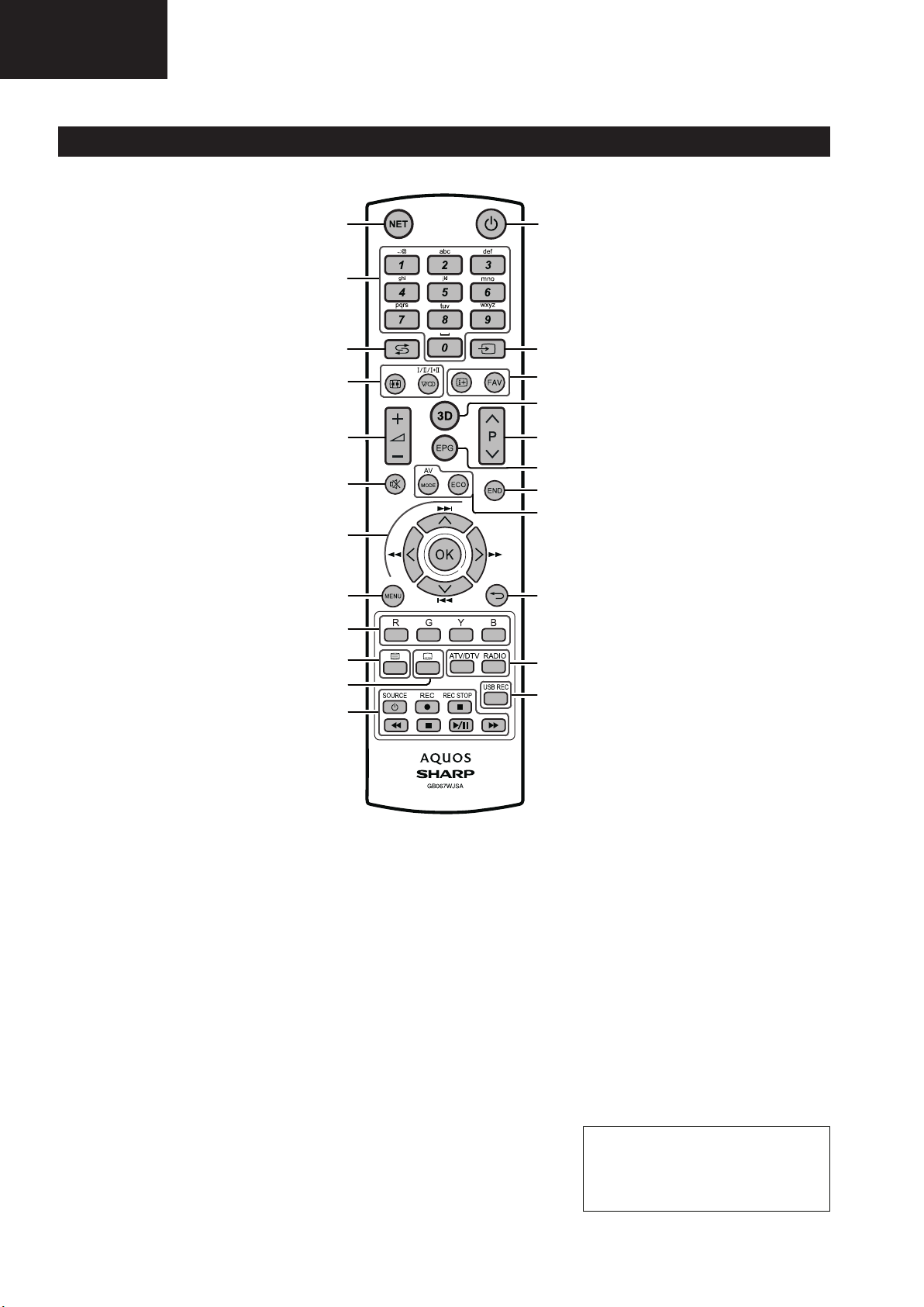
Remote control unit
OPERATION MANUAL
1 NET (Page 37)
Access “AQUOS NET+” mode.
2 Alphanumeric buttons 0_9
Set the channel. Enter desired
numbers. Set the page in teletext
mode.
• When the five Nordic countries
(Sweden, Norway, Finland,
Denmark or Iceland) are selected
in the country setting from initial
auto installation (Page 9), DTV
services are four digits. When
another country is selected, DTV
services are three digits.
3 A (Flashback)
Return to the previously selected
channel or external input.
4 7 (Sound mode) (Page17)
Select a sound multiplex mode.
f Picture format (Page 31)
Change between different picture
formats.
5 i+/- (Volume)
Increase/decrease TV volume.
6 e (Mute)
TV sound on/off.
7 a/b/c/d (Cursor)
Select a desired item.
;
Execute a command.
ATV/DTV/SAT: Display “CH list” when
no other “MENU” screen is running.
T/S/V/U
Not used.
8 @
Main menu screen on.
Come back to last option selected
within MENU screen.
9 R/G/Y/B Colour buttons
The coloured buttons are
correspondingly used to select the
coloured items on the screen (e.g.,
EPG, MHEG-5, teletext).
10 m Teletext (Page 20)
ATV: Display analogue teletext.
DTV/SAT: Select MHEG-5 or teletext
for DTV/SAT.
11 [ Subtitle (Pages 17 and 20)
Switch subtitle languages on/off.
1
23
2
3
4
22
21
20
5
19
18
6
17
16
7
8
15
9
10
11
14
13
12
12 S/I/J/E/H (Pages 49 and
53)
Video/Music/USB REC files
reproduction buttons.
a SOURCE (Page 44)
Operating HDMI-CEC device.
13 USB REC (
Record a programme you are
watching.
Page 49)
14 ATV/DTV
Access TV mode.
RADIO
DTV/SAT: Switch between radio and
data mode.
• When only data broadcasting
(no radio broadcasting) is
transmitted by DVB, the radio
broadcasting will be skipped.
15 6 Back
ATV/DTV/SAT: Return to the previous
“Menu” screen.
NET: Return to the previous page
(This may not function for some
services).
16 Picture adjustment (Page 21)
Select picture settings.
ECO (Page 21)
Activate/deactivate low consumption
mode (ECO).
17 >
ATV/DTV/SAT: Exit the “Menu”
screen.
18 EPG (Page 18)
DTV/SAT: Display the EPG screen.
19 :r/s
ATV/DTV/SAT: Select the TV
channel.
NET: Scrolls pages up/down.
20 3D (Page 54)
Select between 3D and 2D image
viewing.
21 p Channel information (Page 15)
Display the station information
(channel number, signal, etc.) on the
screen.
Within MENU screen shows a hint
about item selected.
FAV
Define active station as favourite.
22 b (AV selection) (Page 17)
Select an input source.
23 a (Standby/On) (Page 17)
Important information:
Satellite services are only
available for the LE652/654
model series.
6
Operation Manual (Continued)
Introduction
4
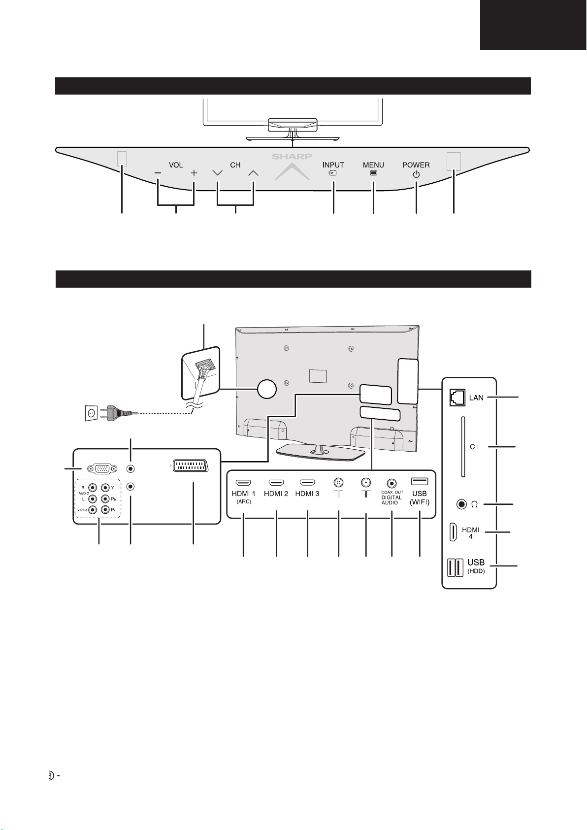
TV (Front view)
*TV indicator status (Page 17)
TV (Side and rear view)
Remote
Control
Sensor
Volume
buttons
Illumination led*
Programme (channel)
buttons
Input
source
button
Menu
button
Power
button
LC-39/50LE650
LC-39/50LE651
LC-39/50LE652
3D infrared
emitter
18
17
1
16
PC IN
2
3
4
HDMI/PC
ANALOG
AUDIO
INPUT
SERVICE
SCART (AV / RGB / S-VIDEO)
5
ANT
SAT
6
7 8
10
9
12
11
15
14
13
1 Analog AUDIO input for DVI and PC
(Jack 3.5mm connector)
2 PC Input
3 COMPONENTS / AV terminals
4 SERVICE connector (jack 3.5 mm)
5 SCART (AV/RGB, Y/C Input) terminal
6 HDMI 1 (HDMI/DVI/ARC)
7 HDMI 2 (HDMI/DVI)
8 HDMI 3 (HDMI/DVI)
9 Antenna input terminal
10 SAT (Satellite antenna input) (Only
L*652 series)
11 Digital Audio Output terminal (SPDIF)
12 USB terminal (Wi-Fi use only)
13 USB terminal (USB REC / MEDIA
PLAYER / SOFTWARE / HDD READY
/ 3D GLASSES BATTERY)
14 HDMI 4 (HDMI/DVI)
15 HEADPHONES jack
16 COMMON INTERFACE slot
17 LAN terminal
18 AC INPUT terminal
WARNING
• Excessive sound pressure from earphones and headphones can cause hearing loss.
• Do not set the volume at a high level. Hearing experts advise against extended listening at high volume levels.
7
LC-39/50LE650
Preparation
LC-39/50LE651
LC-39/50LE652
Operation Manual (Continued)
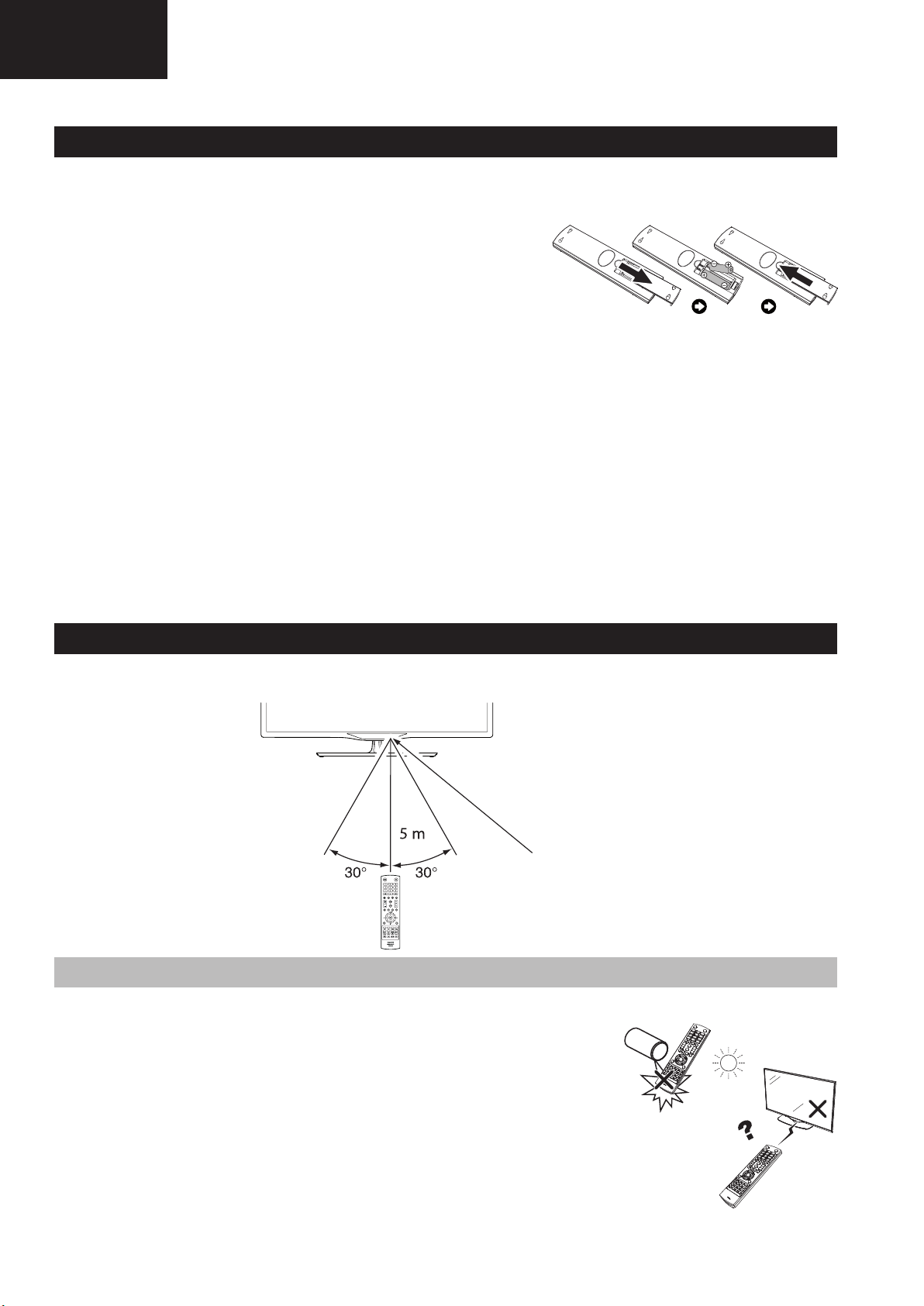
Inserting the batteries
Before using the TV for the first time, insert the two supplied “AAA” size batteries. When the batteries become
depleted and the remote control unit fails to operate, replace the batteries with new “AAA” size batteries.
1 Open battery cover.
2 Insert two supplied “AAA” size batteries.
• Place batteries with their terminals corresponding to
the (+) and (-) indicators in the battery compartment.
3 Close the battery cover.
CAUTION
Improper use of batteries can result in chemical leakage or explosion. Be sure to follow the instructions below.
• Do not mix batteries of different types. Different types of batteries have different characteristics.
• Do not mix old and new batteries. Mixing old and new batteries can shorten the life of new batteries or cause
chemical leakage in old batteries.
• Remove batteries as soon as they have worn out. Chemicals that leak from batteries can cause a rash. If you fi nd
any chemical leakage, wipe thoroughly with a cloth.
• The batteries supplied with this product may have a shorter life expectancy due to storage conditions.
• If you will not be using the remote control unit for an extended period of time, remove the batteries from it.
• When replacing the batteries, use zinc-carbon batteries instead of alkaline ones.
Note on disposing batteries:
The batteries provided contain no harmful materials such as cadmium, lead or mercury.
Regulations concerning used batteries stipulate that batteries may no longer be thrown out with the household
rubbish. Deposit any used batteries free of charge into the designated collection containers set up at commercial
businesses.
Using the remote control unit
Use the remote control unit by pointing it towards the remote control sensor. Objects between the remote control
unit and sensor may prevent proper operation.
Remote control sensor
Cautions regarding the remote control unit
• Do not expose the remote control unit to shock. In addition, do not expose the remote control unit to liquids,
and do not place in an area with high humidity.
• Do not install or place the remote control unit under direct sunlight. The heat
may cause deformation of the unit.
• The remote control unit may not work properly if the remote control sensor of
the TV is under direct sunlight or strong lighting. In such cases, change the
angle of the lighting or the TV, or operate the remote control unit closer to the
remote control sensor.
8

Operation Manual (Continued)
Quick guide
Initial installation overview
LC-39/50LE650
LC-39/50LE651
LC-39/50LE652
Follow the steps below one by one when using the TV for the first time. Some steps may not be necessary
depending on your TV installation and connection.
1 2 3
Preparation
Connect an antenna cable to
the antenna terminal (Page 8).
If necessary, insert a CA
card into the CI slot to watch
scrambled broadcasts
(Page 8.)
Power on and
run the auto
installation
Turn on the power using a on
the TV (Page 17).
Run the initial auto installation
(Page 9).
Language, Energy
Efficiency, country, antenna
type settings, etc.
Watch TV
Congratulations!
Now you can watch TV.
If necessary, adjust the
antenna to attain maximum
signal reception (Page 14).
Connect
external devices
Connect external
devices such as a
DVD player/recorder
as instructed (Pages
41, 42 and 43).
Plug in the AC cord (Page 8).
Product shape varies in some countries.
Go to Next.
Start searching
channels
9
Connect external
audio devices such as
speakers/amplifier as
instructed (Pages 41,
42 and 43).
LC-39/50LE650
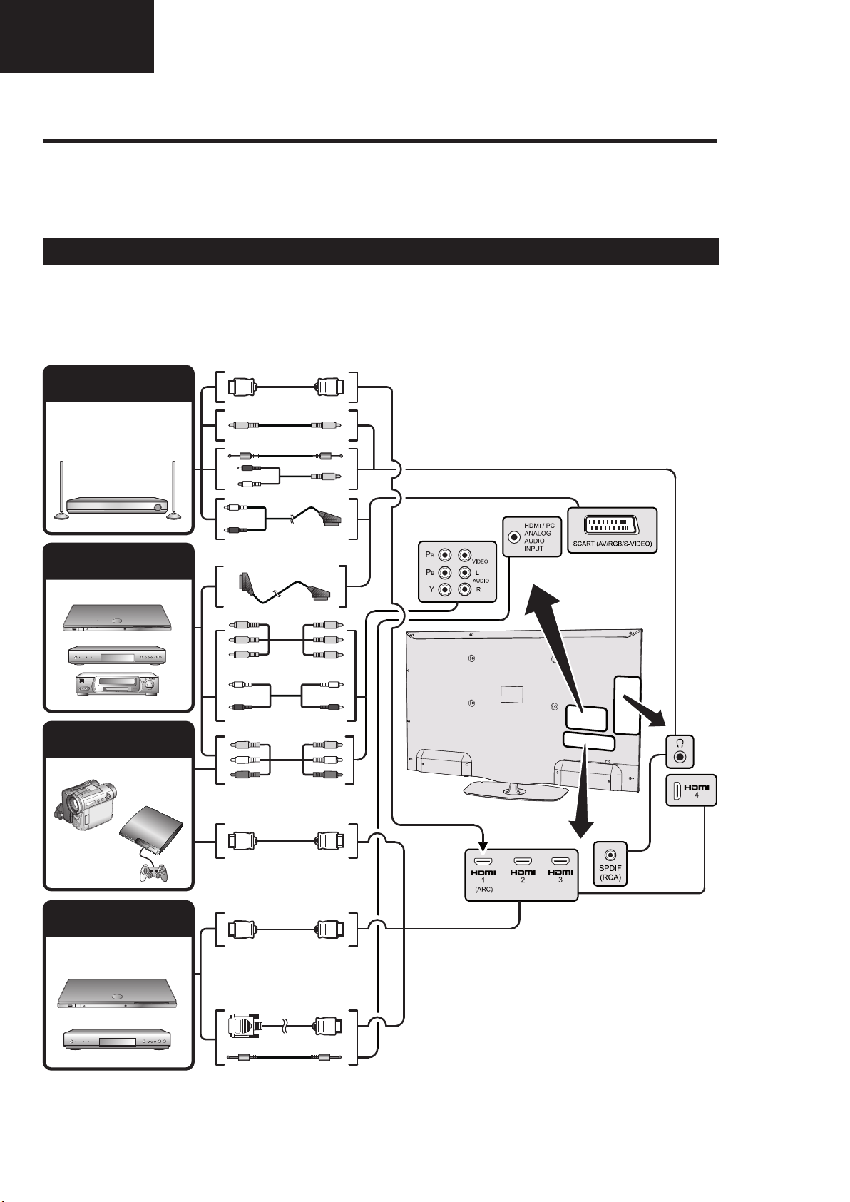
Connecting external devices
LC-39/50LE651
LC-39/50LE652
Operation Manual (Continued)
E Before connecting ...
• Be sure to turn off the TV and any devices before making any connections.
• Firmly connect a cable to a terminal or terminals.
• Carefully read the operation manual of each external device for possible connection types. This also helps you get
the best possible audiovisual quality to maximise the potential of the TV and the connected device.
Introduction to connections
The TV is equipped with the terminals as shown below. Find the cable corresponding the TV’s terminal and connect
the device.
NOTE
• The cables illustrated in pages 41, 42 and 43 are commercially available items.
Audio device
(Page 43)
Video recording device
(Pages 42 and 43)
Game console or
camcorder (Page 42)
HDMI-ARC
Audio cable
Audio cable
SCART cable
Components cable
Audio cable
AV cable
HDMI device
(Page 42)
HDMI-certified cable
HDMI-certified cable
DVI/HDMI Cable
ø 3.5 mm stereo mini jack cable
10
Operation Manual (Continued)
Enjoying 3D image viewing
Display format for 3D and 2D images
Image for input signals Selectable mode Description
3D mode
(using the 3D
glasses)
2D→3D
• Converts normal 2D images into 3D images.
Side by Side
• Creates 3D images from 3D images displayed side
by side. The image is split into a left and right image,
and then the images are stretched and displayed
sequentially to create a 3D image.
Top and Bottom
• Creates 3D images from 3D images displayed
on the top and bottom. The image is split into a
top and bottom image, and then the images are
stretched and displayed sequentially to create a 3D
image.
2D mode
(without using
the 3D glasses)
Side by Side s 2D
• Creates 2D images from 3D images displayed
side by side. Only the left image is stretched and
displayed. The image does not appear in 3D.
Top and Bottom s 2D
• Creates 2D images from 3D images displayed on
the top and bottom. Only the top image is stretched
and displayed. The image does not appear in 3D.
Troubleshooting - 3D Images
NOTE
• These 3D glasses are only for use with SHARP LCD TVs supporting 3D.
Appendix
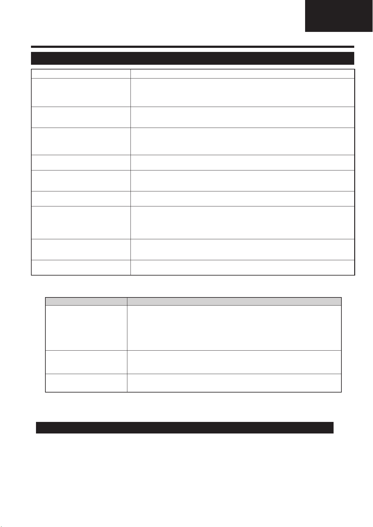
Troubleshooting
Problem Possible Solution
• No power.
• Check if you pressed
a
on the remote control unit.
If the indicator on the TV lights up red, press
a
.
• Is the AC cord disconnected?
• Check if you pressed a on the TV.
• The TV cannot be operated. • External influences such as lightning, static electricity, etc., may cause improper operation. In this
case, operate the TV after first turning off the power, or unplugging the AC cord and re-plugging
it in after one or two minutes.
• Remote control unit does not operate.
• Are batteries inserted with polarity (e, f) aligned?
• Are batteries worn out? (Replace with new batteries.)
• Are you using it under strong or fluorescent lighting?
• Is a fluorescent light illuminating the remote control sensor?
• Picture is cut off. • Is the image position correct?
• Are screen mode adjustments (Picture format) such as picture size made correctly? (Page 31.)
• Strange colour, light colour, or dark
colour, or colour misalignment.
• Adjust the picture tone.
• Is the room too bright? The picture may look dark in a room that is too bright.
• Check the “Picture” settings (Page 21).
• Power is suddenly turned off. • The TV’s internal temperature has increased.
Clean or remove any objects blocking the vent.
• No picture. • Are connections to external equipment correct? (Pages 41, 42 and 43)
• Is the input signal type selected correctly after connection? (Page 14)
• Is the correct input source selected? (Page 31)
• Is the picture adjustment correct? (Pages 21)
• Is the antenna connected properly? (Pages 7 and 14)
• No sound. • Is the volume too low?
• Make sure that headphones are not connected.
• Check if you pressed e on the remote control unit.
• The TV sometimes makes a cracking
sound.
• This is not a malfunction. This happens when the cabinet slightly expands and contracts
according to changes in temperature. This does not affect the TV’s performance.
Appendix
Troubleshooting
Problem Possible Solution
• No power.
• The TV cannot be operated. • External influences such as lightning, static electricity, etc., may cause improper operation. In this
• Remote control unit does not operate.
• Picture is cut off. • Is the image position correct?
• Strange colour, light colour, or dark
colour, or colour misalignment.
• Power is suddenly turned off. • The TV’s internal temperature has increased.
• No picture. • Are connections to external equipment correct? (Pages 41, 42 and 43)
• No sound. • Is the volume too low?
• The TV sometimes makes a cracking
sound.
Problem Possible solution
• 3D images are not displayed. • Is 3D mode set to “Automatic”? Press 3D to switch to 3D mode "Automatic".
• The 3D glasses turn off
automatically.
• Switching the 3D glasses button to
2D or 3D does not cause the LED
to light up green.
Information on the software license for this product
Software composition
• Check if you pressed
If the indicator on the TV lights up red, press
• Is the AC cord disconnected?
• Check if you pressed a on the TV.
case, operate the TV after first turning off the power, or unplugging the AC cord and re-plugging
it in after one or two minutes.
• Are batteries inserted with polarity (e, f) aligned?
• Are batteries worn out? (Replace with new batteries.)
• Are you using it under strong or fluorescent lighting?
• Is a fluorescent light illuminating the remote control sensor?
• Are screen mode adjustments (Picture format) such as picture size made correctly? (Page 31.)
• Adjust the picture tone.
• Is the room too bright? The picture may look dark in a room that is too bright.
• Check the “Picture” settings (Page 21).
Clean or remove any objects blocking the vent.
• Is the input signal type selected correctly after connection? (Page 14)
• Is the correct input source selected? (Page 31)
• Is the picture adjustment correct? (Pages 21)
• Is the antenna connected properly? (Pages 7 and 14)
• Make sure that headphones are not connected.
• Check if you pressed e on the remote control unit.
• This is not a malfunction. This happens when the cabinet slightly expands and contracts
according to changes in temperature. This does not affect the TV’s performance.
• If 3D mode is set to “Automatic” but no 3D images are displayed, check the display format of the
content being viewed. Some 3D image signals may not be recognised as 3D images automatically.
Press 3D to select the appropriate display format for the 3D image.
• Are the 3D glasses set to 3D mode?
• Is there an obstacle between the 3D glasses and the TV, or is something covering the infrared
receiver on the 3D glasses? The 3D glasses operate by receiving a signal from the TV. Do not place
anything between the 3D infrared emitter on the TV and the infrared receiver on the 3D glasses.
• Is there an obstacle between the 3D glasses and the TV, or is something covering the infrared
receiver on the 3D glasses? The 3D glasses turn off automatically after three minutes if no signal
is received from the TV. Do not place anything between the 3D infrared emitter on the TV and the
infrared receiver on the 3D glasses.
• Is the battery in the 3D glasses exhausted? If the LED light does not light after pressing the power
button for more than one second, the battery is exhausted. Recharge the battery via mini USB
connector.
The software included in this product is comprised of various software components whose individual copyrights are held by
SHARP or by third parties.
Software developed by SHARP and/or third part
The copyrights for the software components and various relevant documents included with this product that were developed or
written by SHARP are owned by SHARP and are protected by the Copyright Act, international treaties, and other relevant laws.
This product also makes use of freely distributed software and software components whose copyrights are held by third parties.
a
on the remote control unit.
a
.
LC-39/50LE650
LC-39/50LE651
LC-39/50LE652
11
LC-39/50LE650
LC-39/50LE651
LC-39/50LE652
Operation Manual (Continued)
Multimedia/Network Setup
Network Setup
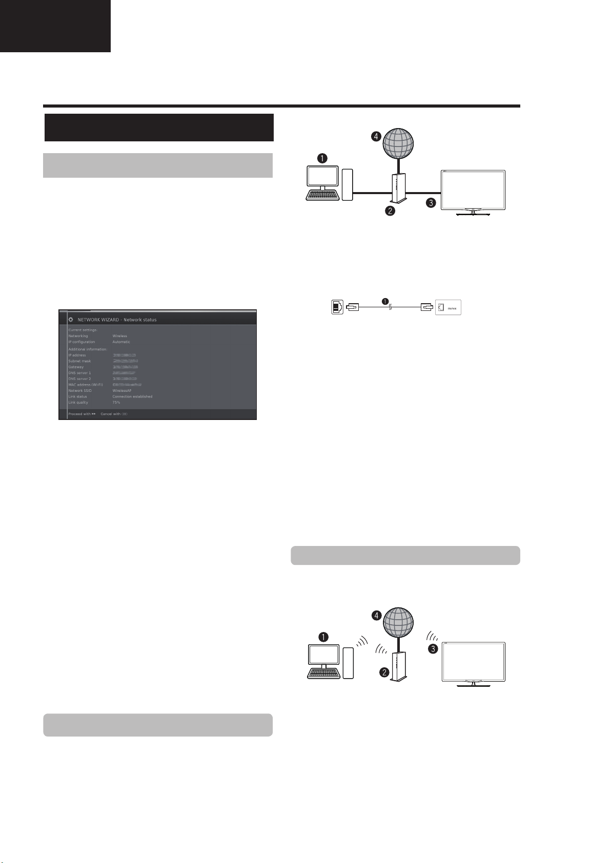
Connecting to the network
To enjoy internet services, you need to connect the TV
to a router with a high speed connection to the internet.
You can also connect the TV to your Home network
server through a router or access point.
The TV connection to the router can either be wired or
wireless.
To access the TV internet confi guration go to
Setup→Multimedia/Network→Network settings→
Networking. The next screen is shown:
Press J to continue the installation.
Choose between Wired or Wireless connection.
NOTE
• If you choose a wired connection to the router, you need
an ETHERNET cable (not included, commercially available).
• If you do not have a broadband internet connection, consult
the store where you purchased your TV or ask your internet
service provider or telephone company.
• Wired and wireless connection cannot be used at the same
time. Use only one of the connection types.
• A wireless LAN connection and performance cannot be
guaranteed for all residential environments. In the following
cases, the wireless LAN signal may be poor or drop, or the
connection speed may become slower.
- When used in buildings made with concrete, reinforced
steel, or metal.
- When placed near objects that obstruct the signal.
- When used with other wireless devices that emit the same
frequency.
- When used in the vicinity of microwave ovens and other
devices that emit a magnetic fi eld, electrostatic charge, or
electromagnetic interference.
• A stable connection speed is required to play back streaming
content. Use a wired LAN connection if the wireless LAN
speed is unstable.
Wired installation
Use an ETHERNET cable to connect the LAN terminal
on the TV to your broadcast router as shown below.
This is recommended when enjoying services which
require stable connection speeds, such as streaming
media.
● Wired connection overview
PC (Home Media Server)
Router (commercially available)
ETHERNET cable (commercially available)
Network (Internet)
● How to connect
lanimret NALretuoR
LAN
LAN
ETHERNET cable
1 Switch on the router (commercially available). Refer to
the router’s operation manual for switching on.
2 Connect the LAN terminal on the TV to the router
(commercially available) with an ETHERNET cable
(commercially available).
3 Go to Setup→Multimedia/Network→Network
settings→Networking.
4 Press OK and ▲/▼ to select “wired”, and then
press OK.
5 Select type of IP configuration:
Automatic: Automatic configuration of the IP
address via DHCP server or via multiple protocols
according to UPnP specification.
Manual: Enter your fixed static IP addresses
manually. (Ask your internet service provider).
6 Press OK.
Wireless installation
Use the SHARP (AN-WUD630) USB adapter with the
TV.
● Wireless connection overview
PC (Home Media Server)
Wireless LAN router/access point
Wireless
Network (Internet)
NOTE
• When using the SHARP wireless LAN adapter, try to provide
as much free space around the device for best performance.
• Make sure the firewalls in your network allow access to the
TV wireless connection.
AN-WUD630
LAN USB adapter
(Sold separately)
12
Operation Manual (Continued)
Multimedia/Network Setup
LC-39/50LE650
LC-39/50LE651
LC-39/50LE652
• Operations cannot be guaranteed when used with access
points that do not have Wi-Fi® certification.
• A wireless LAN access point is required to connect the TV to
the Internet using a wireless LAN. See the operation manual
of your access point for setup.
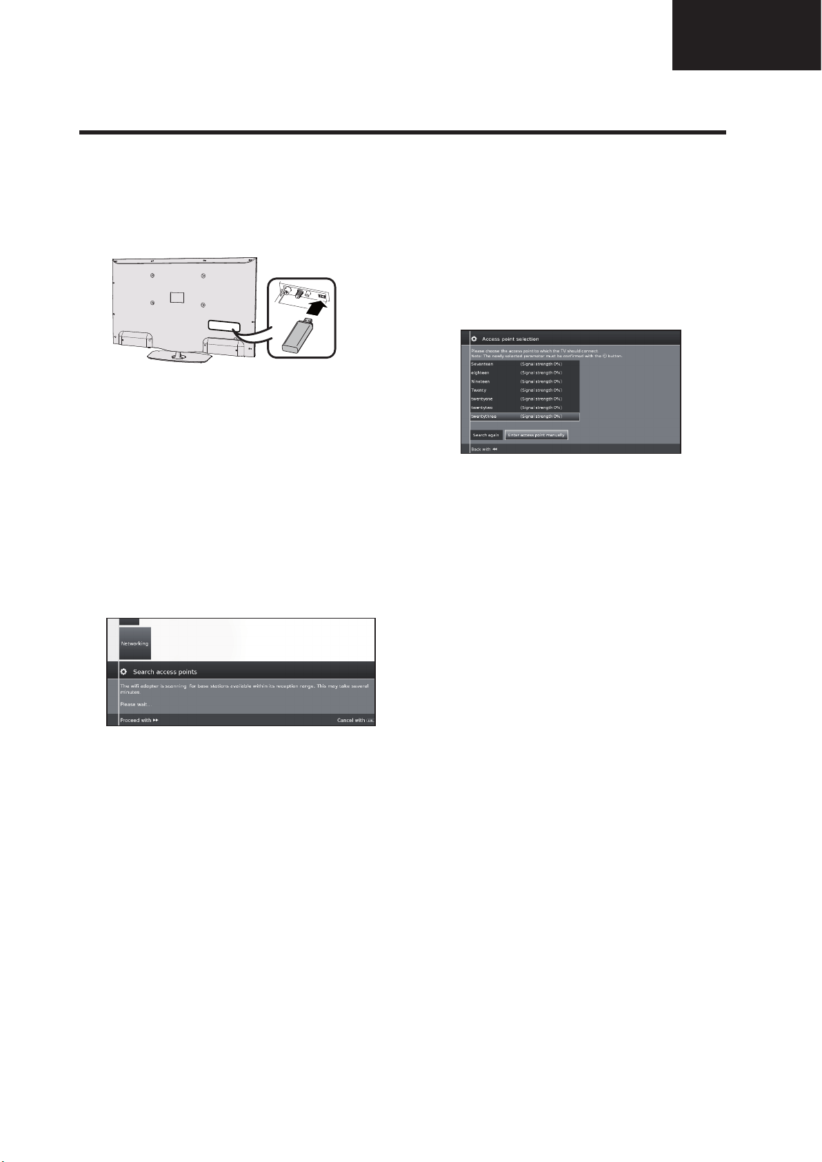
● How to connect
1 Switch on your router/access point before starting
the network installation.
2 Connect the
USB Wi-Fi port on the TV.
• Do not use a wireless LAN adapter other than the ANWUD630 Sharp wireless LAN adapter, as operations
cannot be guaranteed.
• If your wireless network is secured, have the
encryption key ready to enter on screen.
3 Go to Setup→Multimedia/Network→Network
settings→Networking.
4 Press OK and ▲/▼ to select “wireless”, and then
press OK.
The "Wireless" connection will be automatically selected
if the TV detects only the wireless USB adapter.
The TV starts to search for wireless routers/access points.
5 Select required router/access point and press OK.
As soon as ◄◄ is displayed , you can go back one
installation step by pressing this button.
6 If your network has an access code, it is necessary
to enter the code that allows access to the
network. A screen keyboard will appear to enter
the password.
Press OK.
7 Select IP address assignment method. You can
choose between: Automatic (DHCP) or Manual
(Input Static IP Address).
Automatic (DHCP): IP address is automatically
issued by a DHCP server on your home network.
• A DHCP server has to be set up on a device on
the network (WLAN router/access point).
Input Static IP Address: IP address is entered
manually. Use the RC alphanumeric buttons, to
input digits of IP address.
Press
J to continue.
Afterwards you will see a summary of the settings.
8 Press
J to confirm settings.
AN-WUD630
USB adapter to the
NOTES
• To connect your TV to the internet, you must have a
broadband internet connection.
• If you do not have a broadband internet connection, consult
the store where you purchased your TV or ask your internet
service provider or telephone company.
• There is no need to enter the security key for subsequent
connections to the wireless network.
If your access point is set to a stealth mode (Hidden
SSID, that prevents detection by other devices), you
need to use manual method to enter the SSID name for
desired access point.
1 Select Enter access point manually and press
OK. Introduce the SSID name using the on-screen
keyboard.
2 Select Adopt and press OK to fi x the name.
3 Select Encryption method and press OK.
Only if your access point is secured a WEP key or a
WAP password will be required.
4 Repeat the process from point 7 of previous
explanation.
To change wireless LAN connection settings, go to
Setup → Multimedia/Network → Network settings
→ Networking.
NOTES
• Any low bandwidth adapter (router, hub, wireless access
point,…) will show poor network connection and then, poor
streaming quality. It is recommended 56 Mbps or higher
bandwidth for full feature.
• Working in close proximity to other Wireless/Bluetooth
networks, may cause some trouble using a Wi-Fi adapter on
the internet connected TV. Because the wireless link cannot
be guaranteed, please try to change the Wi-Fi channel on
the Access Point (AP) to avoid interference. Please refer to
Access Point User Manual.
• Home Media (DLNA) requires external streaming media
software installed on a PC, inside the HOME Network, that
is not included with AQUOS NET+.
• Home Media (DLNA) server software as Windows Media
Player 11 (Windows Vista included) or Windows Media
Player 12 (Windows 7 included), TVersity (www.tversity.
com), Nero Media Home (www.nero.com), or Twonky Media
Manager (www.twonky.com) are preferred but others can
also be used. Visit the DLNA website (www.dlna.org) to see
the certifi ed media server list. Follow the server software’s
user manual for setup, share and stream media contents.
• Home Media (DLNA) (Video, Music and Photo) data is
organised in folders depending on the Server hierarchy;
options such as Artist, Genre, Composer, Ratings, Playlist
or Watch Folders may be present for sorting content, but
can be different depending on the selected Media Server.
• The “Play To” function of some PC Media Players may result
in very compressed video quality. For best video quality,
please use the USB Media Player function of the TV.
13
LC-39/50LE650
LC-39/50LE651
LC-39/50LE652
Operation Manual (Continued)
TV menu options
AQUOS NET+ function
AQUOS NET+ option allows you to access to AQUOS
NET+ feature and Internet browser.
For this option it is necessary that the TV set is
connected to Internet (See page 47).
1 Press @ button, select AQUOS NET+ and
press OK. The next screen appears:
2 Press > to exit.
What is AQUOS NET+?
Operations in AQUOS NET
+
Basic Operation
The illustrations on this page are for explanation
purposes. They are subject to change without notice.
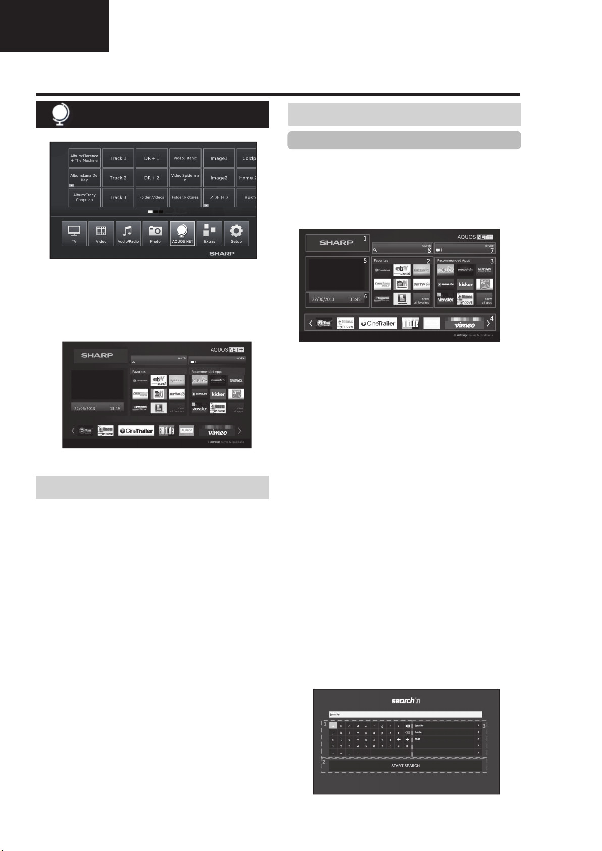
E Display the AQUOS NET+ screen
Press NET on remote control or select AQUOS NET+
on main menu to open AQUOS NET+ home page.
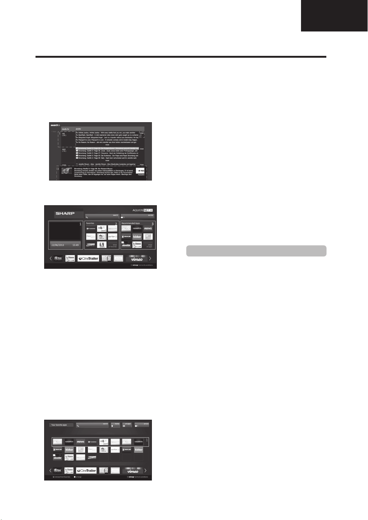
AQUOS NET+ screen is organised into 8 areas:
AQUOS NET+ title banner
User-defined Favorites
Recommended Apps
Interactive windows for direct brand communications
or maintenance functions
Media window
Widget Area-real-time functions like date and time
or similar
Sharp Service Center
Interactive Search window
AQUOS NET+ is the feature that allows our Internet
connected TV sets to easily reproduce digital media
content coming from the Network. It provides access to
Internet services (Internet browser, YouTube, Facebook
and much more)
AQUOS NET+ provides a variety of services for each
country.
NOTES
• As AQUOS NET
over time to better serve its purpose.
• Some AQUOS NET
discontinued after some time.
+
is an online system, it can be modifi ed
+
services may be added, changed or
• Even in opern web-mode, users cannot download and save
fi les or install plugins.
DISCLAIMERS
• SHARP Corporation bears no responsibility regarding
the content and quality of the content provided by the
content service provider.
E Select a service
On AQUOS NET+ screen use▲/▼/◄/► to select the
desired service, and then press OK to start it.
• Press 6 to return to the previous page.
You can also use "Search" utility to fi nd specifi c services,
related to a search term.
•
Select "Search"
search page or start typing to directly search to
specific terms.
• T
o search for a specific keyword, the word is
entered using the virtual keyboard (1). The search
is executed by clicking Start Search (2). The history
of tthe last search terms can be found on the right
side (3).
and press OK to access the
14
Operation Manual (Continued)
TV menu options
LC-39/50LE650
LC-39/50LE651
LC-39/50LE652
After searching for a specific term, the results are
categorized by their type (1), including the number
of search results. Categories can be hidden and
expanded on request by selecting the close button
(2) in the results overview.
Resting the cursor on a search result will bring up a
preview overlay (3) with information of the selected
content.
E User sections
The Home Screen is devided in 3 functional areas:
1 Interactive Media Area
This segment is used for the audio-visual
presentation of various types of content.
2 Favorite Apps Area
This area presents the top 8 apps of the userdefi ned favorite applications, including a link to
all user-defi ned favorite applications.
3 Recommended Apps Area
This area presents a selection of recommended
apps and also includes a link to the “all apps”
screen as described below.
In Area 2 and 3, please use ◄/►/▲/▼ to select a
service you want to access and press OK, direction
arrows appear around the service logo.
E Favorite Apps Screen
This screen gives an overview of all user-defi ned
favorites. Favorites can be selected in the all-apps
screen, as described below. The Top row of apps
is presented on the home-screen. The fi rst row
(1) is automatically presented in the favorite apps
section on the home screen.
Apps can be re-arranged by the user:
1
Move the cursor to the application that shall be moved.
2 Use Yellow color key to enter arrange-mode.
3 Move selected service to the desired position and
press the yellow color key again to confi rm the new
position.
To dismiss an application from the favorite Apps, place
the cursor on the respective app and press the RED
color-key on the remote control.
E Exit AQUOS NET+ screen
Press MENU button and select TV to return to tv mode.
You can also press AT V, DTV, SAT or RADIO button
to exit.
NOTES
• When connecting the TV to the Internet, a message which
requests a software update may be displayed in some
cases.
• Some services can request to the user to Login or create a
personal account. In this case, please follow the indication
on the screen.
• PREMIUM Video-on-Demand (VOD) services are available
in some countries.
• The illustrations on this page are for explanation purposes.
They are subject to change without notice.
• AQUOS NET+ screen language is adapted to the TV set
language previously selected.
• While AQUOS NET+ is active some TV menus or options
could be disabled.
Advance Operation
AQUOS NET+ uses alphanumerical characters within
some services, which can be introduced using the
remote numerical keys, in a similar way that people
use a mobile phone keypad. In order to make this
task easier, the LE650 is ready to use an external USB
keyboard (USB wired, USB-to-Wireless or USB-toBluetooth ready) to work only inside AQUOS NET+.
When an external keyboard is installed on TV set and
the user select AQUOS NET+, then the keyboard
mapping is:
(ENTER)/INTRO = OK (R/C). Used to enter inside
1
any service or to fix data once inside.
2 ◄/►/▲/▼ (U/O/I/K, or u/o/i/k for not extended
keyboard). Used to move between services or scroll
pages on Left/Right direction.
3 ESCape =6 (Return R/C). Return to previous page
on services.
4 (Backspace). Erase last character entered.
5 A..Z,a..z,0..9, and some US symbols (period or dot,
commercial at @, underscore, hyphen, exclamation,
question, colon, opening parenthesis, closing
parenthesis, number, slash, backslash, space).
Used for Login, Passwords, Date, and so.
NOTES
• The TV does not support hot plug connection of USB
devices like a keyboard. If you wish to connect any other
device, please do it when the TV is Power Off or in Standby.
• Inside AQUOS NET+ services, please use standard US
characters only (Not extended characters or Special
Country Language dependent), in order to avoid problems
with the applications.
• Using external USB keyboard is not possible to exit from
AQUOS NET+. If necessary, use the END remote key.
• Some types of keyboard could show incompatibilities or
try to use functions not supported by the TV.
15
LC-39/50LE650
LC-39/50LE651
LC-39/50LE652
Operation Manual (Continued)
Quick guide
Initial auto installation
When the TV is powered on for the first time after
purchase, the initial auto installation wizard appears.
Follow the menus and make the necessary settings one
after another.
Confirm the following before turning
on the power
E Is the antenna cable connected?
E Is the AC cord plugged in?
1 Press a on the TV.
• The initial auto installation wizard appears.
• The auto installation can also be called in the TV menu,
see Repeat initial installation on page 40.
• The routine of the first installation wizard depends on
the selected settings.
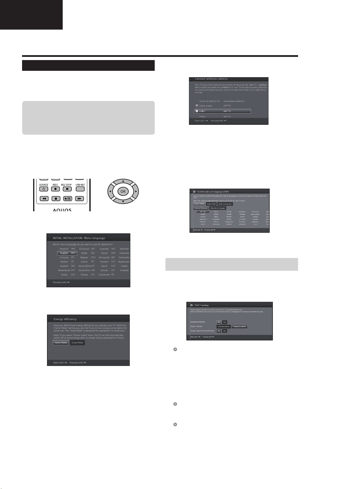
2 Setting the menu language.
Press
a/b/c/d to select the desired language.
5 Select broadcast settings.
Press ▲/▼ to move between different tune type.
Press OK to select the desired antenna.
Cable analogue: analogue broadcast via cable/
DVB-T: Digital broadcast.
DVB-C: Cable digital broadcast.
DVB-S: Satellite broadcast.
antenna.
(Only 652/654 series
(Only 752/754 series)
Proceed with J button.
6 Select subtitles and audio languages.
Press
a/b/c/d and OK to select the desired
languages and alternative languages for subtitles
and audio for DVB programmes.
)
Proceed with
J button.
3 Setting Energy Efficiency.
Decide how efficiently you want to operate your TV
set.
•Home Mode:
The emphasis for home use is on low energy
consumption.
•Shop Mode:
The picture settings are aligned to operate in the
presentation room. If the ambient brightness diminishes,
the energy consumption is not reduced.
This setting can be changed later in the MENU
Extras→Energy Efficiency.
Proceed with J button.
4 Selecting the TV location.
Press ▲/▼/◄/► to select your country or area.
• This setting screen only appears during the initial auto
installation.
Proceed with J button.
Proceed with
•
To set up audio commentary for the visually impaired, please
see Audio commentary on page 25.
J button.
Setting options for DVB-T reception
If you have not selected DVB-T antenna in the antenna
selection, continue with Setting options for DVB-C
reception on page 10.
7 Selecting tuner settings.
● Scrambled stations
You can specify if coded stations are to be searched
for in the search/update.
Select yes to save all scrambled stations.
•
These stations can only be received in connection with a CI
module and the appropriate CA Card.
•
If a CI module with a CA Card is already inserted for the station
search, all the stations which this module can descramble are
also saved when no is selected.
● Search method
Select Frequency search if you want to run the
station search independently of the channel grid.
●
Accept logical channel number
In various countries, digital stations are transmitted
with a preset channel number per station, known as
"Logical Channel Numbers" (LCN).
If you select yes, these default channel numbers will
be used and the channels will be sorted as per LCN.
16
Operation Manual (Continued)
Quick guide
LC-39/50LE650
LC-39/50LE651
LC-39/50LE652
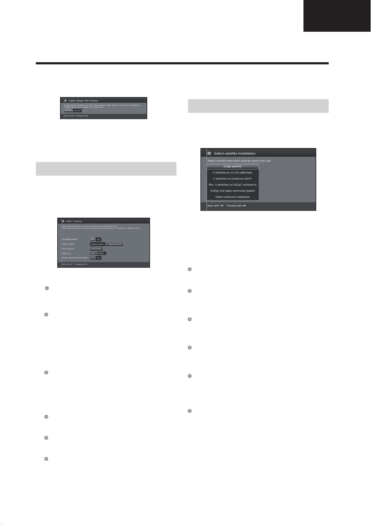
8 Supplying power to the antenna.
If you use a DVB-T antenna that requires a supply voltage
and which is not supplied via a power adapter, then select
yes (5V) for the antenna's power supply.
Press J button.
How to align your DVB-T antenna is described on
page 14.
9 Continue with Settings for all types of reception
(See page 13).
Setting options for DVB-C reception
If you have not selected DVB-C antenna in the
antenna selection, continue with Setting options for
DVB-S reception below.
The normal DVB-C settings are derived from the
selection of the location and do not need to be changed.
Press ▲/▼/◄/► to change each item to the appropriate
settings:
● Network selection
If several networks are available via DVB-C, you
can decide which network you want to receive your
channels from.
● Scrambled stations
You can specify if coded stations are to be searched
for in the search/update.
Select yes to save all scrambled stations.
•
These stations can only be received in connection with a CI
module and the appropriate CA Card.
•
If a CI module with a CA Card is already inserted for the station
search, all the stations which this module can descramble are
also saved when no is selected.
● Search method
If you select Frequency Search, a search is
performed for all receivable stations. With Network
Search, only the stations which the networks
supply are searched, either for all receivable
networks or only for the particular network specified
under Network ID.
● Start Frequency
The DVB stations are only searched for in the
frequency range above the start frequency.
● Network ID
Change this setting to register only the specified
network ID.
● Accept logical channel number
In various countries, digital stations are transmitted
with a preset channel number per station, known as
"Logical Channel Numbers" (LCN).
If you select yes, these default channel numbers will
be used and the channels will be sorted as per LCN.
NOTE
• The value of Frequency and Network ID should
be set to the value specified by the cable provider.
Press
J to continue.
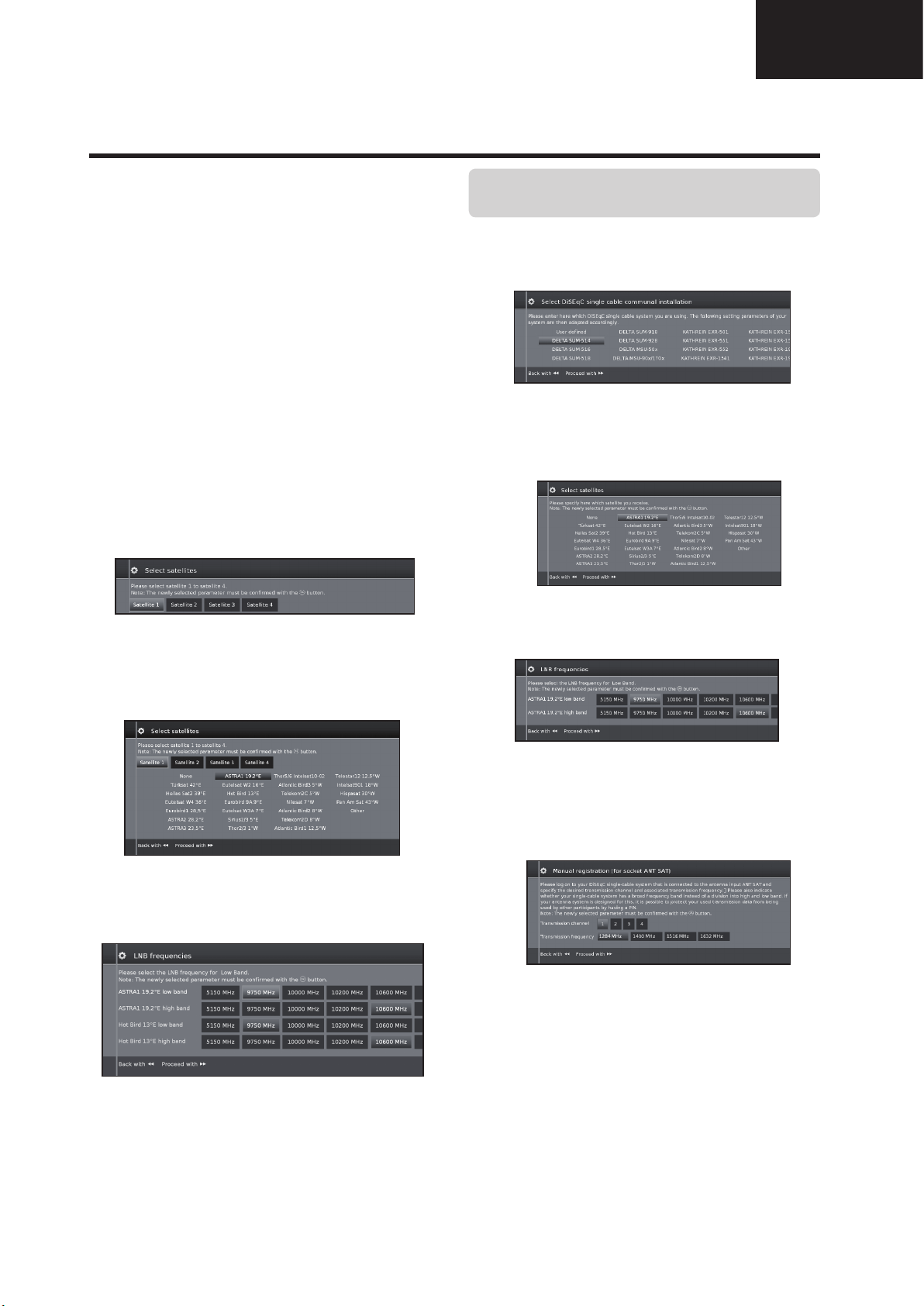
Setting options for DVB-S reception
If you have not selected a DVB-S antenna in the
antenna selection, continue with Settings for all types
of reception on page 13.
Select the satellite system.
Specify how you receive which satellite(s) (single
satellite or type of satellite system). Ask your dealer in
this regard.
The normal DVB-S settings are derived from the
selection of the location and do not need to be changed
in most cases.
●
Single satellite
Reception of a single satellite via a connected LNC
(LNB). See page 11 for settings.
●
2 satellites on 22kHz switchbox
Reception of two different satellites with two LNCs
(LNBs) which are connected to the TV set by a 22
kHz switchbox. See page 11 for settings.
●
2 satellites on Toneburst switch
Reception of two different satellites with two LNCs
(LNBs) which are connected to the TV set by a
toneburst switch. See page 11 for settings.
●
Max. 4 satellites on DiSEqC multiswitch
The TV set controls a DiSEqC multiswitch to which
up to four LNCs (LNBs) for different satellites are
connected. See page 11 for settings.
●
DiSEqC one cable communal system
Select setting if the TV set is connected to a DiSEqC
single cable system (according to EN50494). Several
satellite receivers can be connected to one satellite
cable. See page 12 for settings.
●
Other communal installation
Select this setting if the TV set is connected to a
single-cable system (without DiSEqC). Several
satellite receivers can be connected to one satellite
cable. As opposed to a DiSEqC one cable system
there are restrictions in the range of certain reception
frequencies in common single-cable community
systems. See page 13 for settings.
Press
J to continue
17
LC-39/50LE650
LC-39/50LE651
LC-39/50LE652
Operation Manual (Continued)
Quick guide
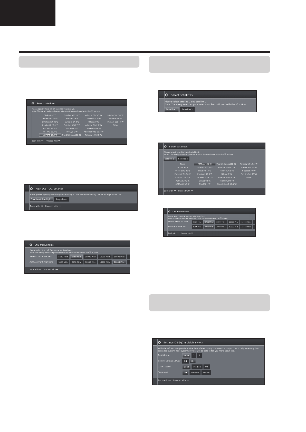
Setting options for Single satellite
Reception of a single satellite via a connected LNC
(LNB).
1 Select satellite.
Press
J to continue.
2 Select Dual Band (low/high) or Single Band.
Here you specify if you use a Dual Band (Universal)
LBN or Single LBN.
Setting options for 2 satellites on 22kHz
switchbox / 2 satellites on Toneburst switch
1 Select Satellite1/Satellite2
2 Select satellite name from list and press OK.
Press
3 Specify here the oscillator frequency for your LNB.
J to continue.
Press
J to continue.
3 Specify here the oscillator frequency for your LNB.
Normally you do not need to change the values
for high and low band, unless the LNB of your
satellite system uses a different oscillator frequency
(important for the frequency display).
If you use the setting Single Band in step Dual/
Single Band, you only have to define the LNB
frequency for the Low Band.
4 Press
See Setting options for all DVB-S reception on
page 13 to continue.
J to continue.
Normally you do not need to change the values
for high and low band, unless the LNB of your
satellite system uses a different oscillator frequency
(important for the frequency display).
4 Press OK to select frequency and press
continue.
See Setting options for all DVB-S reception on
page 13 to continue.
J to
Setting options for Max. 4 satellites on DiSEqC
multiswitch
Select DiSEqC multiswitch and adpat settings for this
selection.
18
Operation Manual (Continued)
Quick guide
LC-39/50LE650
LC-39/50LE651
LC-39/50LE652
● Repeat rate
The refresh rate determines how often a DiSEqC
command is output. A refresh is only necessary with
cascaded system.
● Control voltage
The control voltage controls the switch of the
polarisation level (horizontal/vertical) in non-DiSEqC
capable components (e.g., control of single LNBs
via DiSEqC multiswitch).
● 22kHz signal
The 22kHz signal controls the switching between
high and low band in the Band setting. The Position
setting controls the selection of the satellites in nonDiSEqC capable components.
● Toneburst
The Toneburst controls the selection of the satellites
in non-DiSEqC but Toneburst capable components
with the Position and Option settings.
Press OK to adopt settings and press J to continue.
1 Select Satellite1 to Satellite4.
Setting options for
DiSEqC one cable
communal system
1 Select which DiSEqC single cable system you are
using and press OK.
2 Select satellite name from list and press OK. Press
J to continue.
3 Specify here the oscillator frequency for your LNB
and press OK. Press
J to continue.
2 Select satellite name from list and press OK. Press
J to continue.
3 Specify here the oscillator frequency for your LNB.
Normally you do not need to change the values
for high and low band, unless the LNB of your
satellite system uses a different oscillator frequency
(important for the frequency display).
See Setting options for all DVB-S reception on
page 13 to continue.
Normally you do not need to change the values
for high and low band, unless the LNB of your
satellite system uses a different oscillator frequency
(important for the frequency display).
4 Select and adjust settings for DiSEqC single cable
communal installation.
Select the desired transmission channel and the
corresponding transmission frequency.
PIN protection
If your system is designed for it, it is possible to
protect your used transmission data from use by
other subscribers with a PIN.
Define/change PIN
Here you can determine and change the PIN for
PIN protection. Only possible when yes has been
selected for PIN protection.
Continue with Setting options for all types of
reception on page 13.
19

LC-39/50LE650
LC-39/50LE651
LC-39/50LE652
Operation Manual (Continued)
Quick guide
Setting options for Other communal installation
1 Select satellite.
Press
J to continue.
2 Specify here the oscillator frequency for your LNB.
If your set is connected to a single-cable system
without external voltage supply, you can connect
the antenna supply (13V or 18V / max. 450mA)
with 13V or 18V.
● Scrambled stations
Select yes to save all scrambled stations.
• These stations can only be received in connection
with a CI module and the appropriate CA Card.
• If a CI module with a CA Card is already inserted
for the station search, all the stations which this
module can descramble are also saved when no
is selected.
●
Search method
If you select Frequency Search here, a search is
performed for all receivable stations. With Network
Search, from all receivable networks all the stations are
searched which are supplied by these networks.
●
Symbol rate
The symbol rate is specified by the satellite provider and
normally does not need to be changed.
●
Accept Logical Channel Number
This setting allows you to decide whether you want to
accept the Logical Channel Number (LCN).
Press
J to continue.
Continue with Setting options for all types of
reception below.
Setting options for all types of reception
Continue with Setting options for DVB-S reception
below.
Setting options for DVB-S reception
●
Network selection
If several networks are available via DVB-S, you
can decide which network you want to receive your
channels from.
●
Settings
If several satellites are received, the following settings
must be made for every satellite. The type of settings
available may differ depending on the selected satellite
or network.
●
Age related lock
Allows you to restrict programmes depending on the age
classification.
The information about age classification is provided by
the broadcasting station.
The stations locked can only be watched after entering
the access code (see page 24).
●
Time and date
Enter the correct values with the numeric buttons here.
● Network configuration
Here you can now specify if you wish to configure a
network "Configure now" (see page 47) or you wish
to configure it later "Do not configure or configure
later".
20
Operation Manual (Continued)
Quick guide
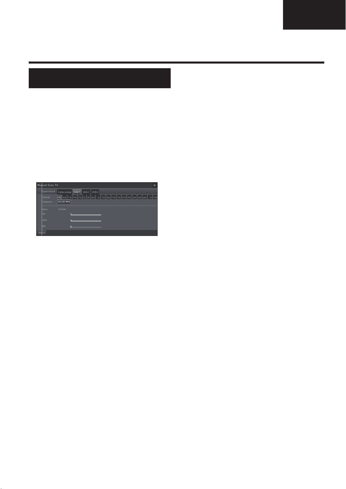
Positioning / aligning DVB-T
antenna
If you install a DVB-T/T2/S/S2 antenna for the first time
or relocate it, you should adjust the alignment of the
antenna to receive a good reception while checking the
antenna setup screen.
In normal TV mode, without other displays, a DVB-T
station is received and selected.
1 Select Setup.
2 Select Stations.
3 Select Manual Scan TV.
LC-39/50LE650
LC-39/50LE651
LC-39/50LE652
Position and align the antenna in such a manner that
maximum values for C/N and Level are obtained.
The value for BER should be as low as possible.
4 Select Search and press OK to start search.
21
LC-39/50LE650
LC-39LE650E/V LC-50LE650E/V
LC-39LE651E/K/V LC-50LE651E/K/V LC-60LE651E/K
LC-39LU651E LC-50LU651E LC-60LU651E
LC-39LE652E/V LC-50LE652E/V LC-60LE652E
LC-39LM652E/V LC-50LM652E LC-60LM652E
LC-39LK652E LC-50LK652E LC-60LK652E
LC-39LX652E LC-50LX652E LC-60LX652E
LC-39LE654E/V LC-50LE654E/V LC-60LE654E
LC-39/50LE651
LC-39/50LE652
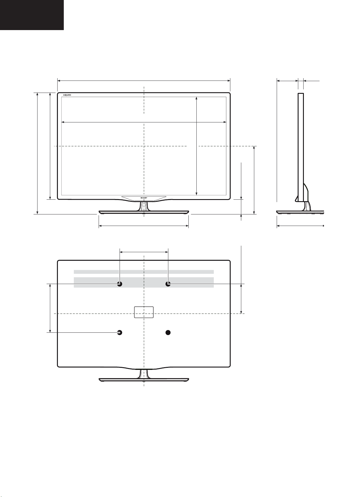
DIMENSIONS
(881) / [1123] / [(1368)]
(859) / [1100] / [(1335)]
(517) / [654] / [(798)]
(590) / [727] / [(871)]
(457) / [485] / [(585)]
(483) / [620] / [(754)]
(73) / [74] / [(73)]
(337) / [406] / [(478)]
(83)
[88]
[(125)]
(242) / [265] / [(308)]
(41)
[41]
[(41)]
(200) / [200] / [(400)]
(200) / [400] / [(400)]
(183) / [206] / [(230)]
39”: ( )
50”: [ ]
60”: [( )]
22
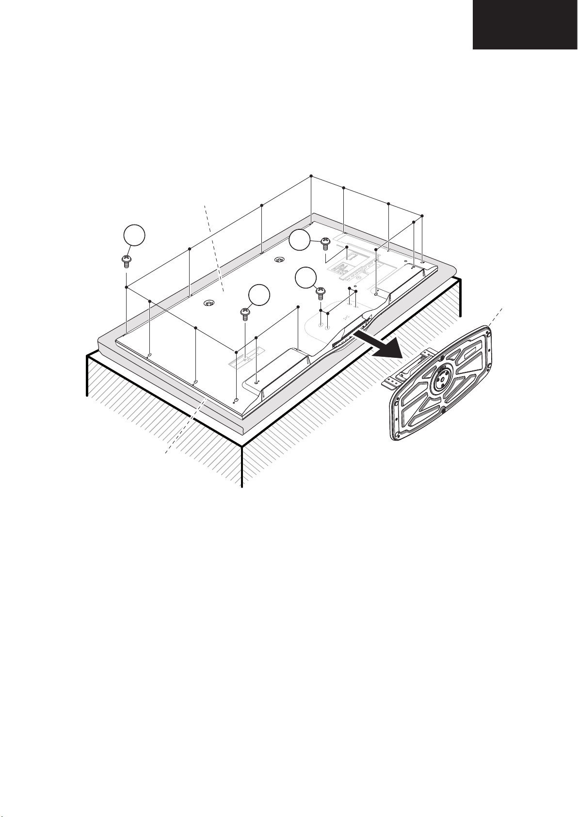
1. Removing of major Parts 39”
LC-39LE650
1 / 5
LC32D44E-BK
Service Manual
CHAPTER 2.
REMOVING OF MAJOR PARTS
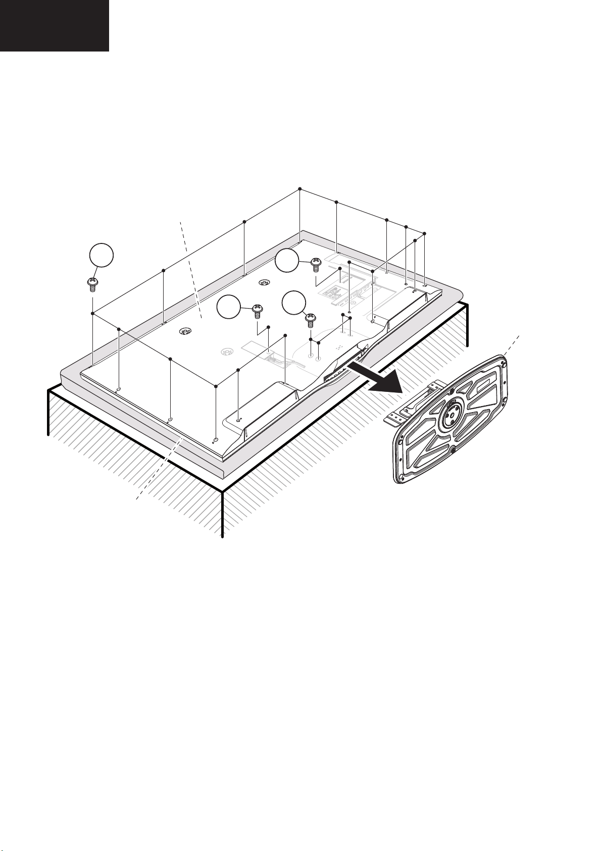
[1] REMOVING OF MAJOR PARTS
1. Remove the 4 lock screws and detach the Stand.
2. Remove the 14 lock screws , 1 lock screw , 1 lock screw and detach the AC cord cover and the Rear Cabinet.
2
1
3
4
2
front
CABINET
rear
CABINET
1
3
4
STAND
1.1. Remove the 4 lock screws and detach the Stand.
1.2. Remove the 14 lock screws , 1 lock screw , 1 lock screw and detach the AC cord cover and Rear Cabinet
REMOVING OF MAJOR PARTS
LC-39/50LE650
LC-39/50LE651
LC-39/50LE652
23
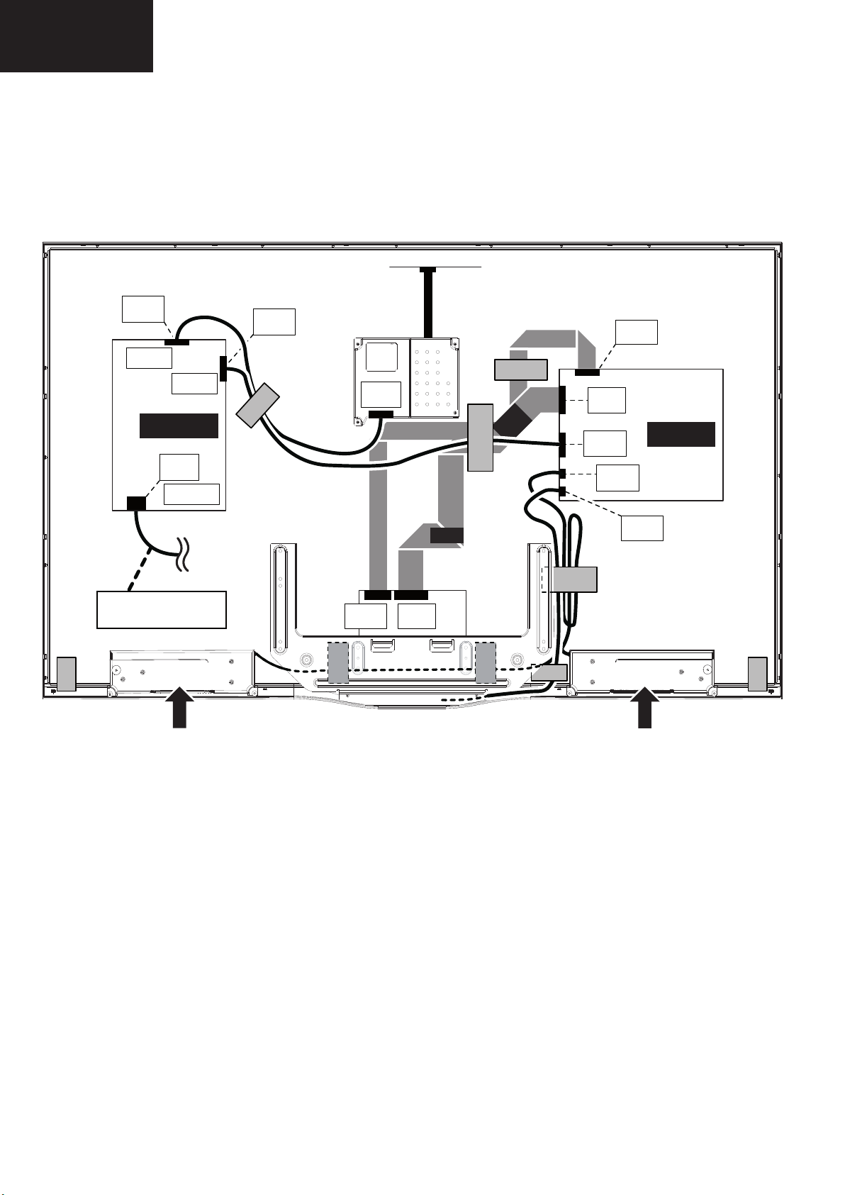
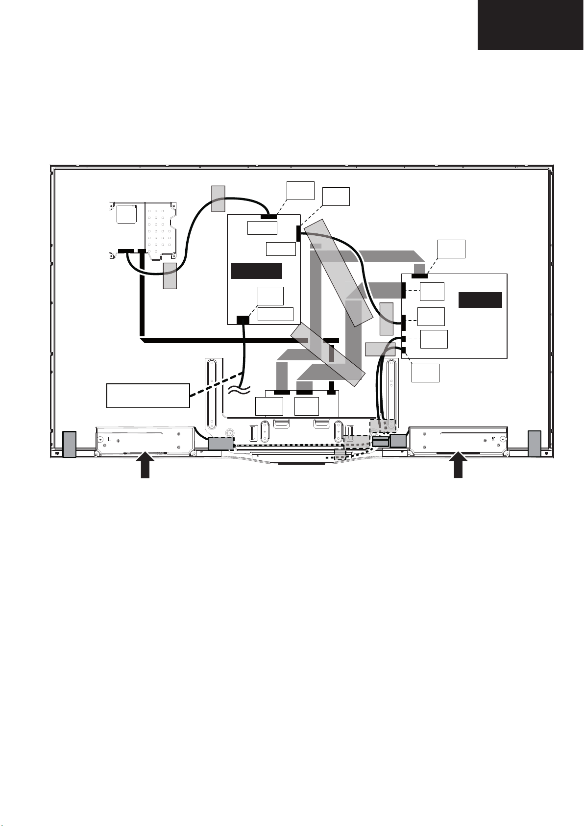
LC-39/50LE650
AC CORD
Power unit
P802
P801
[EL]
SC101
[LA]
[PD]
Main unit
[LV]
[PD]
[SP]
[LW]
[LA]
[RA]
[LW]
[LV]
SPEAKER -R
SPEAKER -L
LC-39/50LE651
LC-39/50LE652
1. Removing of major Parts 39” (Continued)
1.3. Disconnect all the connectors from all the PWBs.
24
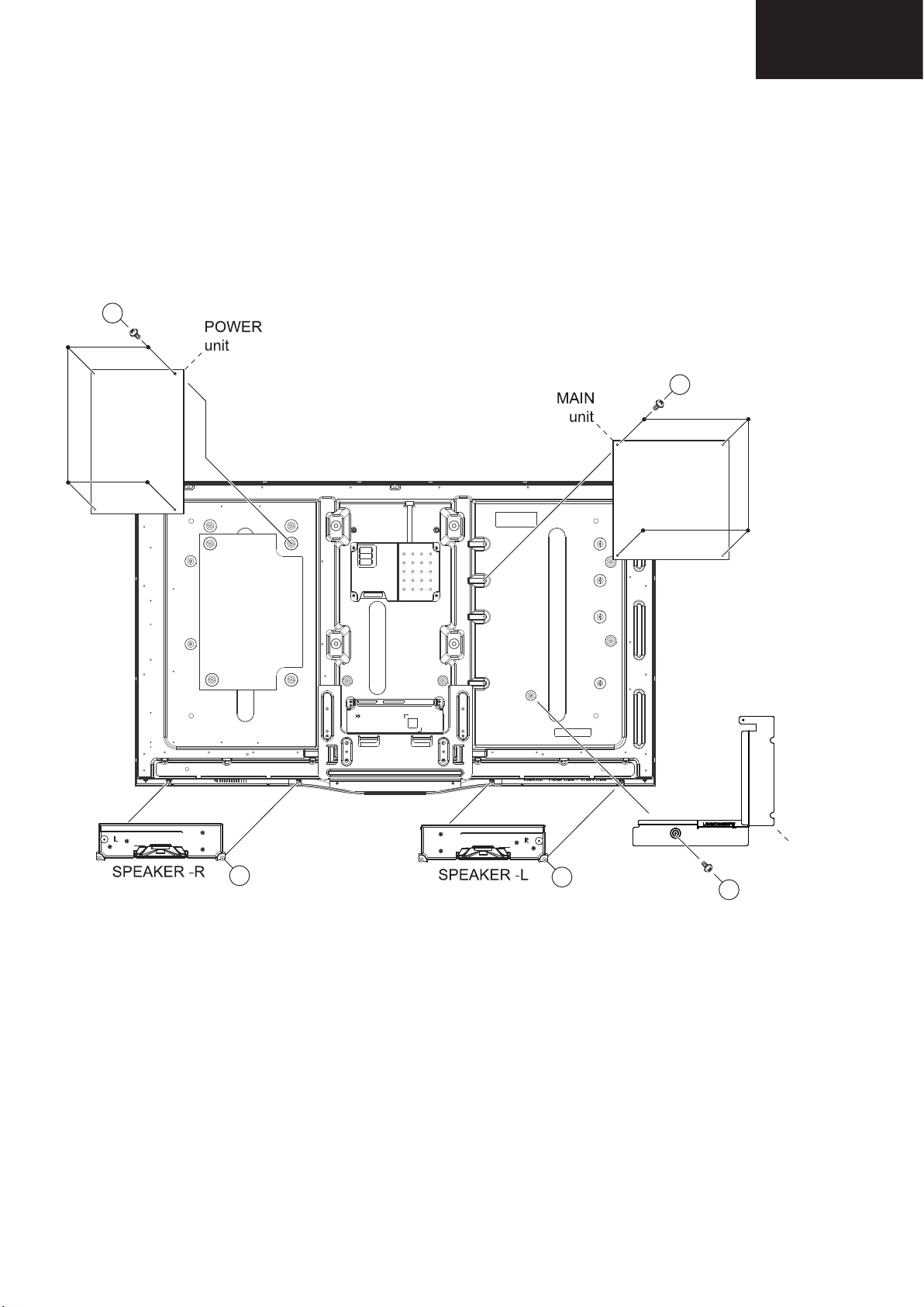
1. Removing of major Parts 39” (Continued)
LC-39LE750
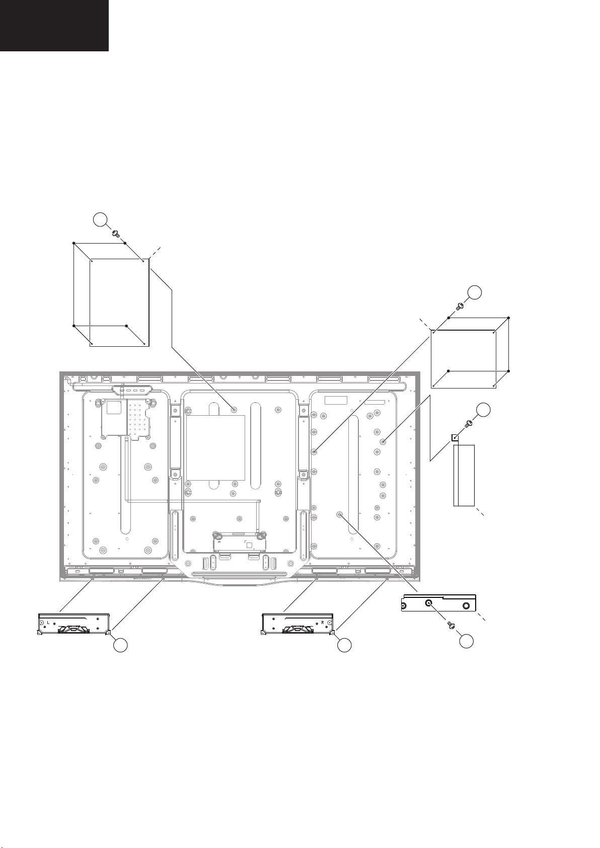
4. Remove the 4 lock screws and detach the POWER unit.
5. Remove the 4 lock screws and detach the MAIN unit.
6. Remove the 1 lock screws and detach the terminal BRACKET.
7. Remove the SPEAKER-L and SPEAKER -R .
7
8
6
5
9
1.4. Remove the 4 lock screws and detach the POWER unit.
1.5. Remove the 4 lock screws and detach the MAIN unit.
1.6. Remove the 1 lock screw and detach the terminal BRACKET.
1.7. Remove the SPEAKER-L and SPEAKER-R .
5
LC-39/50LE650
LC-39/50LE651
LC-39/50LE652
6
terminal
9
8
7
BRACKET
25
LC-39/50LE650
Service Manual
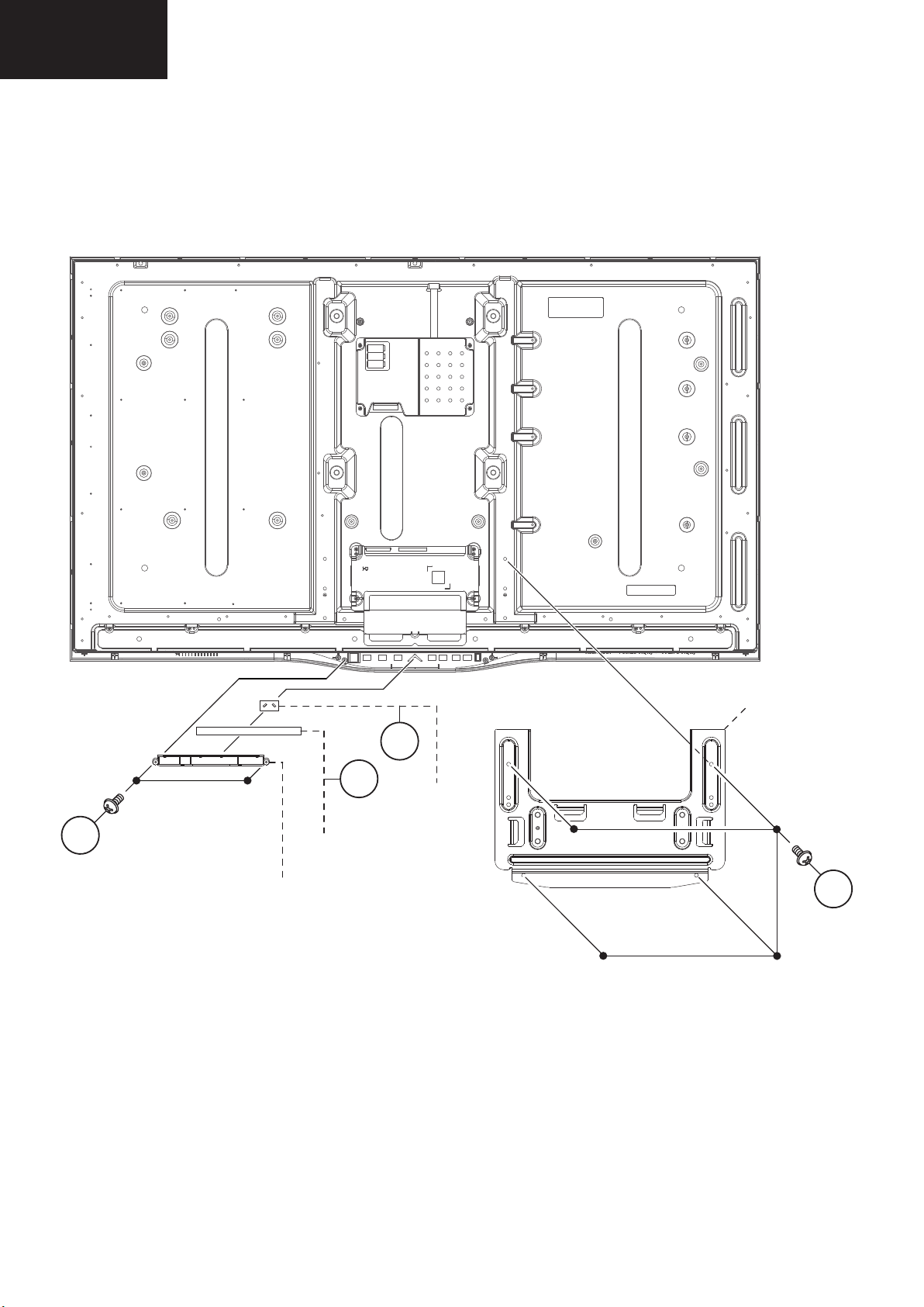
8. Remove the 4 lock screws and detach the stand BRACKET.
9. Remove the 2 lock screws and detach the control button HOLDER.
10. Detach the KEY unit and the piramid lighting DIFFUSER .
11
13
12
10
LC-39/50LE651
LC-39/50LE652
1. Removing of major Parts 39” (Continued)
1.8. Remove the 4 lock screws ⑩ and detach the stand BRACKET.
1.9. Remove the 2 lock screws ⑪ and detach the control button HOLDER.
1.10. Detach the KEY unit ⑫ and the pyramid lighting DIFFUSER ⑬.
11
control
button
HOLDER
KEY
unit
stand
BRACKET
13
12
piramid
lighting
DIFFUSER
10
26
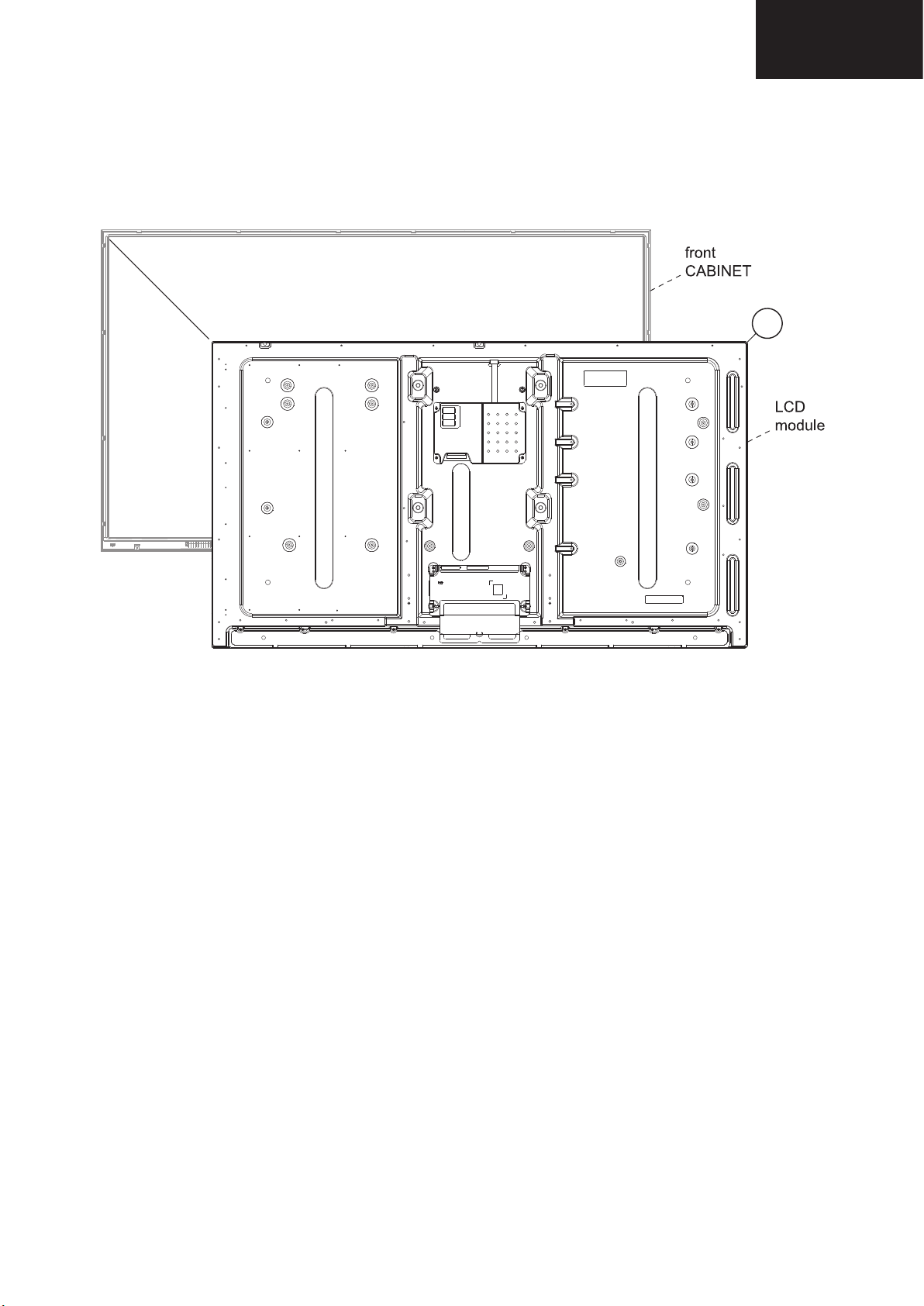
1. Removing of major Parts 39” (Continued)
LC-39LE650
14
1.11. Detach the LCD module ⑭ from the front CABINET.
LC-39/50LE650
LC-39/50LE651
LC-39/50LE652
14
27
LC-39/50LE650
LC-50LE650
LC32D44E-BK
Service Manual
CHAPTER 2. REMOVING OF MAJOR PARTS
[1] REMOVING OF MAJOR PARTS
1. Remove the 4 lock screws and detach the Stand.
2. Remove the 14 lock screws , 1 lock screw , 1 lock screw and detach the AC cord cover and the Rear Cabinet.
2
1
3
4
STAND
LC-39/50LE651
LC-39/50LE652
2. Removing of major Parts 50”
2.1. Remove the 4 lock screws and detach the Stand.
2.2. Remove the 14 lock screws , 1 lock screw , 1 lock screw and detach the AC cord cover and Rear Cabinet
rear
CABINET
2
4
3
1
STAND
1 / 5
front
CABINET
28
2. Removing of major Parts 50” (Continued)
Service Manual
2.3. Disconnect all the connectors from all the PWBs.
LC-39/50LE650
LC-39/50LE651
LC-39/50LE652
AC CORD
P802
P801
Power unit
[EL]
SC101
[LW]
[LA]
[PD]
[LV]
[LW]
[LV]
Main unit
[PD]
[SP]
[RA]
SPEAKER -R
SPEAKER -L
29
LC-39/50LE650
LC-50LE650
7
8
6
5
10
9
LC-39/50LE651
LC-39/50LE652
2. Removing of major Parts 50” (Continued)
2.4. Remove the 4 lock screws and detach the POWER unit.
2.5. Remove the 4 lock screws and detach the MAIN unit.
2.6. Remove the 1 lock screw and detach the side BRACKET.
2.7. Remove the 1 lock screw and detach the bottom BRACKET.
2.8. Remove the SPEAKER-L and SPEAKER-R .
5
POWER
unit
6
MAIN
unit
7
side
BRACKET
SPEAKER -R
bottom
BRACKET
10
SPEAKER -L
9
8
30
 Loading...