


SERVICE MANUAL
CODE : 00ZERA242USME
ELECTRONIC
CASH REGISTER
MODEL ER-A242
(U version)
CONTENTS
CHAPTER 1. SPECIFICATIONS . . . . . . . . . . . . . . . . . . . . . . . . . . . . 1
CHAPTER 2. OPTIONS . . . . . . . . . . . . . . . . . . . . . . . . . . . . . . . . . . . 5
CHAPTER 3. MASTER RESET AND PROGRAM RESET. . . . . . . . . 5
CHAPTER 4. HARDWARE DESCRIPTION . . . . . . . . . . . . . . . . . . . . 6
CHAPTER 5. TEST FUNCTION . . . . . . . . . . . . . . . . . . . . . . . . . . . . 12
CHAPTER 6. CAUTION TO BE USED WHEN CONNECTING
THE RS-232 CABLE. . . . . . . . . . . . . . . . . . . . . . . . . . 15
CHAPTER 7. CIRCUIT DIAGRAM AND PWB LAYOUT . . . . . . . . . 16
Parts marked with "!" are important for maintaining the safety of the set. Be sure to replace these parts with specified ones for maintaining the safety and performance of the set.
|
|
|
|
|
This document has been published to be used |
SHARP CORPORATION |
|
for after sales service only. |
|
The contents are subject to change without notice. |
|
|
|

CAUTIONS
THERE IS A RISK OF EXPLOSION IF THE BATTERY
IS REPLACED BY AN INCORRECT TYPE.
PROPERLY DISPOSE OF USED BATTERIES ACCORDING
TO THE INSTRUCTIONS.
ER-A242U

CHAPTER 1. SPECIFICATIONS
1. APPEARANCE
|
Front view |
|
Rear view |
|
|
Customer display (Pop-up type)
Operator display
Printer cover
Receipt paper
Power cord
Mode switch
Drawer
Keyboard
Drawer lock
RS-232C connector
 Printer
Take-up spool
|
Paper roll cradle |
|
Print roller arm |
Paper positioning |
|
guides |
||
|
||
Print roller |
|
|
release rever |
|
|
Inner cover |
|
2. RATING
|
ER-A242 |
|
|
Weight |
16.3lb (7.4kg) |
|
|
Dimensions |
13.0 (W) x 16.9 (D) x 11.0 (H) inches |
|
(330 (W) x 428 (D) x 280 (H) mm) |
|
|
Power source |
AC 120V (m 10%), 60Hz |
|
|
Power consumption |
Stand-by 7.7W, Operating 30W (max.) |
|
|
Working temperature |
0°C~40°C (32°F to 104°F) |
|
|
3. KEYBOARD
1) KEYBOARD LAYOUT
Type |
Normal keyboard |
|
|
Key position |
STD/MAX 53 |
|
|
Key pitch |
19 (W) x 19 (H) mm |
|
|
Key layout |
Fixed type |
|
|
2) KEY LIST
■Keyboard layout
■Key names
KEY TOP |
DESCRIPTION |
|
|
2 |
Paper feed key |
|
|
RA |
Received-on account key |
|
|
RCPT/PO |
After receipt issue key/Paid out key |
|
|
VOID |
Void key |
|
|
ESC |
Error escape key |
|
|
CONV |
Exchange (Currency Conversion) |
|
|
%1, %2 |
Percent 1 and 2 key |
|
|
RFND |
Refund key |
|
|
- |
Markdown key |
|
|
@/FOR |
Multiplication key |
|
|
• |
Decimal point key |
|
|
CL |
Clear key |
|
|
0-9,00 |
Numeric Keys |
|
|
PLU/SUB |
PLU code entry key |
|
|
DEPT# |
Department code entry key |
|
|
DEPT SHIFT |
Department shift key |
|
|
CLK# |
Clerk code entry key |
|
|
Dept1-32 |
Department 1- 32 keys |
|
|
TAX |
Manual tax key |
|
|
Tax 1 SHIFT |
Tax 1 shift key |
|
|
Tax 2 SHIFT |
Tax 2 shift key |
|
|
AUTO |
Automatic entry key |
|
|
CHK |
Check key |
|
|
CH |
Charge key |
|
|
MDSE SBTL |
Merchandise subtotal key |
|
|
#/TM/SBTL |
Non-add code/Time/Subtotal key |
|
|
CA/AT/NS |
Cash/Amount tender/Non Sales key |
|
|
4. MODE SWITCH
1) LAYOUT
• Rotary type
MA |
|
Manager key (MA) |
|
|
|
||
OP |
|
MA |
|
|
REG |
||
OPX/Z |
|
||
MGR |
|
||
|
|
||
OFF |
X1/Z1 |
Operator key (OP) |
|
VOID |
X2/Z2 |
||
|
|||
PGM |
|
OP |
|
|
|
|
CONV |
@/FOR |
• |
CL |
PLU |
DEPT |
DEPT |
CLK# |
TAX |
AUTO |
||||
|
/SUB |
|
# |
SHIFT |
||||||||||
|
|
|
|
|
|
A |
|
F |
|
K |
|
P |
U |
X |
RA |
%1 |
7 |
8 |
9 |
|
20 |
|
24 |
|
28 |
|
32 |
TAX1 |
TAX2 |
4 |
|
8 |
|
12 |
|
16 |
|
SHIFT |
SHIFT |
|||||
|
|
|
|
|
B |
G |
L |
Q |
V |
Y |
||||
RCPT |
%2 |
4 |
5 |
6 |
|
19 |
|
23 |
|
27 |
|
31 |
CHK |
CH |
/PO |
3 |
|
7 |
|
11 M |
15 |
|
|||||||
– |
NUMBER |
|
|
|
C |
H |
R |
W |
Z |
|||||
VOID RFND |
1 |
2 |
3 |
|
18 |
|
22 |
|
26 |
|
30 |
MDSE |
#/TM |
|
2 |
|
6 |
|
10 |
|
14 |
|
|||||||
DC |
SHIFT |
D |
I |
N |
S |
SBTL |
SBTL |
|||||||
ESC |
|
|
0 |
00 |
|
17 |
|
21 |
|
25 |
|
29 |
CA/AT/NS |
|
|
|
1 |
E |
5 |
J |
9 |
O |
13 |
T |
|||||
BS |
SPACE |
|
|
|
|
|
||||||||
Note: The small characters on the bottom or lower right in each key indicates functions or characters which can be used for character entries for text programming.
The mode switch can be operated by inserting one of the two supplied mode keys - manager (MA) and operator (OP) keys. These keys can be inserted or removed only in the “REG” or “OFF” position.
ER-A242U SPECIFICATIONS
– 1 –
The mode switch has these settings:
OFF: This mode locks all register operations. (AC power turns off.) No change occurs to register data.
Operator display |
Customer display (Pop-up type) |
||||
|
PLU/SUB |
|
|||
|
|
|
|
|
Clerk code |
|
DEPT REPEAT |
||||
|
|
|
|
|
|
OP X/Z: To take individual clerk X |
or |
Z reports, and |
to take flash |
|
|
|
|
reports. |
|
|
|
RCPT |
DC SHIFT NUMBER |
|
It can be used to toggle receipt state “ON” and “OFF” by |
|||||
|
OFF |
|
||||
|
|
|
||||
|
pressing he [RCPT/PO] key. |
|
|
|
Amount: Appears in the far-right eight (max.) positions. When the |
|
REG: |
|
|
|
|
||
For entering sales. |
|
|
|
|
amount is negative, the minus symbol “-” appears before the |
|
PGM: |
To program various items. |
|
|
|
|
amount. |
VOID: |
Enters into the void mode. This mode allows correction after |
Number of repeats for repetitive registrations: |
||||
|
finalizing a transaction. |
|
|
|
|
The number of repeats is displayed, starting at “2” and incre- |
MGR: |
For manager’s entries. The manager can use this mode for an |
|
mental with each repeat. When you have registered ten |
|||
|
override entry. |
|
|
|
|
times, the display will show “0.” (2 3 3 ..... 9 3 0 3 1 3 2 ... ) |
X1/Z1: To take the X/Z report for various daily totals.
X2/Z2: To take the X/Z report for periodic (weekly or monthly) consolidation.
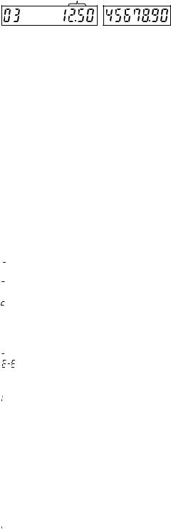
5. DISPLAY
1) OPERATOR DISPLAY
Display device: |
LED numeric display |
Number of line: |
1 line |
Number of positions: 10 positions numeric display |
|
Color of display: |
Yellow / Green |
Character form: |
7 segment + DP |
Character size: |
Numeric 14.2 (H) x 7.9 (W) mm |
Layout: |
|
0 . 1 . 2 . 3 . 4 . 5 . 6 . 7 . 8 . 9 . |
|
2) CUSTOMER DISPLAY |
|
Display device: |
LED |
Number of line: |
1 line |
Number of positions: |
7 positions |
Color of display: |
Yellow / Green |
Style: |
Pop up type |
Character form: |
7 segment + Dp |
Character size: |
14.2mm (H) x 7.9mm (W) |
Layout: |
|
3 . 4 . 5 . 6 . 7 . 8 . 9 .
Receipt function status:
The indicator “_” appears in the RCPT OFF position when the receipt function is in the OFF status.
Time: Appears in the far-right six positions (hour-minute - ”A” or hour-minute - ”P”) in the OP X/Z, REG, or MGR mode. “A” is displayed in the morning (AM), and “P” in the afternoon (PM). In the REG or MGR mode, press the [#/TM/SBTL] key to display the time.
■Machine state symbols

 : Appears during programming.
 : Appears when an error is detected.

 : Appears when the subtotal is displayed or when the amount tendered is smaller than the sales amount.
: Appears when the [CONV] key is pressed to calculate a subtotal in foreign currency.
 : Appears when a transaction is finalized by pressing the [CA/AT/ NS], [CHK] or [CH] key.
 : Appears when the change due amount is displayed.
: May appear in the far-left three positions at the timing of key entry when the electronic journal (EJ) memory is full. (Depending on programming.)
: Appears when the voltage of the installed batteries is under the required level. You must replace with new ones within two days.
 : Appears when the batteries are not installed, or the installed batteries are dead. You must replace with new ones immediately.
 : May appear right below the eighth and ninth places at the timing of finalization of a transaction when the electronic journal (EJ) memory is nearly full.
Also appears right below the tenth place when power save mode is effective.

 : Appears when the print roller arm is not locked.


 : Appears when the paper is not set or out.
ER-A242U SPECIFICATIONS
– 2 –
Segment
|
Display |
Description |
|
position |
|
|
|
|
|
|
|
Amount |
1-8 |
|
|
|
|
Minus sign |
2-10 |
-: Floating |
|
|
|
Error |
8-10 |
Exx:xx = error code |
|
|
|
PGM Mode |
10 |
P |
|
|
|
CASH, CHECK, |
10 |
F: Light up when a registration is |
CHARGE |
|
finalized by depressing CASH, |
|
|
CHECK, CHARGE key |
|
|
|
S U B T O T A L / |
10 |
o |
short tender |
|
|
|
|
|
Change |
10 |
C: Light up whenever the change |
|
|
due amount appears in the display. |
|
|
|
Currency |
10 |
c: Light up whenever the foreign |
Conversion |
|
amount appears in the display. |
|
|
|
Department |
9-10 |
No zero-suppressed |
|
|
|
PLU |
7-10 |
No zero-suppressed |
|
|
|
Repeat |
8 |
Endless count, starting from 2. |
|
|
|
Receipt OFF |
9 |
_ |
|
|
|
DC |
|
_: Double size character entry status |
|
|
|
SHIFT |
|
_: Shift character entry status |
|
|
|
NUMBER |
|
_: Number character entry status |
|
|
|
Clerk No. |
2, 3 |
-xx-: clerk number |
|
|
|
EJ FULL |
8-10 |
E-E: Light up when EJ memory is |
|
|
FULL at the timing of key entry (by |
|
|
PGM selection). |
|
|
|
Low Battery |
10 |
L: |
|
|
|
No Battery |
10 |
L: |
Decimal Point
|
Display |
Description |
|
position |
|
|
|
|
|
|
|
Decimal point |
7-1 |
|
|
|
|
TAB |
4-1 |
|
|
|
|
EJ near full |
8, 9 |
(by PGM selection) |
|
|
|
6. PRINTER
1) Printer
• Part number |
: M-T53II |
|
|
• NO. of station |
: 1 (Receipt or journal) |
||
• Validation |
: No. |
|
|
• Printing system |
: Line thermal |
|
|
• No. of dot |
: 288 dots |
|
|
• Dot pitch |
: Horizontal |
0.167mm |
|
|
Vertical |
0.167mm |
|
• Font |
: 10 dots (W) u |
24 dots (H) |
|
• Printing capacity |
: max. 24 characters/Line |
||
• Character size |
: 1.67mm (W) u |
4.17mm (H) at 10 u 24 dots |
|
• Print pitch |
: Column distance 2.0mm |
||
|
Row distance |
5.21mm |
|
• Print speed |
: Approximate 60mm/s (Approximate 12 l/s) |
||
• Paper feed speed : Approximate 60mm/s (Approximate 12 l/s) |
|||
(Manual feed) |
: Approximate 60mm/s (Approximate 12 l/s) |
||
• Reliability |
: Mechanism LIFE 6 million lines used to high- |
||
|
quality thermal paper |
||
• Paper end sensor : Set up |
|
|
|
• Cutter |
: Manual Cutter |
|
|
• Near end sensor |
: No |
|
|
2) Paper
• Paper rolldimension: 2.25 m |
0.02 inch |
|
|
|
57.5 m |
0.5mm in width |
|
|
Max. 3.15 inch |
|
|
|
Max. 30mm in diameter |
|
|
• Paper quality: |
High-quality thermal paper |
|
|
|
paper thickness: |
0.06 to 0.08mm |
|
|
Nihon seisi thermal paper |
TF50KS-E2C |
|
|
KANZAN thermal paper: |
KF50 |
|
|
KSP thermal paper: |
P350 |
|
3) Logo stamp
• No
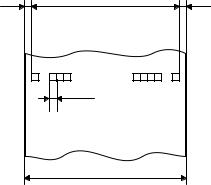
4) Printing area
Number of thermal head heater elements 288 dots
(4.75) |
48 (288 dots) |
(4.75) |
|
print area |
|
|
(max.24 characters) |
|
|
0.167 |
|
|
57.5±0.5 |
(units : mm) |
|
|
|
|
(Paper dimension) |
|
ER-A242U SPECIFICATIONS
– 3 –
7. DRAWER
[OUTLINE]
•Standard equipment: Yes (1)
•Max. number of additional drawers: 0
•The drawer consists of:
1)Drawer box (outer case) and drawer
2)Money case
3)Coin case
4)Lock (attached to the drawer)
[SPECIFICATION]
1) DRAWER BOX AND DRAWER
Model name of |
SJ423 |
||
the drawer box |
|
||
|
|
|
|
Size |
(mm) |
420 (W) x 427 (D) x 114 (H) |
|
|
|
|
|
Material |
|
Metal |
|
|
|
|
|
Bell |
|
— |
|
|
|
||
Release lever |
Standard equipment: situated at the bottom |
||
|
|
||
Drawer open |
— |
||
sensor |
|
||
|
|
||
|
|
||
Separation from |
— |
||
the main unit |
|||
|
|||
|
|
|
|
2) MONEY CASE
Separation from the drawer |
Allowed |
|
|
Separation of the bill compartments from the |
Allowed |
coin compartments |
|
|
|
Bill separator |
Allowed |
|
|
Number of compartments |
5B/6C |
|
|
Layout:
5B/6C
8. BATTERY
1) MEMORY BACK UP BATTERY
For memory back up, the dry battery AA (3 pieces) are needed.
1.Memory holding time:
Approx. 1 year after New dry batteries are installed.
2.Battery exchange method:
When the low battery symbol “L” lights up, replace the batteries (3 AA) by the following method;
1)Power on the ECR.
2)Mode switch turn to “REG” mode.
3)Remove the OLD dry batteries (3 pieces).
4)Insert the NEW dry batteries (3 pieces).
5)Confirm the low battery symbol “L” is off.
2)LOW BATTERY
Low battery indication will appear on the left side of display when the battery voltage is low.
CASE 1: When any numeric entry & any item entry is not done or just after finalization.
The machine can indicate the low battery condition. (Always)
CASE 2: When numeric entry or item entry is done.
Battery condition will not appear.
Exceptionally, when the power is restored after a power failure, the low battery condition will appear on the display only when the battery is low.
And the indicator will disappear after any key entry.
[Display sample]
“0.00”: Battery is OK.
“L 0.00”: Low battery (You have to change the batteries.)
“L 0.00”: No battery (You have to change the batteries immediately.)
After finalization
“F 12.34”: Battery is OK.
“L 12.34”: Low battery. (“L” indicate instead of “F”.)
“L 12.34”: No battery. (“L” indicate instead of “F”.)
Note: “NO BATTERY”: When the “NO BATTERY” is display, the master reset is executed at the timing of “POWER ON” after the “POWER OFF”.
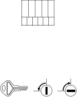
3) LOCK (LOCK KEY : LKGIM7331BHZZ)
Location of the lock: Front
Method of locking and unlocking:
To lock, insert the drawer lock key into the lock and turn it 90 degrees counter clockwise.
To unlock, insert the drawer lock key and turn it 90 degrees clockwise.
Key No: |
SK1-1 |
|
SK1-1 |
L
k oc
un
l
ck o
ER-A242U SPECIFICATIONS
– 4 –
CHAPTER 2. OPTIONS
1. |
OPTIONS (NO) |
|
|
|
|
2. |
SERVICE OPTIONS (NO) |
|
|
|
|
3. |
SUPPLIES |
|
|
|
|
|
|
|
|
|
|
|
NO |
NAME |
PARTS CODE |
PRICE |
DESCRIPTION |
|
RANK |
||||
|
|
|
|
|
|
|
|
|
|
|
|
|
1 |
Thermal roll paper |
TPAPR6656RC05 |
BA |
5 ROLLS/PACK 70 φ |
|
|
|
|
|
|
4. SPECIAL SERVICE TOOLS
NO |
NAME |
PARTS CODE |
PRICE |
DESCRIPTION |
|
RANK |
|||||
|
|
|
|
||
|
|
|
|
|
|
1 |
RS-232 Loop-back connector |
UKOG-6705RCZZ |
BC |
|
|
|
|
|
|
|
CHAPTER 3. MASTER RESET AND PROGRAM RESET
1. MASTER RESETTING
Master resetting clears the entire memory and resumes initial values.
Master resetting can be accomplished by using the following procedure:
Procedure A: 1) Plugin the AC cord to the wall outlet.
2)Set the mode switch to REG position.
3)Let the ECR be witout the memory backup battery.
4)Unplug the AC cord from the wall outlet.
5)Wait over 1 minute for discharging.
6)Plugin the AC cord to the wall outlet.
The master reset can also be accomplished in the following case.
In case power failure occurs when the machine has no battery attached to it, the master reset operation is automatically performed after the power has been restored.
(This is because if power failure occurs with no battery attached to the machine, all the memories are lost and the machine does not work properly after power recovery; this requires the master reset operation.)
2.PROGRAM RESETTING (INITIALIZATION)
This resetting resumes the initial program without clearing memory.
This resetting can be operated at below sequence in PGM mode.
Procedure: 1) |
Unplug the AC cord from the wall outlet. |
2) |
Wait over 1 muinite for discharging. |
3) |
Set the mode switch to the PGM position. |
4) |
While holding down the FEED key, plugin the AC |
|
cord to the wall outlet. |
Note: In case power failure occurs when the machine has no battery attached to it, the master reset operation is automatically performed after the power has been restored.
ER-A242U OPTIONS
– 5 –

CHAPTER 4. HARDWARE DESCRIPTION
1. HARDWARE BLOCK DIAGRAM
POWER SUPPLY
STANDARD
DRAWER.
|
CPU |
|
|
|
|
|
Data bus |
|
|
|
ROM : 256K Byte |
Address |
RAM |
|
|
|
|
||
DRIVER , SENSOR |
RAM : 20K Byte |
bus |
128K Byte |
|
|
|
|
|
|
|
|
|
|
POPUP |
PRINTER |
|
|
Seg. DRIVER |
|
|
|
|
FRONT |
|
M-T53II |
|
|
|
LED |
|
|
4 to 16 |
|
|
|
|
Dig. DRIVER |
|
|
|
|
|
|
|
|
|
DECORDER |
|
|
PAPER TAKE |
|
|
|
|
UP MOTOR |
|
|
|
|
|
|
|
KEY SCAN SIGNAL |
KEYBOARD |
|
|
|
|
MODE SWITCH |
|
|
KEY RETURN SIGNAL |
|
|
RS232C
RS232
DRIVER
ER-A242U HARDWARE DESCRIPTION
– 6 –

TRANSFORMER |
PQ1CG2032 |
V0 24V |
Drawer |
 /POFF detect point
 PQ1CG2032
 VLED 5.7V
 VCC 5V
 VDD 5V
Battery
ON/OFF Control (MODE SW)
VH, VP (8V)
LM2574
+ Tr.
 PRINTER HEAD, MOTOR
PAPER TAKEUP MOTOR
 ON/OFF Control (MODE SW,
/POFF, CPU P105)
2. DESCRIPTION OF MAIN LSI’S
2-1. CPU (M30624FGAFP)
1) Pin configuration
|
|
P97 |
VDD |
VDD |
TH |
GND |
P101 |
Vref |
P103 |
P104 |
P105 |
LATCH |
DTS |
D0 |
D1 |
D2 |
D3 |
D4 |
D5 |
D6 |
D7 |
P10 |
P11 |
P12 |
P13 |
PH1 |
|
|
|||||||||||||||||||||||||
|
|
|
|
|
|
|
|
|
|
|
|
|
|
|
|
|
|
|
|
|
|
|
|
|
|
|
|
|
|
|
|
|
|
|
|
|
|
|
|
|
|
|
|
|
|
|
|
|
|
|
|
|
|
|
|
100 |
99 |
98 |
97 |
96 |
95 |
94 |
93 |
92 |
91 |
90 |
89 |
88 |
87 |
86 |
85 |
84 |
83 |
82 |
81 |
80 |
79 |
78 |
77 |
76 |
|
|
|||||||||||||||||||||||||
|
|
SIN4 |
AVCC |
VREF |
AN0 |
AVSS |
AN1 |
AN2 |
AN3 |
AN4 |
AN5 |
AN6 |
AN7 |
D0 |
D1 |
D2 |
D3 |
D4 |
D5 |
D6 |
D7 |
D8 |
D9 |
D10 |
D11 |
D12 |
|
|
|||||||||||||||||||||||||
P96 |
|
1 |
|
SOUT4 |
|
|
|
|
|
|
|
|
|
|
|
|
|
|
|
|
|
|
|
|
|
|
|
|
|
|
|
|
|
|
|
|
|
|
|
|
D13 |
75 |
|
PH2 |
|||||||||
|
|
|
|
|
|
|
|
|
|
|
|
|
|
|
|
|
|
|
|
|
|
|
|
|
|
|
|
|
|
|
|
|
|
|
|
|
|
||||||||||||||||
P95 |
|
2 |
|
CLK4 |
|
|
|
|
|
|
|
|
|
|
|
|
|
|
|
|
|
|
|
|
|
|
|
|
|
|
|
|
|
|
|
|
|
|
|
|
|
|
D14 |
74 |
|
PH3 |
|||||||
|
|
|
|
|
|
|
|
|
|
|
|
|
|
|
|
|
|
|
|
|
|
|
|
|
|
|
|
|
|
|
|
|
|
|
|
|
|
|
|
||||||||||||||
P94 |
|
3 |
|
TB4IN |
|
|
|
|
|
|
|
|
|
|
|
|
|
|
|
|
|
|
|
|
|
|
|
|
|
|
|
|
|
|
|
|
|
|
|
|
D15 |
73 |
|
PH4 |
|||||||||
|
|
|
|
|
|
|
|
|
|
|
|
|
|
|
|
|
|
|
|
|
|
|
|
|
|
|
|
|
|
|
|
|
|
|
|
|
|
||||||||||||||||
P93 |
|
4 |
|
TB3IN |
|
|
|
|
|
|
|
|
|
|
|
|
|
|
|
|
|
|
|
|
|
|
|
|
|
|
|
|
|
|
|
|
|
|
|
|
|
|
A0 |
72 |
|
A0 |
|||||||
|
|
|
|
|
|
|
|
|
|
|
|
|
|
|
|
|
|
|
|
|
|
|
|
|
|
|
|
|
|
|
|
|
|
|
|
|
|
|
|
||||||||||||||
P92 |
|
5 |
|
SOUT3 |
|
|
|
|
|
|
|
|
|
|
|
|
|
|
|
|
|
|
|
|
|
|
|
|
|
|
|
|
|
|
|
|
|
|
|
|
|
|
A1 |
71 |
|
A1 |
|||||||
|
|
|
|
|
|
|
|
|
|
|
|
|
|
|
|
|
|
|
|
|
|
|
|
|
|
|
|
|
|
|
|
|
|
|
|
|
|
|
|
||||||||||||||
P91 |
|
6 |
|
SIN3 |
|
|
|
|
|
|
|
|
|
|
|
|
|
|
|
|
|
|
|
|
|
|
|
|
|
|
|
|
|
|
|
|
|
|
|
|
|
|
|
|
A2 |
70 |
|
A2 |
|||||
|
|
|
|
|
|
|
|
|
|
|
|
|
|
|
|
|
|
|
|
|
|
|
|
|
|
|
|
|
|
|
|
|
|
|
|
|
|
|
|
|
|
||||||||||||
P90 |
|
7 |
|
CLK3 |
|
|
|
|
|
|
|
|
|
|
|
|
|
|
|
|
|
|
|
|
|
|
|
|
|
|
|
|
|
|
|
|
|
|
|
|
|
|
|
|
A3 |
69 |
|
A3 |
|||||
|
|
|
|
|
|
|
|
|
|
|
|
|
|
|
|
|
|
|
|
|
|
|
|
|
|
|
|
|
|
|
|
|
|
|
|
|
|
|
|
|
|
||||||||||||
VDD |
|
8 |
|
BYTE |
|
|
|
|
|
|
|
|
|
|
|
|
|
|
|
|
|
|
|
|
|
|
|
|
|
|
|
|
|
|
|
|
|
|
|
|
|
|
|
|
A4 |
68 |
|
A4 |
|||||
|
|
|
|
|
|
|
|
|
|
|
|
|
|
|
|
|
|
|
|
|
|
|
|
|
|
|
|
|
|
|
|
|
|
|
|
|
|
|
|
|
|
||||||||||||
GND |
|
9 |
|
CNVss |
|
|
|
|
|
|
|
|
|
|
|
|
|
|
|
|
|
|
|
|
|
|
|
|
|
|
|
|
|
|
|
|
|
|
|
|
|
|
A5 |
67 |
|
A5 |
|||||||
|
|
|
|
|
|
|
|
|
|
|
|
|
|
|
|
|
|
|
|
|
|
|
|
|
|
|
|
|
|
|
|
|
|
|
|
|
|
|
|
||||||||||||||
XCIN |
|
10 |
|
XCIN |
|
|
|
|
|
|
|
|
|
|
|
|
|
|
|
|
|
|
|
|
|
|
|
|
|
|
|
|
|
|
|
|
|
|
|
|
|
|
|
|
A6 |
66 |
|
A6 |
|||||
|
|
|
|
|
|
|
|
|
|
|
|
|
|
|
|
|
|
|
|
|
|
|
|
|
|
|
|
|
|
|
|
|
|
|
|
|
|
|
|
|
|
||||||||||||
XCOUT |
|
11 |
|
XCOUT |
|
|
|
|
|
|
|
|
|
|
|
|
|
|
|
|
|
|
|
|
|
|
|
|
|
|
|
|
|
|
|
|
|
|
|
|
|
|
A7 |
65 |
|
A7 |
|||||||
|
|
|
|
|
|
|
|
|
|
|
|
|
|
|
|
|
|
|
|
|
|
|
|
|
|
|
|
|
|
|
|
|
|
|
|
|
|
|
|
||||||||||||||
/RESET |
|
12 |
|
/RESET |
|
|
|
|
|
|
|
|
|
|
|
|
|
|
|
|
|
|
|
|
|
|
|
|
|
|
|
|
|
|
|
|
|
|
|
|
VSS |
64 |
|
GND |
|||||||||
|
|
|
|
|
|
|
|
|
|
|
|
|
|
|
|
|
|
|
|
|
|
|
|
|
|
|
|
|
|
|
|
|
|
|
|
|
|
||||||||||||||||
XOUT |
|
13 |
|
XOUT |
|
|
|
|
|
|
|
|
M30624FGAFP |
|
|
|
|
|
|
|
|
|
|
|
|
A8 |
63 |
|
A8 |
||||||||||||||||||||||||
|
|
|
|
|
|
|
|
|
|
|
|
|
|
|
|
|
|
|
|
|
|
||||||||||||||||||||||||||||||||
GND |
|
14 |
|
Vss |
|
|
|
|
|
|
|
|
|
|
|
|
|
|
|
|
|
|
|
|
VCC |
62 |
|
VDD |
|||||||||||||||||||||||||
|
|
|
|
|
|
|
|
|
|
|
|
|
|
|
|
|
|
|
|
|
|
||||||||||||||||||||||||||||||||
XIN |
|
15 |
|
XIN |
|
|
|
|
|
|
|
|
|
|
|
|
|
|
|
|
|
|
|
|
|
|
|
|
|
|
|
|
|
|
|
|
|
|
|
|
|
|
|
|
A9 |
61 |
|
A9 |
|||||
|
|
|
|
|
|
|
|
|
|
|
|
|
|
|
|
|
|
|
|
|
|
|
|
|
|
|
|
|
|
|
|
|
|
|
|
|
|
|
|
|
|
||||||||||||
VDD |
|
16 |
|
Vcc |
|
|
|
|
|
|
|
|
|
|
|
|
|
|
|
|
|
|
|
|
|
|
|
|
|
|
|
|
|
|
|
|
|
|
|
|
|
|
|
A10 |
60 |
|
A10 |
||||||
|
|
|
|
|
|
|
|
|
|
|
|
|
|
|
|
|
|
|
|
|
|
|
|
|
|
|
|
|
|
|
|
|
|
|
|
|
|
|
|
||||||||||||||
VDD |
|
17 |
|
NMI |
|
|
|
|
|
|
|
|
|
|
|
|
|
|
|
|
|
|
|
|
|
|
|
|
|
|
|
|
|
|
|
|
|
|
|
|
|
|
|
A11 |
50 |
|
A11 |
||||||
|
|
|
|
|
|
|
|
|
|
|
|
|
|
|
|
|
|
|
|
|
|
|
|
|
|
|
|
|
|
|
|
|
|
|
|
|
|
|
|
||||||||||||||
CTCRL |
|
18 |
|
INT2 |
|
|
|
|
|
|
|
|
|
|
|
|
|
|
|
|
|
|
|
|
|
|
|
|
|
|
|
|
|
|
|
|
|
|
|
|
|
|
|
A12 |
58 |
|
A12 |
||||||
|
|
|
|
|
|
|
|
|
|
|
|
|
|
|
|
|
|
|
|
|
|
|
|
|
|
|
|
|
|
|
|
|
|
|
|
|
|
|
|
||||||||||||||
/FRDY |
|
19 |
|
INT1 |
|
|
|
|
|
|
|
|
|
|
|
|
|
|
|
|
|
|
|
|
|
|
|
|
|
|
|
|
|
|
|
|
|
|
|
|
|
|
|
A13 |
57 |
|
A13 |
||||||
|
|
|
|
|
|
|
|
|
|
|
|
|
|
|
|
|
|
|
|
|
|
|
|
|
|
|
|
|
|
|
|
|
|
|
|
|
|
|
|
||||||||||||||
P-OFF |
|
20 |
|
INT0 |
|
|
|
|
|
|
|
|
|
|
|
|
|
|
|
|
|
|
|
|
|
|
|
|
|
|
|
|
|
|
|
|
|
|
|
|
|
|
|
A14 |
56 |
|
A14 |
||||||
|
|
|
|
|
|
|
|
|
|
|
|
|
|
|
|
|
|
|
|
|
|
|
|
|
|
|
|
|
|
|
|
|
|
|
|
|
|
|
|
||||||||||||||
MOTOR |
|
21 |
|
TA4IN/U |
|
|
|
|
|
|
|
|
|
|
|
|
|
|
|
|
|
|
|
|
|
|
|
|
|
|
|
|
|
|
|
|
|
|
|
A15 |
55 |
|
A15 |
||||||||||
|
|
|
|
|
|
|
|
|
|
|
|
|
|
|
|
|
|
|
|
|
|
|
|
|
|
|
|
|
|
|
|
|
|
|
|
||||||||||||||||||
BUZ1 |
|
22 |
|
TA4OUT/U |
|
|
|
|
|
|
|
|
|
|
|
|
|
|
|
|
|
|
|
|
|
|
|
|
|
|
|
|
|
|
|
|
|
A16 |
54 |
|
A16 |
||||||||||||
|
|
|
|
|
|
|
|
|
|
|
|
|
|
|
|
|
|
|
|
|
|
|
|
|
|
|
|
|
|
|
|
|
|
||||||||||||||||||||
P77 |
|
23 |
|
TB3IN |
|
|
|
|
|
|
|
|
|
|
|
|
|
|
|
|
|
|
|
|
|
|
|
|
|
|
|
|
|
|
|
|
|
|
|
|
|
A17 |
53 |
|
A17 |
||||||||
|
|
|
|
|
|
|
|
|
|
|
|
|
|
|
|
|
|
|
|
|
|
|
|
|
|
|
|
|
|
|
|
|
|
|
|
|
|
||||||||||||||||
P76 |
|
24 |
|
TBEOUT |
|
|
|
|
|
|
|
|
|
|
|
|
|
|
|
|
|
|
|
|
|
|
|
|
|
|
|
|
|
|
|
|
|
|
|
A18 |
52 |
|
NC |
||||||||||
|
|
|
|
|
|
|
|
|
|
|
|
|
|
|
|
|
|
|
|
|
|
|
|
|
|
|
|
|
|
|
|
|
|
|
|
||||||||||||||||||
P75 |
|
25 |
|
TA2INW |
|
|
|
|
|
|
|
|
|
|
|
|
|
|
|
|
|
|
|
|
|
|
|
|
|
|
|
|
|
|
|
|
|
|
|
|
|
A19 |
51 |
|
NC |
||||||||
|
|
|
|
|
|
|
|
|
|
|
|
|
|
|
|
|
|
|
|
|
|
|
|
|
|
|
|
|
|
|
|
|
|
|
|
|
|
||||||||||||||||
|
|
TA2OUTW |
TA1IN/V |
TA1OUT/V |
TB5IN |
TB5OUT |
TXD1 |
RXD1 |
CLK1 |
CLKS1 |
TXD0 |
RXD0 |
CLK0 |
/RTS0 |
/RDY |
ALE |
/HOLD |
/HLDA |
CBCLK |
/RD |
/BHE |
/WR |
/CS3 |
/CS2 |
/CS1 |
/CS0 |
|
|
|||||||||||||||||||||||||
|
|
26 |
27 |
28 |
29 |
30 |
31 |
32 |
33 |
34 |
35 |
36 |
37 |
38 |
39 |
40 |
41 |
42 |
43 |
44 |
45 |
46 |
47 |
48 |
49 |
50 |
|
|
|||||||||||||||||||||||||
|
|
|
|
|
|
|
|
|
|
|
|
|
|
|
|
|
|
|
|
|
|
|
|
|
|
|
|
|
|
|
|
|
|
|
|
|
|
|
|
|
|
|
|
|
|
|
|
|
|
|
|
|
|
|
|
|
|
|
|
|
|
|
|
|
|
|
|
|
|
|
|
|
|
|
|
|
|
|
|
|
|
|
|
|
|
|
|
|
|
|
|
|
|
|
|
|
|
|
|
|
|
|
|
|
|
|
|
|
|
P74 |
P73 |
CLK |
P71 |
DAT |
P67 |
P66 |
/FRES |
P64 |
FSD |
FRD |
FSCK |
DR1 |
/RDY |
/HOLD |
VCC |
NC |
NC |
/RD |
NC |
/WR |
/CS3 |
/RAS1 |
BUSY |
/ROS1 |
|
|
|||||||||||||||||||||||||
2) Pin description
Pin |
SYMBOL |
SIGNAL |
In/ |
Function |
|
No. |
NAME |
Out |
|||
|
|
||||
|
|
|
|
|
|
1 |
SOUT4 |
P96 |
In |
Key IN |
|
|
|
|
|
|
|
2 |
CLK4 |
P95 |
In |
Key IN |
|
|
|
|
|
|
|
3 |
TB4IN |
P94 |
In |
Key IN |
|
|
|
|
|
|
|
4 |
TB3IN |
P93 |
In |
Key IN |
|
|
|
|
|
|
|
5 |
SOUT3 |
P92 |
In |
Key IN |
|
|
|
|
|
|
|
6 |
SIN3 |
P91 |
In |
Key IN |
|
|
|
|
|
|
|
7 |
CLK3 |
P90 |
In |
Key IN |
|
|
|
|
|
|
|
8 |
BYTE |
VDD |
In |
VDD |
|
|
|
|
|
|
|
9 |
CNVss |
CNVss |
In |
Normal : L Booting : H |
|
|
|
|
|
|
|
10 |
XCIN |
XCIN |
In |
Calender clock :32.768KHz |
|
|
|
|
|
|
|
11 |
XCOUT |
XCOUT |
In |
Calender clock :32.768KHz |
|
|
|
|
|
|
|
12 |
/RESET |
/RESET |
In |
Reset |
|
|
|
|
|
|
|
13 |
XOUT |
XOUT |
Out |
Open |
|
|
|
|
|
|
|
14 |
Vss |
Vss |
In |
Vss |
|
|
|
|
|
|
|
15 |
XIN |
XIN |
In |
System clock |
|
|
|
|
|
|
|
16 |
Vcc |
VDD |
In |
VDD |
|
|
|
|
|
|
|
17 |
NMI |
P85 |
In |
Not used |
|
|
|
|
|
|
|
18 |
INT2 |
P84 |
Out |
PRINTER/STB2 |
|
|
|
|
|
|
|
19 |
INT1 |
/RDY |
In |
NU FMC (/RDY) |
|
|
|
|
|
|
|
20 |
INT0 |
P-OFF |
In |
Power off |
|
|
|
|
|
|
|
21 |
TA4IN/U |
MOTOR |
Out |
Paper take up motor drive |
|
|
|
|
|
|
|
22 |
TA4OUT/U |
BUZ1 |
Out |
Buzzer drive |
|
|
|
|
|
|
|
23 |
TB3IN |
P77 |
In |
RS232 :DR |
|
|
|
|
|
|
|
24 |
TBEOUT |
P76 |
In |
RS232 :CS |
|
|
|
|
|
|
|
25 |
TA2INW |
P75 |
In |
RS232 :CD |
|
|
|
|
|
|
|
26 |
TA2OUTW |
P74 |
Out |
RS232 :ES |
|
|
|
|
|
|
|
27 |
TA1IN/V |
P73 |
Out |
Drawer drive 2 |
|
|
|
|
|
|
|
28 |
TA1OUT/V |
CLK2 |
Out |
Printer data clock |
|
|
|
|
|
|
|
29 |
TB5IN |
P71 |
Out |
NU FMC (BUSY) |
|
|
|
|
|
|
|
30 |
TB5OUT |
TXD2 |
Out |
Print data |
|
|
|
|
|
|
|
31 |
TXD1 |
P67 |
Out |
RS232 :SD |
|
|
|
|
|
|
|
32 |
RXD1 |
P66 |
In |
RS232 :RD |
|
|
|
|
|
|
|
33 |
CLK1 |
/FRES |
Out |
NU FMC (/FRES) |
|
|
|
|
|
|
|
34 |
CTS1/RTS1 |
P64 |
Out |
RS232 :RS |
|
|
|
|
|
|
|
35 |
TXD0 |
FSD |
Out |
FMC :Send data |
|
|
|
|
|
|
|
36 |
RXD0 |
FRD |
In |
FMC :Receive data |
|
|
|
|
|
|
|
37 |
CLK0 |
FSCK |
Out |
FMC :Shift clock |
|
|
|
|
|
|
|
38 |
/RTS0 |
DR1 |
Out |
Drawer drive 1 |
|
|
|
|
|
|
|
39 |
CLKOUT |
/RDY |
In |
/RDY (CGROM) |
|
|
|
|
|
|
|
40 |
ALE |
NC |
Out |
NOT USE |
|
|
|
|
|
|
|
41 |
/HOLD |
/HOLD |
In |
/BOOT MODE |
|
|
|
|
|
|
|
42 |
/HLDA |
NC |
Out |
NOT USE |
|
|
|
|
|
|
|
43 |
CBCLK |
BCLK |
Out |
BCLK |
|
|
|
|
|
|
|
44 |
/RD |
/RD |
Out |
Read |
|
|
|
|
|
|
|
45 |
/BHE |
NC |
Out |
NOT USE |
|
|
|
|
|
|
|
46 |
/WR |
/WR |
Out |
Write |
|
|
|
|
|
|
|
47 |
/CS3 |
CS3 |
Out |
Display segment latch |
|
|
|
|
|
|
|
48 |
/CS2 |
/CS2 |
Out |
Chip select :for RAM |
|
|
|
|
|
|
|
49 |
/CS1 |
/CS1 |
Out |
EPM Control |
|
|
|
|
|
|
|
50 |
/CS0 |
/CS0 |
Out |
Chip select : for ROM |
|
|
|
|
|
|
|
51 |
A19 |
A19 |
Out |
Address bus :19 |
|
|
|
|
|
|
|
52 |
A18 |
A18 |
Out |
Address bus :18 |
|
|
|
|
|
|
ER-A242U HARDWARE DESCRIPTION
– 7 –
 Loading...