


Dealer Knowledge Book
MODELER-A410/ER-A420
PC Link Setup Utility for
ROM Version RACC1A
Category |
Contents |
Pg |
|
Section 1. |
Overview……………………………………………….……………….……… |
2 |
|
Section 2. |
Prior to Beginning ……..…………………………………….………..……… |
3 |
|
Section 3. |
Cable Requirements…………………………………..……………………… |
3 |
|
ER-A410/ER-A420 Setup …………………………...………………………. |
5 |
||
Section 4. |
PC Hardware & Software Requirements ………………………………….. |
7 |
|
Section 5. |
PC Link Installation ……………………………………………….………….. |
8 |
|
Section 6. |
PC Link Communications Settings ……………….………………………… |
13 |
|
Section 7. |
Starting Initial Programming ………………………………………………… |
15 |
|
Section 8. |
Modifying Current Programming Data ……………………….…………….. |
52 |
|
Section 9. |
Downloading a Graphics Logo ……………………………….…………….. |
58 |
|
Section 10. |
Trouble Shooting & Error Messages ……………………………………….. |
65 |
|
Notice:
The PC Link software and/or documentation referred to in this manual are furnished under license by Sharp Electronics Corporation and may only be used or copied in accordance with the terms of such license.
Except as permitted by such license, no part of the software or documentation may be reproduced, stored in a retrieval system, or transmitted, in any form or by any means, electronic, mechanical, recording, or otherwise, without the prior written permission of Sharp Electronics Corporation.
Designs and specifications are subject to change without notice.

PC Link
TRADEMARKS
PC Link and Easy Programming Tool are trademarks of Sharp Corporation, Microsoft,
Windows, Windows 98SE, Windows 2000 and Win32 are trademarks of Microsoft
Corporation. All other trademarks and registered marks are the property of their respective holders.
NOTICE TO USERS
This manual is intended to assist authorized Sharp dealers, with learning and understanding how to install and provide support in the utilization of the PC Link software utility for the ER-A410 and ER-A420 model cash registers. This assumes that you are familiar with the general programming concepts of the ER-A410 and ER-A420. Please read this introductory section carefully as it will provide helpful hints and recommendations that will make your time more efficient and produce time saving results. This manual is not intended for end user customers of authorized Sharp dealers.
Designs and specifications are subject to change without notice.
Page 1

PC Link
Section-1: Overview
The Easy Programming Tool is a PC-based utility designed to assist you with the setup tasks associated with the ERA410 and ERA420 model cash registers.
There are three basic functions provided by the PC Link utilities:
1 – Programming of preset data
2 – Graphic Logo image downloading
3 – All RAM Upload (storage) and Download (recovery)
Please refer to the chart below for the available programming options:
SRV-Mode Related Jobs: (X = indication of availability)
|
Job No. |
Description |
Yes |
No |
|
|
900 |
System Presets |
X |
|
|
|
950 |
Free Key – Function keys |
|
X |
|
|
951 |
Free Key – Direct Keys (Dept. & PLU) |
|
X |
|
|
975 |
Memory Allocation |
|
X |
|
|
930-939 |
Z-Counters |
X |
|
|
|
942-969 |
GT and Training GT |
X |
|
|
|
944 |
PGM-2 Secret Code |
X |
|
|
|
989 |
Memory Initial |
|
X |
|
|
|
|
|
|
|
|
PGM 1/2-Mode Related Jobs: (X = indication of availability) |
|
|
|
|
|
Job No. |
Description |
Yes |
No |
|
|
11xx – 21xx |
Departments |
X |
|
|
|
12xx – 22xx |
PLU/Sub departments |
X |
|
|
|
13xx – 23xx |
Function keys |
X |
|
|
|
15xx – 25xx |
Cashiers |
X |
|
|
|
2119 |
Direct Key Assignment for Departments |
|
X |
|
|
2219 |
Direct Key Assignment for PLU/Sub departments |
|
X |
|
|
26xx |
Date/Time/Optional Settings |
X |
|
|
|
2690 |
Peripheral Channel Assignment |
|
X |
|
|
27xx |
Tax Rate/Tax Table Settings |
X |
|
|
|
2900 |
Auto Key Programming |
|
X |
|
|
61xx |
RS232 Options/Settings |
|
|
|
|
71xx |
CAT (Credit Authorization Terminal) Setting |
X |
|
|
|
989 |
Memory Initial |
|
X |
|
Designs and specifications are subject to change without notice.
Page 2

PC Link
Section-2: Prior to Beginning
Prior to using the PC Link setup utility, the following equipment is required:
-ER-A410/ER-A420
-Communications cable
-IBM compatible PC
1.ER-A410/ER-A420 Communications Ports:
There are two communications ports standard as shown in the illustration below.
2.Cabling Connection Charts:
Example-1: The PC has a 25-pin D-SubExample-2: PC has a 9-pin D-Sub
Designs and specifications are subject to change without notice.
Page 3

PC Link
3. ECR Connection to the PC:
Once the connection cable is made, simply select either CH-1 or CH-2 at the ECR and then connect the remaining end to the PC communications port to be used for the PC Link utility.
NOTE:
The PC Link utility uses the Online communications function and when connecting the cable to the desired channel, no other device may be assigned to the same channel.
Designs and specifications are subject to change without notice.
Page 4
PC Link
Section-3: ER-A410/ER-A420 Setup
It is recommended to establish the proper settings at the ECR prior to installing the PC Link software at the PC.
Step – 1: PGM Job#2690:Device Configuration
The ERA410/ERA420 RS232 Device Programming (2690 Option #1) must be set up to communicate with PC Link. Select the channel to be connected to the PC and program the
Device Configuration Setting accordingly:
Example-1:Assigning the Online function to Channel-1
2690 Æ . Æ @/For Æ 1 @/For Æ1000 Æ SBTL Æ CA/AT:Channel No. 1
Example-2:Assigning the Online function to Channel-2
2690 Æ . Æ @/For Æ1 @/For Æ 2000 Æ SBTL Æ CA/AT:Channel No. 2
Designs and specifications are subject to change without notice.
Page 5

PC Link
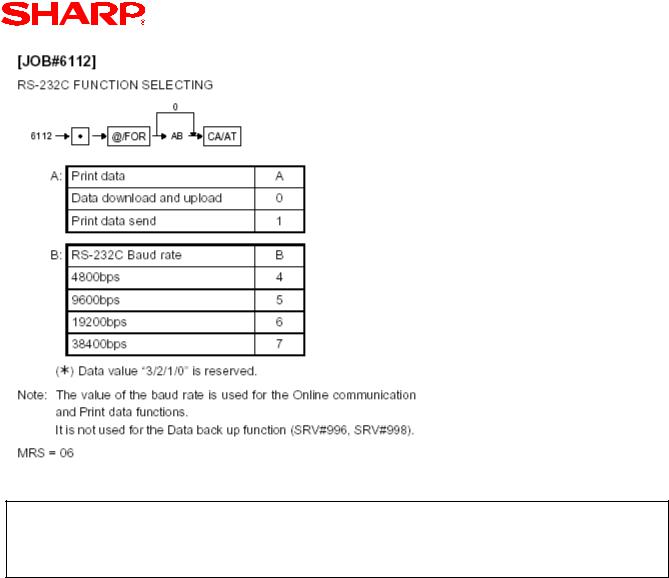
Step – 2: PGM Job#6112:
The communications baud rate must match the setting selected for the PC Link communications utility.
Since the Online communications function is used for the PC Link utility “A” = “0”. Leading zeros are not required, thus “B” is the setting variable for this programming job.
Designs and specifications are subject to change without notice.
Page 6
PC Link
Example Settings:
AB = 04 : 4800 bps
=05: 9600 bps
=06: 19200 bps
=07: 38400 bps
Designs and specifications are subject to change without notice.
Page 7

PC Link
Section-4: PC Hardware & Software Requirements
Once the PC Link utility has been installed, the minimum PC hardware and operating systems required for operations are outlined below:
• IBM PC or 100% Compatible
o24 MB DRAM for operations
o40 MB Free Hard Disk Space
•Operating System
oMicrosoft Windows 98/ME/2000/XP
•Display Setting
o1024 x 768 – avoids scrolling when using the application
Designs and specifications are subject to change without notice.
Page 8
PC Link
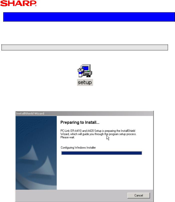
Section-5: PC Link Software Installation Procedures
The PC Link setup utility must be installed (versus copying) to facilitate communications between the ECR and the PC.
Step – 1: Start the Installation
1. Locate and Click on the Set Up Icon.
2. The following screens will be displayed during installation.
Designs and specifications are subject to change without notice.
Page 9
PC Link
3.When an older version Windows® Installer is detected: If an older version installer is detected – simply click [OK]
Click
OK
Step – 2: Follow the InstallShield Wizard Prompts
When the InstallShield Wizard appears to begin installation – click [Next] to continue.
Click
Next
Designs and specifications are subject to change without notice.
Page 10
PC Link
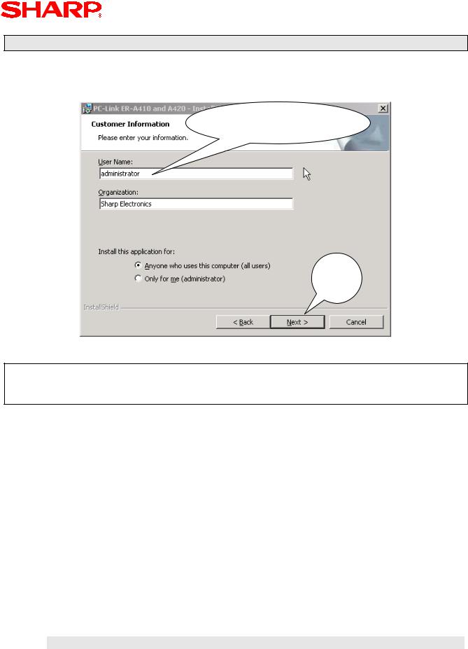
Step – 3: Enter the User Name & Organization
Provisions for entering a user name and organization are prompted. When finished you click [Next] to continue.
Enter User Name &
Organization
Click
Next
NOTE:
When installing this utility, it is recommended to allow all users for the computer to have access to the application.
Designs and specifications are subject to change without notice.
Page 11

PC Link
Designs and specifications are subject to change without notice.
Page 12

PC Link
Step – 4: Select Destination Folder
For this installation example – it is recommended that the default folder be used for installation. To accept the default settings – click [Next] to continue.
Accept Default Set Up
Click
Next
Step – 5: Review Information
Review the previously entered installation data. To accept the settings – click [Next].
Review Information
Entered
Click
Install
Designs and specifications are subject to change without notice.
Page 13
PC Link
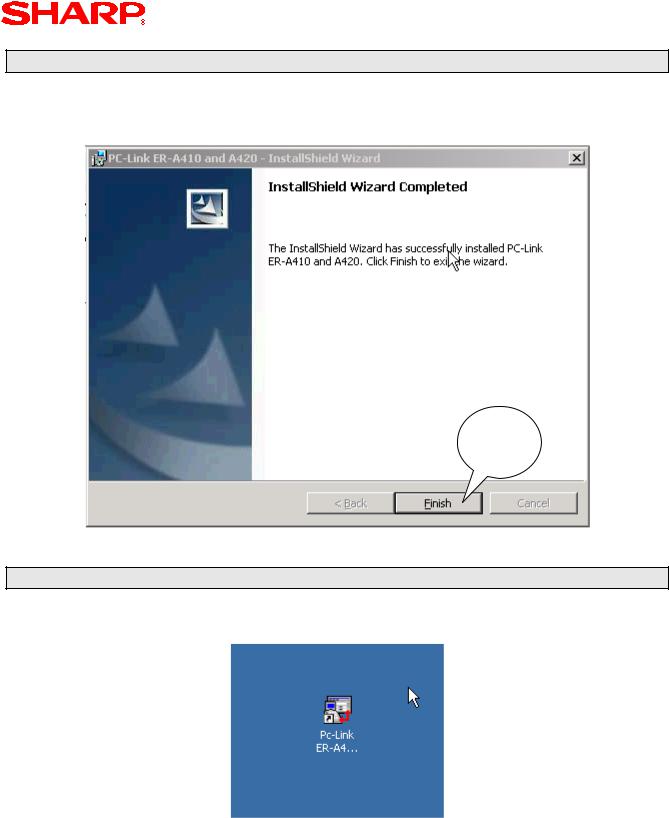
Step – 6: Complete the Installation Process
When the application has been successfully installed to complete and exit the InstallShield
Wizard – click [Finish].
Click
Finish
The PC Link icon will be on your computer desktop when the installation is done.
Step – 7: Locate the PC Link ICON
The PC Link icon will be located on your computer desktop when the installation is done.
Designs and specifications are subject to change without notice.
Page 14

PC Link
Section-6: PC Link Communications Settings
Prior to launching the PC Link utility for programming, the communications settings at the
PC must be synchronized with the ECR.
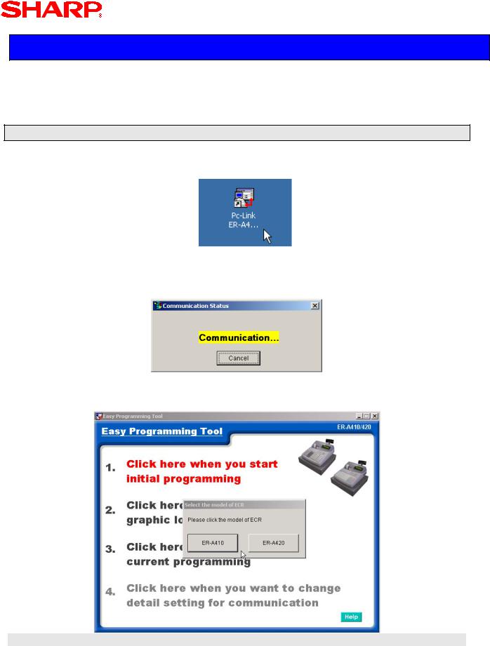
Step – 1: Launch the PC Link Utility
1.Launch the PC Link utility by double-clicking the PC Link ICON.
2.The PC Link utility automatically searches for a connected ECR – click [Cancel] to bypass this step.
Click
Cancel
NOTE:
When the ECR is not connected and enough time lapses (the no. of retries is attempted without a successful connection), the following error message will appear – to proceed with setting the PC communications setup, click [OK]
Click
OK
Designs and specifications are subject to change without notice.
Page 15

PC Link
Step – 2: Select Communications Settings
1. Select Menu Option #4 to make the desired communications selections
2.Make the required communications settings as shown below.
a.Select the correct Com Port used at the PC (Not the ECR) – Com 1 or Com 2
b.Always use Full Duplex
c.Match the PGM Job code 6112 - Baud Rate Setting
b
a
c
3. Once the desired settings are selected – click [OK]
Designs and specifications are subject to change without notice.
Page 16
PC Link
Section-7: Starting Initial Programming
Prior to launching the PC Link programming tool, insure that the ECR and the PC are connected using the cable outlined previously.
Launch the PC Link Programming Tool
1.Launch the programming tool - double-click the PC Link Icon.
2.The PC Link application will search for the connection of the ECR through the communications port – if everything is set correctly, the application will start.
3. Select Menu Option #1 - select the desired model ER-A410 or ER-A420 ECR.
Designs and specifications are subject to change without notice.
Page 17
PC Link
Initial Programming Main Menu
Overview of selections provided by the Initial Programming Main menu:
1.Help file: contains reference help for using the utility
2.[Send/Save] button: Dual function button which can save the data or send it
3.[Select] button: used to select the highlighted menu item
4.[Back] button: returns the application to the previous display
1
2
3
4
Sending/Saving Data
1.Selecting the [Send/Save] button – you will be prompted to send the changes to the
ECR.
2. To send data back to the ECR – click [Yes] or go to the next step to save on the PC.
Designs and specifications are subject to change without notice.
Page 18

PC Link
3.To save the data to the PC – click [No] and the prompt to save the data to the PC will appear.
4. To save the data to the PC - click [Yes]
NOTE:
The PC Link utility will prompt to save the data to a designated date-stamped folder
5.To save the data to the designated dated folder – click [Yes] or click [No] to name the folder
6. Name the folder – click [ok] when finished
Designs and specifications are subject to change without notice.
Page 19
PC Link
Menu Selections available from the Drop-Down Menu
Selections available from the Main Menu Drop-Down Menu option list:
NOTE:
The following examples for each available setting will relate to the above Main Menu and refer to scrolling to the Menu selection. The above list also incorporates an alpha search function to ease locating the desired Menu selection.
Designs and specifications are subject to change without notice.
Page 20
 Loading...