


FODC635UDR
Table of contents
 Loading...
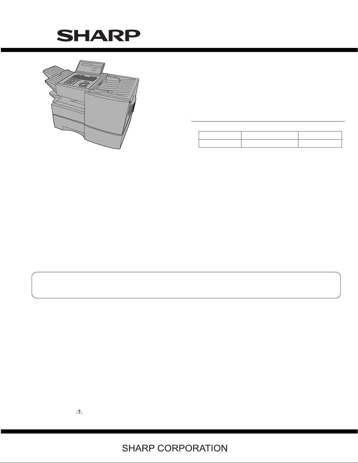
OPTION
Toner cartridge: FO-50ND
Drum cartridge: FO-47DR
Option memory: FO-8MK
Verification stamp: FO-45VS
Paper cassette (2nd): FO-CS2
LAN Network interface kit: FO-LN1
Network printer kit: FO-NP1
Network scanner kit: FO-NS2
Dual line kit: FO-60DL
NOTE:
• FO-NP1 (Network Printer Kit) and FO-60DL (Dual Line Kit) can not
be mounted simultaneously.
• FO-LN1 (LAN Network Interface Kit) and FO-60DL (Dual Line Kit)
can be mounted simultaneously. However, multi-operation of
2 line communication and network scan is not possible.
TopPage
FO-DC635U
SERVICE MANUAL
No. 00ZFDC635USME
FACSIMILE
MODEL
MODEL SELECTION CODE DESTINATION
FO-DC635 U U.S.A./Canada
Chapters 1, 2, 3, 7 and 8 of this manual are omitted because they are partly common to the FO-4470U/
FO-DC535U. Please refer to previous service manual (00ZFO4470USME) / (00ZFDC535USME) for these
chapters.
FO-DC635U
Parts marked with " " are important for maintaining the safety of the set. Be sure to replace these parts with specified ones for maintaining the
safety and performance of the set.
– 0 –
This document has been published to be used for
after sales service only.
The contents are subject to change without notice.

FO-DC635U
CHAPTER 1. GENERAL DESCRIPTION
[1] Caution........................................................... 1-1
[2] Specifications ................................................. 1-3
[3] Operation panel.............................................. 1-4
[4] Transmittable documents............................... 1-6
[5] Installation...................................................... 1-7
CHAPTER 2. ADJUSTMENTS
[1] Adjustments ................................................... 2-1
[2] Diagnostics and service soft switches............ 2-3
[3] Troubleshooting ........................................... 2-40
[4] Error code table............................................ 2-40
[5] Overseas communication mode .................. 2-40
[6] Administrator mode in the personal book
function ........................................................ 2-40
CHAPTER 3. MECHANICAL DESCRIPTION
[1] Mechanical description .................................. 3-1
[2] Printer description .......................................... 3-1
[3] Disassembly and assembly procedures........ 3-1
[4] How to install the verification stamp (FO-
45VS) ............................................................. 3-2
CONTENTS
[2] Circuit description of control PWB ................. 5-1
[3] Circuit description of CIS unit ......................5-15
[4] Circuit description of LIU PWB ....................5-16
[5] Circuit description of operation panel PWB......5-18
[6] Circuit description of power supply PWB......5-19
[7] Circuit description of Dual Line Kit (Option:
FO-60DL).....................................................5-20
CHAPTER 6. CIRCUIT SCHEMATICS AND PARTS
LAYOUT
[1] Control PWB circuit .......................................6-1
[2] LIU PWB circuit ........................................... 6-18
[3] Printer PWB circuit ......................................6-21
[4] Power Supply PWB circuit........................... 6-25
[5] Operation Panel PWB circuit .......................6-27
[6] LCD Relay PWB circuit................................6-31
[7] 1st Paper Cassette PWB circuit ..................6-32
CHAPTER 7. OPERATION FLOWCHART
[1] G3 Protocol.................................................... 7-1
[2] Super G3 Protocol ......................................... 7-1
[3] Power on sequence....................................... 7-1
CHAPTER 4. DIAGRAMS
[1] Block diagram ................................................ 4-1
[2] Wiring diagram............................................... 4-2
[3] Point-to-point diagram.................................... 4-3
CHAPTER 5. CIRCUIT DESCRIPTION
[1] Circuit description .......................................... 5-1
CHAPTER 8. OTHER
[1] Service tools .................................................. 8-1
[2] Rewriting version up the FLASH ROM ..........8-1
Parts Guide
– i –

- MEMO -
FO-DC635U
– ii –

FO-DC635U
FO-DC635U
CHAPTER 1. GENERAL DESCRIPTION
Service Manual
[1] Caution
1. Laser caution
This laser printer is a class 1 laser product that complies with 21CFR 1040.10 and 1040.11 of the CDRH or IEC60825-1 standard. This means that
this machine does not produce a hazardous laser radiation. The use of controls, adjustments or performance of procedures other than those specified
herein may result in hazardous radiation exposure.
This laser radiation is not a danger to the skin, but when an exact focusing of the laser beam is achieved on the eyes retina, there is danger of spot
damage to the retina.
The following cautions must be observed to avoid exposure of the laser beam to your eyes at the time of servicing.
1) When a problem in the laser optical unit has occurred, the whole optical unit must be exchanged as a unit, not an individual part.
2) Do not look into the machine with the main switch turned on after removing the toner/developer unit and drum cartridge.
3) Do not look into the laser beam exposure slit of the laser optical unit with the connector connected when removing and installing the optical system.
4) The cover of Laser Printer Unit contains the safety interlock switch.
Do not defeat the safety interlock by inserting wedges or other items into the switch slot.
Laser Wave Length : 770 nm -810 nm
Laser Pulse Times : 51.3 ns
Laser Output Power Max : 5 mW
2. Life of consumable
Section Part Estimated Life Replaced by
Toner cartridge Replacement cartridge
(FO-50ND)
Drum cartridge Replacement cartridge (FO-47DR) 20,000 prints (at Letter/4%
Paper feed Transfer roller (Refer to the P/G No. 10-8)
(0KW4127410302)
Fusing unit Fusing unit (Refer to the P/G No. 9-14)
(0KW4127036001)
Paper transport Paper transfer roller (Refer to the P/G No. 8-6)
(0KW4127300101)
Unit FO-DC635 5 years or 75,000 prints of
6,000 prints (at Letter/4%
chart)
chart)
50,000 prints Service Engineer
50,000 prints Service Engineer
Cleaning as needed ———————
early either
User
User
———————
1 – 1
3. Caution for Battery replacement
FO-DC635U
(Danish) ADVARSEL !
Lithiumbatteri-Eksplosionsfare ved fejlagtig håndtering.
Udskiftning må kun ske med batteri af samme fabrikat og type.
Levér det brugte batteri tilbage til leverandoren.
(English) Caution !
Danger of explosion if battery is incorrectly replaced.
Replace only with the same or equivalent type
recommended by the equipment manufacturer.
Discard used batteries according to manufacturer's instructions.
(Finnish) VAROITUS
Paristo voi räjähtää, jos se on virheellisesti asennettu.
Vaihda paristo ainoastaan laitevalmistajan suosittelemaan
tyyppiin. Hävitä käytetty paristo valmistajan ohjeiden mukaisesti.
4. Precautions for using Lead-Free Solder
1. Employing lead-free solder
This model employs lead-free solder.
This is indicated by the "LF" symbol printed on the PWB and in the service manual.
The suffix letter indicates the alloy type of the solder.
Example:
(French) ATTENTION
Il y a danger d'explosion s' il y a remplacement incorrect
de la batterie. Remplacer uniquement avec une batterie du
même type ou d'un type recommandé par le constructeur.
Mettre au rébut les batteries usagées conformément aux
instructions du fabricant.
(Swedish) VARNING
Explosionsfare vid felaktigt batteribyte.
Använd samma batterityp eller en ekvivalent
typ som rekommenderas av apparattillverkaren.
Kassera använt batteri enligt fabrikantens
instruktion.
(German) Achtung
Explosionsgefahr bei Verwendung inkorrekter Batterien.
Als Ersatzbatterien dürfen nur Batterien vom gleichen Typ oder
vom Hersteller empfohlene Batterien verwendet werden.
Entsorgung der gebrauchten Batterien nur nach den vom
Hersteller angegebenen Anweisungen.
Indicates lead-free solder of tin, silver and copper.
2. Using lead-free solder
When repairing a PWB with the "LF" symbol, only lead-free solder should be used. (Using normal tin/lead alloy solder may
result in cold soldered joints and damage to printed patterns.)
As the melting point of lead-free solder is approximately 40°C higher than tin/lead alloy solder, it is recommended that a
dedicated bit is used, and that the iron temperature is adjusted accordingly.
3. Soldering
As the melting point of lead-free solder (Sn-Ag-Cu) is higher and has poorer melting point (flow), to prevent damage to the
land of the PWB, extreme care should be taken not to leave the bit in contact with the PWB for an extended period of time.
Remove the bit as soon as a good flow is achieved.
The high content of tin in lead free solder will cause premature corrosion of the bit.
To reduce wear on the bit, reduce the temperature or turn off the iron when it is not required.
Leaving different types of solder on the bit will cause contamination of the different alloys, which will alter their
characteristics, making good soldering more difficult.
It will be necessary to clean and replace bits more often when using lead-free solder. Toreduce bit wear, care should be
taken to clean the bit thoroughly after each use.
1 – 2
FO-DC635U
[2] Specifications
1. GENERAL
Automatic dialing: Conventional Auto Dialing:
Memory size*: 16 MB (approx. 500 pages)
Modem speed: 33,600 bps (max.) with automatic fallback
Transmission time*: Approx. 2 seconds
Toner cartridge yield**:
(continuous printing,
4% page coverage, letter paper)
Drum cartridge yield**:
(continuous printing,
4% page coverage, letter paper)
Resolution: Standard: 203 x 98 lines/inch
Halftone (grayscale): 64 levels
Automatic document
feeder:
Paper capacity: 750 sheets (20 lb) (500-sheet cassette ava-
Compression scheme: MMR, MR, MH, Sharp (H2), JBIG
Applicable telephone
line:
Rapid Key Dialing: 59 numbers, Speed
Dialing: 200 numbers
Personal Auto Dial Books: 40 books (59
Rapid Keys, 16 Speed Dial numbers per
book)
Optional memory: FO-8MK (8 MB;approx.
500 pages)
to lower speeds
Initial starter cartridge (included with
machine): Approx. 3000 pages
Replacement cartridge (FO-50ND):
Approx. 6000 pages
Initial starter cartridge (included with
machine): 20,000 pages (avg.)
Replacement cartridge (FO-47DR):
20,000 pages (avg.)
(8 x 3.85 lines/mm)
Fine/Halftone: 203 x 196 lines/inch
(8 x 7.7 lines/mm)
Super fine: 203 x 391 lines/inch
(8 x 15.4 lines/mm)
Ultra fine: 406 x391 lines/inch
(16 x 15.4 lines/mm)
Letter paper (20 lb): Max. 50 pages
Legal paper: Max. 20 pages (Note: 11” x
17” paper must be loaded one page at a
time.)
iable as option)
Public switched telephone network
Applicable telephone
line:
Compatibility: ITU-T (CCITT) G3 mode, Super G3 mode
Printing resolution: Horizontal: 406 lines/inch (16 lines/mm)
Input document size: Automatic feeding:
Effective scanning
width:
Effective printing
width:
Printing speed: 16 ppm
Reception modes: Auto/Manual
Instascan speed: 1.3 sec/page (letter paper; scan time only,
Full Dual Access: Yes
Copy function: Single/Multi/Sort (99 copies/page)
Power requirements: 120 V AC, 60 Hz
Operating tempera-
ture:
Humidity: 20 to 85% RH
Power consumption: Stand-by: 9 W
Dimensions: Width:21.5” (546 mm)
Weight: Approx. 48.5 lbs. (22.0 kg)
*Based on Sharp Standard Chart at standard resolution, excluding time
for protocol signals (i.e., ITU-T phase C time only).
**The yields may vary depending on coverage and operating conditions.
Public switched telephone network
Vertical: 391 lines/inch (15.4 lines/mm)
Width: 5.8 to 10.1” (148 to 257mm)
Length: 5.0 to 14.3” (128 to 364 mm)
Manual feeding:
Width: 5.8 to 11.0” (148 to 279 mm),
Length: 5.0 to 38.0” (128 to 966 mm)
(mazimum length 19” (483 mm) when ultra
fine resolution is used.)
10” (257 mm) max.
8.0” (203 mm) max.
excludes document feeding time)
50 - 86°F(10 - 30°C)
Stand-by (all options installed): 16W
Maximum: 800 W
Depth: 16.2” (412 mm)
Height: 17.0” (431 mm)
(Not including paper tray or attachments)
(Not including supplies paper tray or attachments)
As a part of our policy of continuous improvement, SHARP reserves the right to make design and specification changes for product improvement
without prior notice. The performance specifications figures indicated are nominal values of production units. There may be some deviations from
these values in individual units.
1 – 3
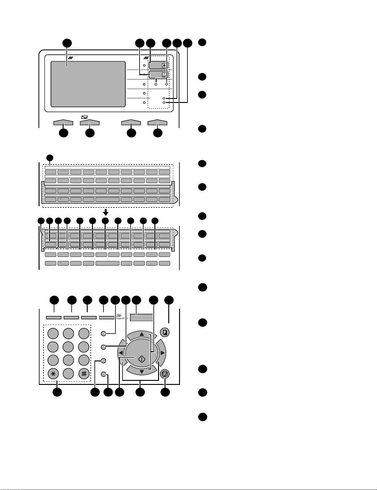
[3] Operation panel
1
DOCUMENT COMMUNICATION SYSTEM
CONTRAST RESOLUTIONe-mail ON LINE
7
11
01 02 03 04 05 06 07 08 09 10
Q/! W/" E/# R/$ T/% Y/& U/' I/( O/) P/=
11 12 13 14 15 16 17 18 19 20
SYMBOL
A/|S D F G/{ H/} J/[ K/] L/+
21 22 23 24 25 26 27 28 29 30
Caps Lock
Z/< X/> C V B N/* M/? @ .com
31 32 33 34 35 36 37 38 39
/^ // \ ;/:
SHIFT
11
40 41 42 43 44 45 46 47 48 49
50 51 52 53 54 55 56 57 58 59
SYMBOL
PAGECOUNTER
Caps Lock
GHI
PQRS
14 15 16 17 18 19 2012 13
Q/! W/" E/# R/$ T/% Y/& U/' I/( O/) P/=
A/|S D F G/{ H/} J/[ K/] L/+
CONFIDENTIAL
TIMER
Z/< X/> C V B N/* M/? @ .com
SHIFT
/^ // \ ;/:
COVER SHEET
22 2923 24 25 30282726
JOB STATUS
DUPLEX SCAN
ABC1DEF
PRIORITY
2 3
JKL
MNO
4
5
TUV
7
OPER
6
WXYZ
9
8
0
31 35 3632 3433
3 5 62
4
HALF TONE
STANDARD
SUPER FINE
ULTRA FINE
FINE
ALARM
TONER
Network
DATA
ON LINE
FAX2FAX1
98 10
Space
LIFE
MEM.STATUS
Space
BROADCAST
PERSONAL
BOOK
SPEED DIAL
ZA
REDIAL
GAB SEARCH
SPEAKER
_
REPORT
_
- ./, DEL
21
LINE
DOCUMENT
- ./, DEL
MENU
UP
START/
ENTER
DOWN
COPY
STOP
Display
1
This displays messages and prompts to help you operate
the machine. The backlight turns on whenever a key is
touched, and then automatically turns off after a preset time
if no further operations are performed. The display can be
tilted to the desired angle for easy viewing.
TONER indicator
2
This blinks when the toner cartridge nears empty, and lights
steadily when the toner cartridge needs replacement.
ALARM indicator
3
This blinks when one of the paper sources is empty, or the
drum cartridge is near or at the end of its life. This lights
steadily when all paper sources are empty, the print
compartment cover is open, or a paper jam has occurred.
A message will appear in the display to indicate the problem.
FAX1 / FAX2 lights
4
When the dual line option is installed, FAX 1 lights when
Line 1 is being used and FAX 2 lights when Line 2 is being
used. When the dual line option is not installed, only FAX 1
lights when the telephone line is being used (the FAX 2
light does not operate).
DATA light
5
This blinks when the machine is receiving a print job over
the network (only when the network printer option is
installed).
ON LINE light (printer option only)
6
When this light is on, the machine can receive data (print
jobs) over the network. The light is turned on or off with the
ON LINE key. (Only available when the network printer
option is installed).
CONTRAST key
7
Press this key to adjust the contrast before sending or
copying a document.
E-mail key
8
Press this key to send a scanned document to an e-mail
recipient. (Only available when the network scanner option
is installed).
RESOLUTION key
9
Press this key to adjust the resolution before sending or
copying a document. An indicator will light next to the
selected setting (HALFTONE, STANDARD, FINE, SUPER
FINE or ULTRA FINE).
ON LINE key (printer option only)
10
Press this key to select whether the machine is online or
off-line (the ON LINE light is on when the machine is
online). The machine must be online to receive print
jobs over the network. (Only available when the network
printer option is installed).
Rapid Dial Keys
11
Press one of these keys to dial a fax number automatically,
or specify an e-mail recipient if the network scanner option
is installed. Note that you must attach the Rapid Key labels.
When navigating through the display menu, a Rapid Key
can also be pressed in place of the numeric keys to enter
a two-digit number (for example, you can press Rapid Key
01 to enter the number "01").
SYMBOL key
12
When entering a name, press this key to enter the symbol
on a letter key (the character to the right of the slash).
Press the key again to turn off symbol entry mode.
PAGE COUNTER key
13
Press this key to include a slash and the total number of
pages after each page number on the pages of a
transmitted document.
CONFIDENTIAL key
14
Press this key to send or print out a confidential document.
FO-DC635U
1 – 4

FO-DC635U
d
TIMER key
15
Press this key to set a fax operation to be performed
automatically at a later time.
COVER SHEET key
16
Press this key to include a cover sheet when sending a fax.
LIFE key
17
Press this key, followed by , to check the total number of
pages printed by the fax machine. (Press to return to the
data and time display.
MEM. STATUS key
18
Press this key to check the status of fax transmission jobs,
copy jobs, and fax receptions. This key can also be used to
cancel a job.
19
REPORT key
Press this key before sending a fax (on a Scan to E-mail/FTP/
Desktop transmission when the network scanner option is
installed) to have a transaction report printed out after the
transmission is finished.
DOCUMENT key
20
Press this key to transmit a document directly from the feeder
without reading it into memory.
LINE key
21
When the dual line option has been installed, press this key
before dialing to select the line.
JOB STATUS key
22
Press this key to display the FAX-STATUS screen, which
shows information on the fax job that is currently in progress.
If the dual line option is installed, the fax status will appear
separately for each line. If the network printer option is
installed, the NETWORK PRINT STATUS screen showing
information on current printer activity will appear following
the FAX STATUS screen (note that "IDLE" will appear if a
print job has been executed but is not yet being printed).
To move through each of the screens and return to the date
and time display, press one or more times as needed.
JOB STATUS
START/
ENTER
STOP
29
UP and DOWN arrow keys
Volume setting: Press these keys to change the speaker
volume when the SPEAKER key has been pressed, or the
ringer volume at any other time.
MENU key settings: Press these keys after pressing the
MENU key to scroll through the MENU key settings.
30
COPY key
Press this key to make a copy of a document that is in the fee
31
Dial keypad (numeric keys)
Use these keys to dial and program fax numbers.
REDIAL key
32
Press this key to automatically redial the last number dialed.
SPEAKER key
33
Press this key when faxing a document by Normal Dialing to
listen to the line and verify the response of the receiving fax
machine.
START/ENTER key
34
Press this key to begin fax transmission when using Speed
Dialing, Direct Keypad Dialing, or Normal Dialing. This key is
also used to select settings in the MENU key menu and
complete entries when storing names and numbers.
Left and right arrow keys
35
Press these keys to search for an auto-dial number when
sending a document. If the network scanner option is installed
and your network has an LDAP server, the left arrow key
(GAB SEARCH) can be pressed to search for a destination on
the LDAP server. (Note: "GAB" stands for "Global Address
Book".)
36
STOP key
Press this key to cancel an operation before it is completed.
DUPLEX SCAN key
23
Press this key to transmit or copy a two-sided document.
PRIORITY key
24
Press this key when you need to transmit a document ahead
of other documents waiting in memory for transmission.
BROADCAST key
25
Press this key to send a document to a group of fax
machines, or to a group of e-mail recipients if the network
scanner option is installed.
26
PERSONAL BOOK
Press this key to use or store an auto-dial number in a
personal book. If the book has a passcode, enter the
passcode; otherwise, select the book with or and
START/
ENTER
press .
27
SPEED DIAL key
Press this key to dial a Speed Dial number.
MENU key
28
Press this key to select special functions and setting.
1 – 5

[4] Transmittable documents
1. Document Sizes
Normal size Width 5.8” - 10.1”(148 - 257 mm)
Length 5.0” - 14.3”(128 - 364 mm)
(Max.)
80g/m
966mm
2
(Max.)
(Min.)
364mm
128mm
148mm 257mm
[Normal size]
• With special sizes, only one sheet can be fed into the machine at a
time. Insert next page into feeder as current page is being scanned.
279mm
[Special size]
2. Paper Thickness & Weight
Product specifications
Indication Lower Limit Upper Limit
Weight indication
Thickness
indication
Document
size
Number of
ADF sheets
Paper quality
Japanese indication Size 4 x 6
Metric system
indication
American indication LB system indication
Metric system
indication
Inch system
indication
Document size
Range
Document size
Weight
Kind Paper of fine quality/bond paper/
45kg paper 70kg paper
2
52g/m
14 LB 20 LB
0.06mm 0.1mm
0.0024" 0.0035"
(148mm x 128mm) ~
W letter (279mm x 483mm)
A4 (210mm x 297mm)
Letter (216mm x 279mm)
B6 ~ Letter/A4 size 50sheets
B4 size/Legal 20sheets
W letter size 1sheet
90 kg (104g/m
135 kg (157g/m
Kent paper
2
) or more
2
) or less 1sheet
3. Document Types
• Normal paper
Documents handwritten in pencil (No. 2 lead or softer), fountain
pen, ball-point pen, or felt-tipped pen can be transmitted.
Documents of normal contrast duplicated by a copying machine
can also be transmitted.
• Diazo copy (blue print)
Diazo copy documents of a normal contrast may be transmitted.
• Carbon copy
A carbon copy may be transmitted if its contrast is normal.
FO-DC635U
4. Cautions on Transmitting Documents
• Documents written in yellow, greenish yellow, or light blue ink cannot be transmitted.
• Ink, glue, and correcting fluid on documents must be dry before the
documents can be transmitted.
• All clips, staples and pins must be removed from documents before
transmission.
• Patched (taped) documents should be copied first on a copier and
then the copies used for transmission.
• All documents should be fanned before insertion into the feeder to
prevent possible double feeds.
5. Automatic Document Feeder Capacity
Number of pages that can be placed into the feeder at anytime is as
follows:
Normal size: max. 50 sheets (14 lbs - 20 lbs)
Special size: single sheet only (manual feed)
NOTE: • If you need to send or copy more 50 pages, place the addi-
tional pages and carefully in the feeder just before the last
page is scanned. Do not try to force them in, as this may
cause double-feeding or jamming.
• If your document consists of several large or thick pages
which must be loaded one at a time, insert each page into the
feeder as the previous page is being scanned. Insert gently to
prevent double feeding.
6. Readable Width & Length
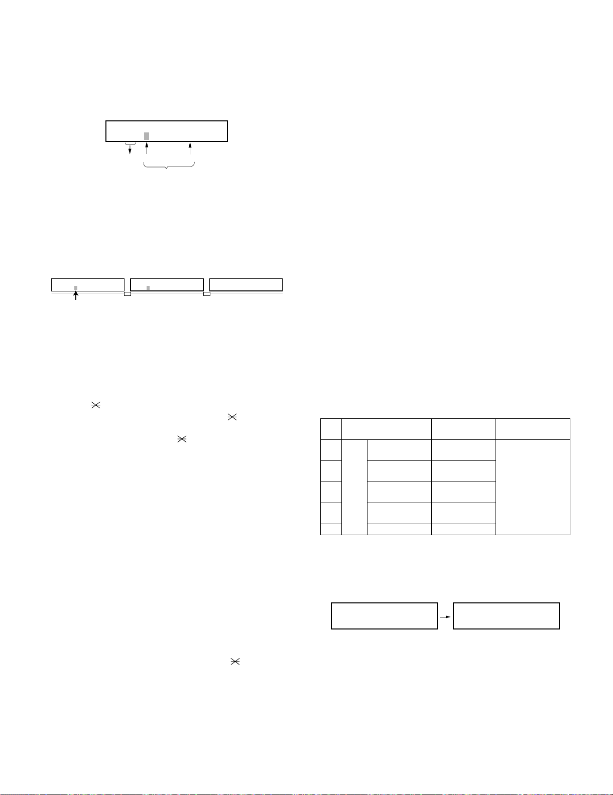
The readable width and length of a document are slightly smaller than
the actual document size.
Note that characters or graphics outside the effective document scanning range will not be read.
• Readable width
10” (257mm), max
Readable width
• Readable length
This is the length of the document sent minus 0.16” (4mm) from the
top and bottom edges.
0.16" (4mm)
Readable length
0.16" (4mm)
1 – 6

FO-DC635U
[5] Installation
1. Site selection
Take the following points into consideration when selecting a site for
this model.
ENVIRONMENT
• The machine must be installed on a level surface.
• Keep the machine away from air conditioners, heaters, direct sunlight, and dust.
• Provide easy access to the front, back, and sides of the machine.
In particular, keep the area in front of the machine clear, or the original document may jam as it comes out after scanning.
• The temperature should be between 50 - 86°F (10 - 30°C).
• The humidity should be between 20% and 85% (without condensation).
ELECTRICITY
AC 120V, 60Hz, grounded AC (3-prong) outlet.
Caution!
• Connection to a power source other than that specified will cause
damage to the equipment and is not covered under the warranty.
• If your area experiences a high incidence of lightning or power
surges, we recommend that you install a surge protector for the
power and telephone lines. Surge protectors can be purchased at
most telephone specialty stores.
TELEPHONE JACK
A standard telephone jack must be located near the machine. This is
the telephone jack commonly used in most homes and offices.
• Plugging the fax machine into a jack which is not an RJ11C jack
may result in damage to the machine or your telephone system. If
you do not know what kind of jack you have, or need to have one
installed, contact the telephone company.
If the machine is moved from a cold to a warm place...
If the machine is moved from a cold to a warm place, it is possible that
the reading glass may fog up, preventing proper scanning of documents for transmission. To remove the fog, turn on the power and wait
approximately 2 hours before using the machine.
2) Connecting the telephone line cord
Insert one end of the line cord into the jack on the back of the
machine marked TEL. LINE. Insert the other end into a standard
(RJ11C) single-line wall telephone jack.
Note: The fax machine is set for touch-tone dialing. If you are on a
pulse dial (rotary) line, you must set the fax machine for pulse dialing by changing Option Setting 22.
3) Attaching the ADF exit tray
Insert the protrusion on the right side of the machine into the hole in
the right side of the ADF exit tray , then bend the tray
slightly and insert so that the protrusion on the left side of the
machine goes into the hole on the left side of the ADF exit tray
. Pull out the tray extension .
2
2
1
3
1
3
2. Assembly and connections
1) Connecting the power cord
Connect the female end of the power cord to the fax machine as
shown. Insert the male end into a 120 V, 60 Hz, grounded (3-prong)
AC outlet.
Important!: The fax machine requires its own dedicated power outlet. The power outlet must not be shared with any other devices. In
particular, do not use an extension cord to connect multiple devices
to the outlet.
Note: If your area experiences a high incidence of lightning or
power surges, we recommend that you install surge protectors for
the power and telephone lines. Surge protectors can be purchased
at most telephone specialty stores.
Press the power
switch to turn on
the power.
4) Attaching the received document tray
Slide the received document tray into the machine as shown. When
it stops, lift the end slightly and push in so that the tray locks into
place.
Important!: The received document tray must be attached for the
fax machine to operate properly.
1 – 7
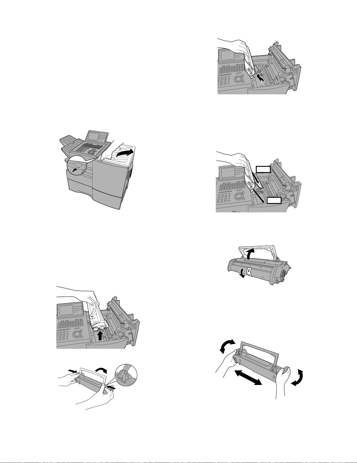
3. Installing the print cartridges (Toner cartridge:
FO-50ND)(Drum cartridge: FO-47DR)
Follow the steps below to install or replace the toner and drum cartridges.
• The initial starter toner cartridge included with the fax machine can
print approximately 3000 letter-size pages (4% coverage of each
page; continuous printing).
• The replacement toner cartridge (FO-50ND) can print approximately 6000 letter-size pages.
• The drum cartridge (FO-47DR) can print approximately 20,000 letter-size pages.
1) Press the cover release to open the print compartment cover.
• Caution! The fusing unit inside the print compartment becomes
very hot during operation. Be careful not to touch the inside of the
compartment.
FO-DC635U
3) If you are replacing the drum cartridge, remove the old cartridge
and dispose of it according to local regulations.
4) Remove the new drum cartridge from its packaging. Insert the drum
cartridge into the print compartment.
• Caution! Excessive exposure to light will damage the drum car-
tridge. Install the cartridge promptly after removing it from its
packaging.
• Make sure the drum cartridge is inserted in as far as it will go.
BLUE
2) If you are replacing the toner cartridge, remove the old cartridge
and dispose of it according to local regulations.
Go directly to STEP 5 if you are only replacing the toner cartridge
and not the drum cartridge.
To make the cartridge more compact for disposal, press the buttons
on the ends of the handle and fold the handle down.
• If you are replacing the drum cartridge but not the toner car-
tridge, remove the toner cartridge and place it on a sheet of
paper.
GREEN
5) If you are installing a new toner cartridge, remove the new toner
cartridge from its packaging. Remove the tape from the cartridge
and then open the cartridge handle so that it stands straight up.
6) Shake as indicated by the arrows to distribute the toner evenly
within the cartridge.
• If the toner is still lumpy after shaking, the gears in the cartridge
may make a noticeable sound when the print compartment
cover is closed after installing the cartridge. This is normal and
does not indicate a problem.
1 – 8

FO-DC635U
Red line
7) Hold the toner cartridge by the handle and insert it into the print
compartment.
• Make sure the toner cartridge clicks into place.
• The handle can be left standing up.
11)When to replace the drum cartridge
When the drum cartridge nears the end of its life, the ALARM indicator on the operation panel will blink and REPLACE DRUM CARTRIDGE will appear in the display. (this message first appears
when approximately 1000 pages before the drum needs replacement). Use the following replacement drum cartridge.
Sharp FO-47DR drum cartridge
BLUE
GREEN
8) Close the print compartment cover.
9) Reset the drum counter by pressing (flip up the Rapid Key
LIFE
V
overlay), or until DRUM COUNTER CLEAR is selected
in the display, and then .
START/
ENTER
• Note: The toner counter automatically resets each time you
replace the toner cartridge. There is normally no need to reset
the toner counter manually. Should you find it necessary to
manually reset the toner counter, press (flip up the
LIFE
V
Rapid Key overlay), or until TONER COUNTER
CLEAR is selected, and then .
START/
ENTER
4. Loading printing paper
You can load up to 250 sheets of letter or legal paper (max. 20 lbs.) in
the paper tray. Depending on the model, a paper cassette is also
included as a standard fearure or available as an option. Up to 500
sheets of letter or legal paper can be loaded in the paper cassette.
• One paper cassette is inclued as a standard feature. A second
paper cassette is available as an option. To have a second cassette
installed, consult your dealer.
Important: Do not use the back side of paper that has already
been printed on.
Note: If you need to add paper to the tray or cassette while paper
still remains, remove the remaining paper and combine it into a single stack with the new paper.
Loading paper in the paper tray
1) Remove the received document tray.
2) Insert a stack of paper into the tray, print side up.
• Important! The stack of paper must not be higher than the red
line on the paper tray.
Note: The print compartment cover may become noticeably
warm if a large number of pages are successively printed. This
is normal and does not indicate a problem in the machine.
10)When to replace the toner cartridge
When the toner cartridge nears empty (about 100 pages can still be
printed), the toner cartridge indicator on the operation panel will
blink. When the toner cartridge is empty, the toner cartridge indicator will light steadily and REPLACE TONER CARTRIDGE will
appear in the display. Printing will no longer be possible. Use the
following replacement toner cartridge.
Sharp FO-50ND toner cartridge
Hint: When the toner cartridge nears empty, try taking it out of the
machine and shaking it. This may increase the number of pages
that can be printed before the toner runs out.
3) Squeeze the paper guide and move it to match the length of the
paper you are loading.
Attach a letter or
legal label here to
indicate the paper size.
1 – 9
4) Replace the received document tray.
• The received document tray must be attached for the machine
to operate properly.
FO-DC635U
4) Place a stack of paper in the cassette, print side up.
• Make sure the stack of paper is not higher than the two tabs on
the paper guide and the two metal tabs. If it is, remove some of
the paper.
• If you find it difficult to load the paper, remove the cassette from
the machine. (Pull the cassette out as far as it will go, grasp the
left side of the cassette with your left hand, and then lift it up and
out with both hands.)
5. Loading paper in the paper cassette
Note: To use A4 paper in the paper cassette, you must have a service
technician adjust the cassette.
1) Grasp the hand-hold on the cassette and pull the cassette out until
it stops.
2) Push the pressure plate down until it locks into position.
5) Push the cassette back into the machine, making sure it clicks into
place.
6. Clearing paper jams
Clearing a jammed document
If the original document doesn’t feed properly during transmission or
copying, or REMOVE ORIGINAL(S) appears in the display, fist try
START/
pressing . If the document doesn’t feed out, open the opera-
tion panel and remove it.
Important: Do not try to remove a document without opening the operation panel. This may damage the feeder mechanism.
1) Open the operation panel.
ENTER
• Squeeze the release marked PANEL RELEASE and pull up.
3) Squeeze the paper guide and pull up to move it to the appropriate
holes for the length of the paper. Push the guide down into the
holes.
1
2
2) Remove the document.
1 – 10
FO-DC635U
3) Close the operation panel, making sure it clicks into place.
4) Remove the jammed paper.
• Make sure no torn pieces of paper remain in the print compartment and rollers.
OR
7. Clearing a jammed printing paper
If the printing paper jams, PAPER JAM will appear in the display. Follow the steps below to clear the jam.
1) Press the green release and open the print compartment cover.
• Caution! The fusing unit inside the print compartment becomes
very hot during operation. Be careful not to touch the inside of
the compartment.
2) Remove the toner cartridge and place it on a sheet of paper.
5) Replace the drum cartridge.
• Make sure the drum cartridge is inserted in as far as it will go.
BLUE
GREEN
6) Replace the toner cartridge and then close the print compartment
cover.
BLUE
GREEN
3) Remove the drum cartridge.
7) If you have a paper cassette and the display still indicates that
paper is jammed, pull out the cassette and remove the jammed
paper.
8) Replace the paper cassette.
1 – 11
8. Replacing the Verification Stamp (FO-45VS)
If you are using the Verification Stamp function, you will need to
replace the ink cartridge in the stamp unit when it runs out of ink (when
the stamped mark on original documents becomes faint). A new ink
cartridge can be obtained from your dealer.
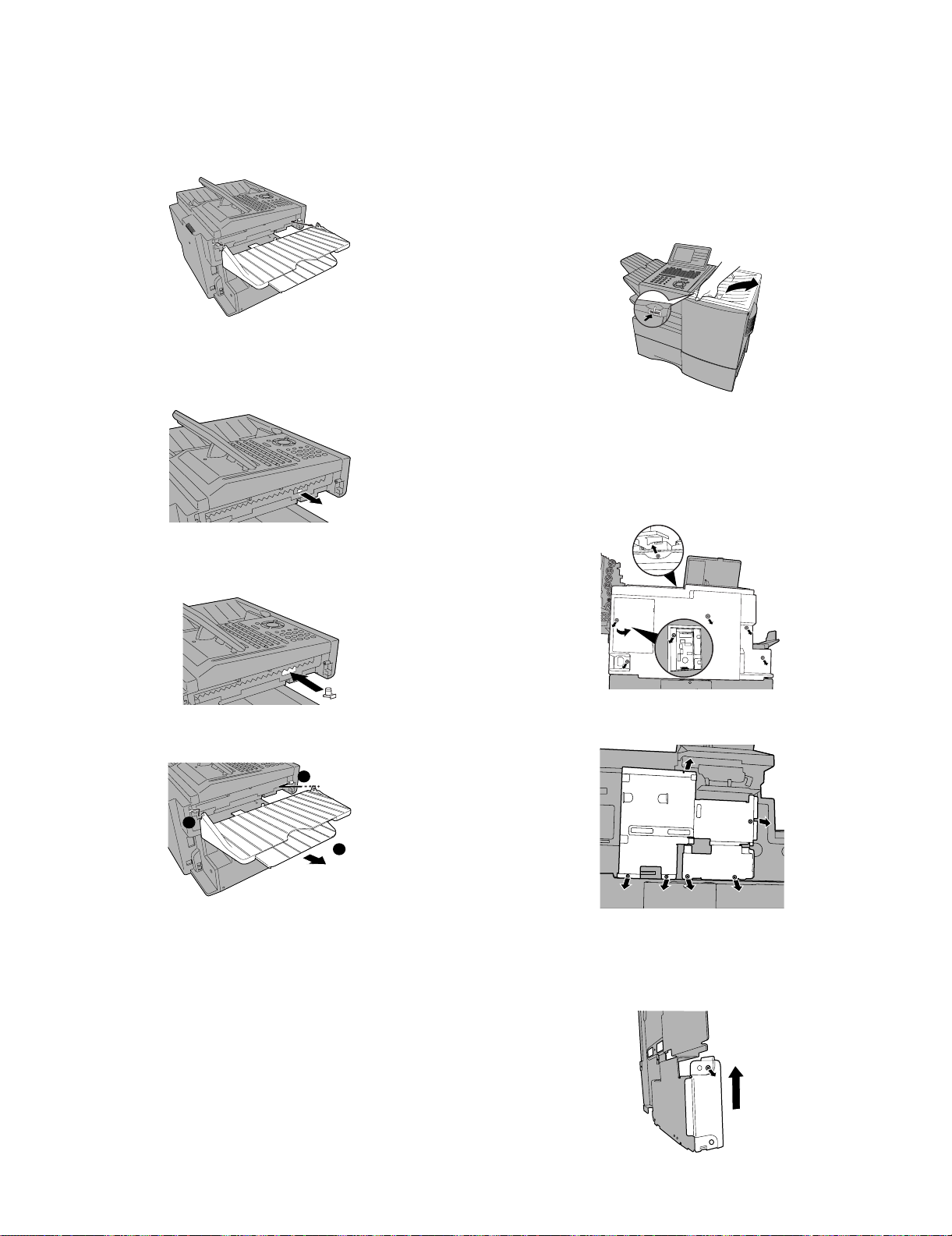
1) Remove the ADF exit tray.
2) Press down on the protruding tab of the green ink cartridge and pull
the cartridge out with your fingers.
FO-DC635U
9. Installing the Dual Line Kit (FO-60DL)
Note: The FO-60DL Dual Line Kit cannot be installed if the FO-NP1
Network Printer Kit is installed.
Important! The following procedure is to be performed only by a qualified service technician. Be sure to turn off the power, unplug the
power cord, and unplug the telephone line before proceeding. In addition, touch a grounded piece of metal to discharge any static electricity
that may be on your body. Make sure that an extension phone is not
connected to the machine.
1) Press the cover release to open the print compartment cover.
2) Remove 6 screws from the rear cover.
(Remember which screw secures the small cover on the left side of
the rear cover, as it must be replaced in the same position).
Remove the small cover, and then remove the screw underneath.
Remove the rear cover.
3) Insert the new ink cartridge into the machine (make sure that the
tab is facing out).
4) Replace the ADF exit tray.
1
2
3
3) Remove 6 screws and then remove the metal plate.
4) Remove the screw that holds the small side plate to metal plate
that was removed Step 3. Slide the small side plate up and remove
it from the metal plate. (Note: The small side plate is not no longer
needed, however, the screw is used again in “b” of Step 5.)
1 – 12
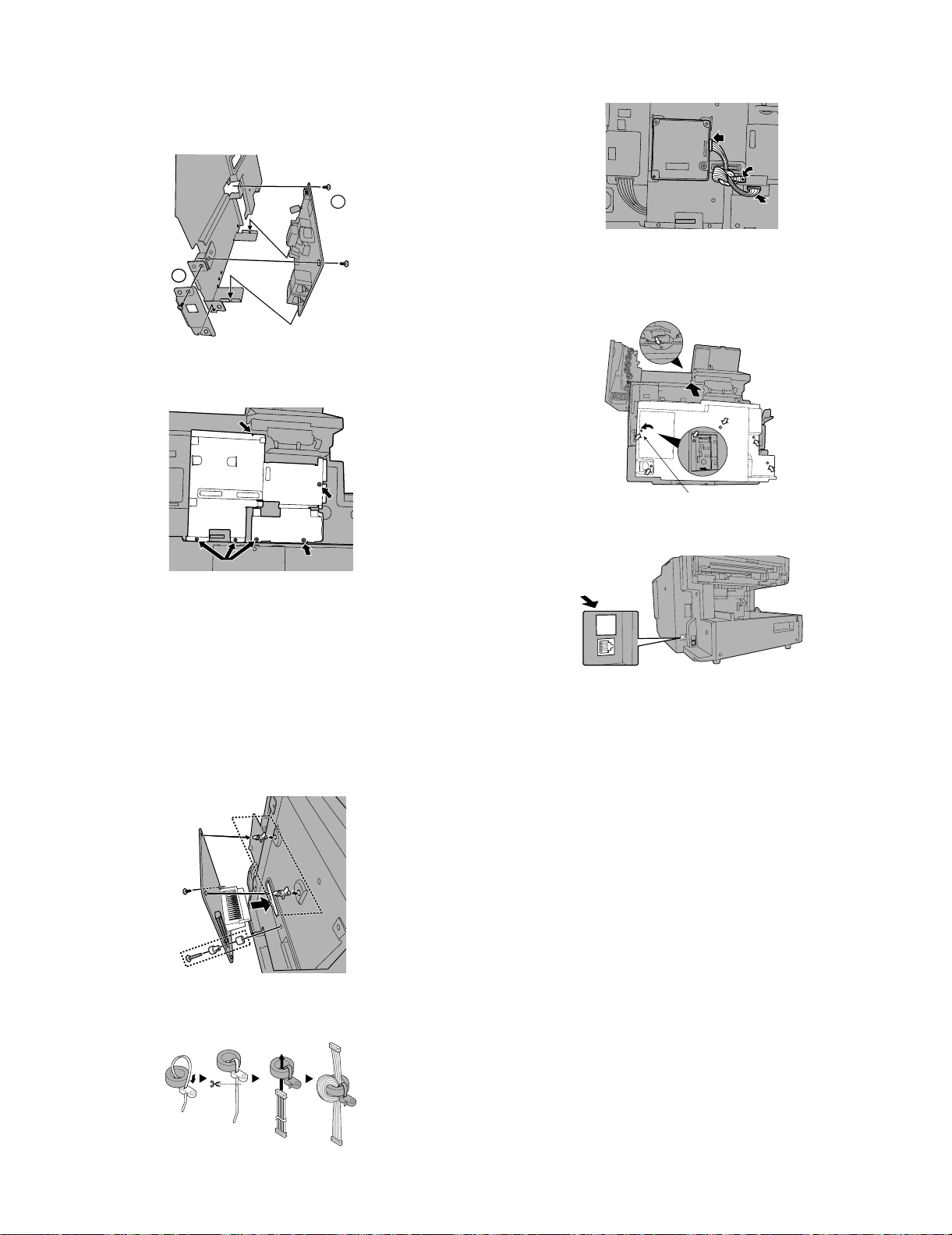
FO-DC635U
For plastic
5) a: Attach the LIU board to the metal plate, positioning the modular
jacks as shown. The bottom edge of the board should fit into the
slots indicated by the arrows. Secure the LIU board with two of the
6 mm screws.
b: Attach the provided metal side plate.
a
b
6) Replace the metal plate and secure with screws in the order
shown.
1
9) Connect the cable to the LIU board and the dual line control board.
Secure the core band with the 10 mm screw.
10)Replace the rear cover.
(Be sure to replace the screw that secures the small cover in the
same position, as it is for plastic.)
3
4
7) Attach the dual line control board.
a: Insert the bushing into the hole in the dual line control board from
the outer side and secure it with the collar on the inner side.
b: Insert the winged end of the pin spacers into the metal plate, with
wings extended out vertically.
c: Attach the board so that the connector inserts into the connector
in the metal plate. Make sure that the pin spacers go into the holes
in the board. Secure the board with the 18 mm screw (which goes
into the bushing) and the remaining 6 mm screw. Tighten the
screws in the order shown.
b
c
2
a
1
2
11)Affix the “”LINE 2” label above the new jack.
LINE 2
8) Fasten the band to the core as shown and cut off the excess end.
Insert the cable through the core and wind it around the core twice.
1 – 13
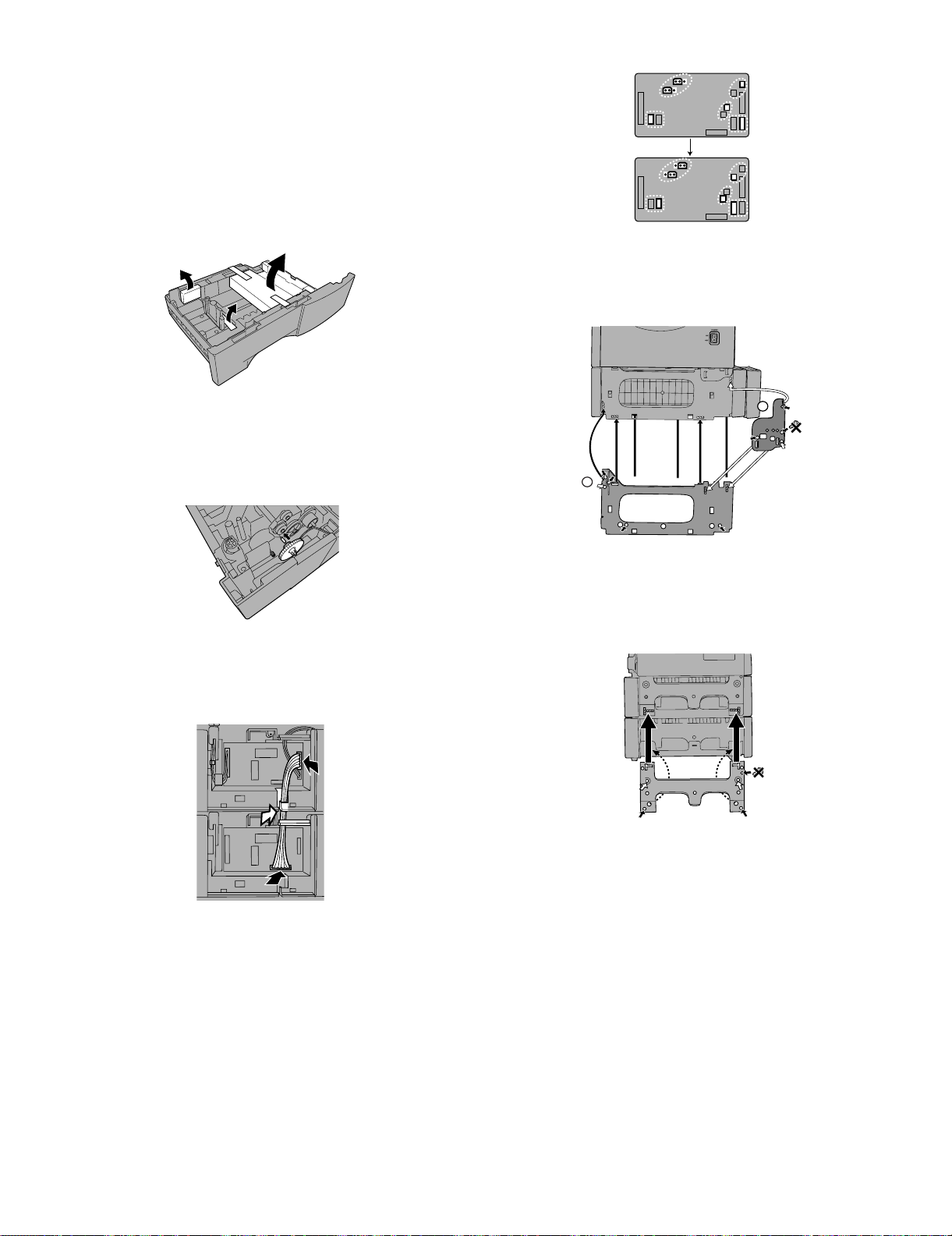
10. Installing the paper cassette option FO-CS2
(2nd)
Important! Be sure to turn off the power and unplug the power cord
before proceeding.
1) Remove the packing material and tape from the second paper cassette.
2) Remove the covers from the sides of the first cassette (the cassette
already installed on the machine), using a flat-head screwdriver to
pry each of the catches at the bottom of the covers free (2 on the
right cover, 3 on the left cover).
FO-DC635U
6) Attach the large support plate and then the small support plate to
the right side of the cassettes. Use 6 mm screws for the holes
marked with “A”, and 10 mm screws for the holes marked with “P”.
Secure the screws in the order indicated by the numbers.
3) Insert the green gear into the second cassette as shown. The side
of the gear that has the small secondary gear should face the
inside of the cassette, and should fit onto the metal shaft. Push the
gear in until the tab on the outer side goes into the slot on the metal
shaft. (Note: The gear is only used in the second cassette.)
4) Place the machine on top of the second cassette, and remove the
small cover from the rear of the first cassette. Connect the 10-pin
cable as shown, and insert it behind the guide indicated by the
white arrow.
2
A4
A4
P4
A3
1
A3
P3
A2
A1
7) Attach the support plate to the left side of the cassette. Use 6 mm
screws for holes marked with “A”, and 10 mm screws for holes
marked with “P”, securing the screws in the order indicated by the
numbers. (Note that the top hole on the right does not require a
screw.)
A4
P6
A2
A3
P5
A1
8) Attach the side covers to the first and second cassettes (refer to
steps 9 and 11 on the previous pages).
5) Change the positions of the connectors on the circuit board of the
second cassette as shown (do not change the connectors on the
first cassette). Replace the small cover on the rear of the first cassette, and attach the provided small cover on the rear of the second
cassette. (For the reconnection, see page 1-15.)
1 – 14

FO-DC635U
11. Caution when installing paper cassette option FO-CS2(2nd) to FO-DC635
When installing the option FO-CS2 to FO-DC635U as a 2nd paper cassette, the short pins and cables on the paper cassette PWB must be reconnected.
FO-DC635
+
FO-CS2
CAUTION
Connect 1 pin and 2 pin
-- -:@:H:9:N
1st Paper Cassette
2nd Paper Cassette
From the Motor
Connecting position of each cable when
installing Paper Cassette Option FO-CS2(2nd)
to FO-DC635.
1st paper cassette (CN6)/2nd paper cassette (CN7) cable
From the Solenoid
From the Paper
size sensor
From the
Cassette sensor
1 – 15

12. Quick reference guide
START/
ENTER
START/
ENTER
START/
ENTER
STOP
12.1. SENDING FAXES
Place your document (up to 50 letter-size pages) face down in the document feeder.
FO-DC635U
To store a Speed Dial number, press and enter a number
from 1 to 200 (press if you entered a 3-digits).
START/
ENTER
(If clearing a number, select it as explained above and then press
STOP
and .)
6) If the network scanner option is installed, SELECT DESTINATION
TYPE will appear. Make sure that FAX is selected and press
SPEED DIAL
(Note: For Normal Dialing and Direct Keypad Dialing, you can also
load the document after dialing the number.)
RESOLUTION
Press or if needed.
CONTRAST
12.1.1 Normal Dialing
1) Lift extension phone or press .
2) Dial the fax number (if using an extension phone, dial on the extension phone keypad).
3) Wait for the reception tone (if a person answers, ask them to press
their Start key).
START/
4) Press .
ENTER
SPEAKER
12.1.2 Rapid Key Dialing
1) Press the desired Rapid Key.
12.1.3 Speed Dialing
1) Press and enter the desired Speed Dial number (press
SPEED DIAL
START/
if you entered a 3-digits number).
ENTER
.
7) Enter the full fax number and press .
8) Enter a name by pressing the letter keys and press .
START/
ENTER
START/
ENTER
9) Select YES if this is a Chain Dial number or NO if not, and press
.
10)If the dual-line option is installed, select LINE-1, LINE-2, or AUTO
and press .
START/
ENTER
11)Press repeatedly to exit.
START/
2) Press .
ENTER
12.1.4 Direct Keypad Dialing
1) Dial the fax number.
START/
2) Press .
ENTER
12.2. STORING AUTO DIAL NUMBERS
1) Press and then or until ENTRY MODE is
selected in the display.
2) Press . Make sure that DESTINATION SETTING is
selected.
3) Press . Make sure that SET is selected. (To clear a num-
ber, select CLEAR.)
4) Press .
5) To store a Rapid Key number, press the desired Rapid Key.
MENU
START/
ENTER
START/
ENTER
START/
ENTER
1 – 16

FO-DC635U
FO-DC635U
CHAPTER 2. ADJUSTMENTS
[1] Adjustments
General
Since the following adjustments and settings are provided for this
model, make adjustments and/or setup as necessary.
1. Adjustments
Adjustments of output voltage (FACTORY ONLY)
1. Install the power supply unit in the machine.
2. Set the recording paper and document.
3. When the document is loaded, power is supplied to the output
lines. Confirm that outputs are within the limits below.
Output voltage settings
POWER
SUPPLY
PWB
1
1
CN5
HIGH VOLTAGE
PWB
12
CN1
VR51
CN1
8
1
10
Service Manual
CONTROL PWB
CNPW1
112
8
10
CN7
CN4
1
1
CNPRT1
130
130
CN1
PRINTER PWB
Output Voltage limits Note
+5V MAIN 4.947V~5.25V CN5 7pin ↔ 8pin
+24V SUB 23.04V~24.96V CN5 1pin ↔ 2pin
Connector CN4
No.
Pin No. CN1
111+5V
210CHLREM
3TVR
4TMONV
5TMONI
6BVR
7VREM
8 C MON
9MG
10 2 +24V
9
8
7
6
5
4
3
Connector CN5
No.
Pin No. CNPW1
1 +24V SUB
2MG
3MG
4MG
5 +24V MAIN
6 +24V MAIN
7 +5V MAIN
8DG
9DG
10 DG
11 +5V MAIN
12 +5V MAIN
Connector CN1
No.
Pin No. CN7
1 +24V MAIN
2MG
3DG
4DG
5 +5V MAIN
6 +5V MAIN
7 HEATER ON
8 H-RELAY OFF
[DO NOT TOUCH!]
Fig. 1
2 – 1
2. IC protectors replacement
ICPs (IC Protectors) are installed to protect the CIS unit, panel PWB
unit, TX motor drive circuit and verification stamp drive circuit. ICPs
protect various ICs and electronic circuits from an overcurrent condition.
The location of ICPs are shown below:
FO-DC635U
CONTROL PWB
(TOP SIDE)
1
CNSP1
2
1
CNSEN1
8
F1
CNCIS1
10 1
F2
27
F5 F100
228
CNPN1
1
CNSTP1
1214
CNTXM1
1) F1 (ICP-S0.5) F2 (ICP-S1.0) is installed in order to protect IC’s
from an overcurrent generated in the CIS unit. If F1 or F2 are open,
replace it with a new one.
2) F5 (ICP-S1.0) is installed in order to protect IC’s from an overcurrent generated in the panel PWB unit. If F5 is open, replace it with a
new one.
3) F100 (ICP-S1.0) is installed in order to protect IC’s from an overcurrent generated in the verification stamp drive circuit. If F100 is
open, replace it with a new one.
4) F101 (ICP-S1.8) is installed in order to protect IC’s from an overcurrent generated in the TX motor drive circuit. If F101 is open,
replace it with a new one.
F102
12 1
CNPW1
CNLIU1
F101
IC3
F1/F2/F5:Top side
F100/F101/F102:Bottom side
Fig.2
5) F102 (ICP-S0.7) is installed in order to protect IC’s from an overcurrent generated in the LCD drive circuit. If F102 is open, replace
it with a new one.
In addition to the replacement of F1, F2, F5, F100, F101 andF102
the factor causing F1, F2, F5, F100, F101 and F102 to open must
also be repaired. If not, F1, F2, F5, F100, F101 and F102 will open
again.
Replacement parts
ICP-S0.5 (Sharp code: VHViCPS05//-1)
ICP-S0.7 (Sharp code: VHViCPS07//-1)
CP-S1.0 (Sharp code: VHViCPS10//-1)
CP-S1.8 (Sharp code: VHViCPS18//-1)
3. Settings
3.1. Dial mode selector
OPTION SETTING: DIAL MODE (Soft Switch No. SW2 DATA No.1)
Use this to set the fax machine to the type of telephone line you are
on.
• The factory setting is "TONE".
(step 1) Select "OPTIONAL SETTING".
KEY:
DISPLAY:
(step 2) Select "DIAL MODE".
(step 2) Select "DIAL MODE".
KEY:
KEY:
DISPLAY:
DISPLAY:
(step 3) Select, using "1" or "2".
KEY:
DISPLAY: TONE SELECTED
KEY:
DISPLAY:
(step 4) End, using the "STOP" key.
KEY:
MENU 4
OPTIONAL SETTING MODE
2
2
2
2
22: DIAL MODE
22: DIAL MODE
1=TONE
2=PULSE
1
2
PULSE SELECTED
STOP
<With optional line unit>
22: DIAL MODE
1=LINE-1
2=LINE-2
Select line using "1" or "2"
KEY:
1
DISPLAY:
DIAL MODE(LINE-1)
1=TONE
KEY:
DISPLAY:
2=PULSE
2
DIAL MODE(LINE-2)
1=TONE
2=PULSE
2 – 2
FO-DC635U
Press
, and
the
following
display will appear.
MENU
9 8
6
PCU ROM VER.:
(Diag¥specifications)
MENU
9 8 6
START
01
AREA PRINT MODE 1
START
02
CHECK PATTERN 1
START
03
CHECK PATTERN 2
START04
CHECK PATTERN 3
START05
CHECK PATTERN 4
START06
PAPER FEED AGING 1
START07
PAPER FEED AGING 2
START
START
08
BIAS ADJUST MODE2
START
09
LIFE SET MODE
START
START
Then press the
key. Select the desired item with the
key and the key or select with the rapid key.
Enter the mode with the key.
START10
LIFE ALL CLEAR
START11
LIFE ENTRY MODE
PCU ROM Ver.:
START12
LIFE CLEAR MODE
[2] Diagnostics and service soft switches
1. Operating procedure
Two kinds of diagnoses are supported.
1.1. Fax diagnosis
This diagnosis is concerned with the main body of fax which is used
for production and service support.
Entering the diagnostic mode
1.2. Print diagnosis
This diagnosis is concerned with the print which is used for production
and service support.
Entering the diagnostic mode
Press
MENU
9 8
display will appear.
FAX
:TF23
NIC:x.xxx
PRN:xxxx
PRN
MEMORY
GAA:ESx GAB:ESx
Then press the
SIZE=16(MB)
START
key. Select the desired item with the
and the key or select with the rapid key.
Enter the mode with the
(Diag
¥
specifications)
MENU
9 8 7
B PRINT AREA
C ROM & RAM CHECK
D AUTO FEEDER MODE
E AGING MODE
F PANEL CHECK MODE
G OPTICAL ADJUST MODE
H PRODUCT CHECK
I
J
K
L
M
N
O CONF. PASSCODE
P
Q
R
S
T
U
V
W
X
Y
Z
@
*: FONT LIST PRINT MODE can be used only when the
network function is effective.
START
STARTA SOFT SWITCH MODE
START
START
START
START
START
START
START
START
START
START
START
START
START
START
START
START
START
START
START
START
START
START
START
START
START
START
7
,and
1stLine
nd
2
Line
rd
3
Line F/W version
th
4
Line NIC board version
th
5
Line PCL board version
th
Line
6
th
7
Line Memory size
th
8
Line GATE arrayA/B version
th
9
Line
key.
TF23
START
SIGNAL SEND MODE
COMM. CHECK MODE
MEMORY CLEAR MODE
FLASH MEMORY CHECK
ALL FAX/TEL. ENTRY MODE
DEPT. PASSCODE
SIGNAL SEND MODE 2
MEMORY SET MODE
STAMP AGING MODE
DIAL TEST MODE
COPY DIAG MODE
LCD CHECK MODE
PERSONAL BOOK LIST
FONT LIST PRINT MODE(*)
NO FUNCTION
NO FUNCTION
ADMIN PASSWORD
PRINT HOLD CODE
the
following
key
Memory clear when power is turned on
Pressing the STOP keys, turn on the main power, and the following
message will be displayed.
MEMORY CLEAR ?
1 = ALL , 2 = IMAGE , 3 = NO
1 = All the data will be deleted including initially registered data.
2 = Delete the image file to be used in transmission. This will delete all
the data related to communication such as reserved transmission or
intercepting. However, the data initially registered will not be deleted.
3 = Memory will not be cleared and the machine enters stand-by
mode.
2 – 3
2. Diagnostic items description
ROM SRM DRM1 DRM2
••••
ROM SRM DRM1 DRM2
PPP E
Display during check Display after check
P=PASS E=ERROR
2.1. Fax diagnosis
2.1.1 (A) Soft switch mode
In this mode, the soft switch are set and the soft switch list is printed.
Soft switch mode screen
SOFT SWITCH MODE
SW01=00000000
1234567 :DATA No.
Switch
No.
1. Switch number selection
• Press START key for setting of the next soft switch. If the soft
switch number is the final, pressing START key will exit the soft
switch mode.
• Enter two digits of a soft switch number to set the switch number. If a switch number of nonexistent soft switch is entered, key
error buzzer sounds to reject the input.
SOFT SWITCH MODE
SW01=00000000
Cursor
1 6
2. Data number selection
The cursor position shows the data to be set.
Pressing # key or → key moves the cursor to the right. If, however,
the cursor is on data number 8, pressing # key or → key shifts the
cursor to data number 1 of the next switch number. If the switch
number is the final, pressing # key or → key will exit the soft switch
mode.
Pressing key or ← key moves the cursor to the left. If, how-
ever, the cursor is on data number 1, pressing key or ← key
shifts the cursor to data number 1 of the former switch number. If
the switch number is 1, pressing key or ← key will not move
the cursor and the error buzzer will sound.
3. Data setting method
Press the MENU key, and the data at the position of the cursor will
be reversed to 0 when it is 1, or to 1 when it is 0. (If the soft switch
can be changed at the bit (Refer to 6.), the error buzzer will sound
with the process not received.)
4. Outputting method of soft switch list
In the soft switch mode, press the REPORT key, and the soft switch
list will be output.
If the recording paper runs out or is clogged, the key error buzzer
will sound with the process not received.
5. Storage of data
In the following case, the data of the soft switches set will be
stored.
• It is shifted to set the next soft switch by pressing the START
switch.
• It is shifted to set the next soft switch with the [#] key.
• It is shifted to set the last soft switch with the [ ] key.
• It is shifted to set another soft switch by inputting two digits as
the switch number. (When 2 digits are completely input.)
• Output of the soft switch list is started.
6. Inhibition of data change
(This is also applicable for the optional setting.)
In the following case, it is inhibited to change the data with the key
error buzzer.
Data
ENTER LAST DIGIT
SW1
8
SOFT SWITCH MODE
SW16=00010110
FO-DC635U
• Switching ON/OFF of ECM during the use of image memory.
• OFF to ON of telephone billing function which is using the image
memory is used (Note: In the existing set, the telephone billing
code function is specified from OFF to ON when the timer system communication (including the batch communication) is set.)
Here, the memory is usable when the telephone billing code
function is on. It can be set from ON to OFF while the memory is
used. However, if setting is practically changed even once, it
can not be returned from OFF to ON.
• OFF to ON of department control function during use of image
memory.
(Note: In the existing set, the department control function is set
from OFF to ON when the timer communication (including the
batch sending) or the memory hold is set.)
• ON to OFF of continuous serial polling function when the continuous serial polling is started.
(Note: In the existing set, "ON to OFF of the continuous serial
polling function when the continuous serial polling is registered"
has been applied, but the conditions are now moderated. However, registration is impossible to the program of the new continuous serial polling when the continuous serial polling function is
OFF.)
• In addition, change of all soft switches during communication.
2.1.2 (B) Print area
According to the size of the specified sheet, the effective printing area
is printed.
2.1.3 (C) ROM & RAM check
This is an item to check if the loaded memory device acts normally.
• The memory devices shown in the following table are checked.
• In case that an error occurs in the device check, the alarm buzzer
shown in the table sounds.
Check device and alarm buzzer
No. Device checked Number of
1
ROM (PROGRAM FLASH)
2 SRAM <Short sounds>
3 D-RAM1 (*1) <Short sounds>
Main
4 D-RAM2 (*2) <Short sounds>
5— —
*1: Work memory (SDRAM 8MB)
*2: Page memory (SDRAM 16MB)
(Example of display) In case that DRAM2 is erroneous.
• After the check is complete, the result is outputted.
• In case that an NIC and a PCL board are mounted, the version
information of the board is also printed on the result.
2 – 4
buzzer sound
<Short sound>
1 time
2 times
3 times
4 times
<Short sound>:
0.5 sec.ON / 0.5
sec.OFF
<Long sounds>:
1.0 sec.ON / 0.5
sec.OFF
Remarks

FO-DC635U
2.1.4 (D) Auto feeder mode
By executing the document insertion and discharge, the automatic
feeding function can be checked. And the document sensor can be
checked as well.
1. Set the document
Before pressing the “START” key, only the document sensor check
is carried out. And as the document sensor is ON, the document
size (A4/B4) and the sensor information (A4/B4/ORG) are displayed.
AUTO FEEDER MODE
()
After setup of the document
AUTO FEEDER MODE
B4 (A4 B4 ORG)
Only the sensor which is
activated (fallen down) is displayed.)
The paper sheet size (A4/B4) is
displayed.
2. The automatic feeding starts by pressing the “START” key. This
mode ends when the document ends, and the result is printed.
2.1.5 (E) Aging mode
This is a mode to execute the copying action and the check pattern
printing action once every 60 minutes and continue the action until 10
sheets are outputted in total.
1. The printing action on the 1st sheet starts by pressing down the
“START” key and entering the mode. When document is set at the
time of the mode start-up the copy action is carried out, and when
the document is not set the “check pattern 1” of the print dialog is
printed.
2. The number of printouts is displayed after printing.
2.1.6 (F) Panel check mode
This is to check that each key acts normally and this is displayed on
the LCD according to the key input. And during execution, the document reading lamp is ON. After inspection start, the LEDs light on
sequentially. At the mode end with the “STOP” key, all of them go OFF.
As to the test result, it is printed out after the mode end.
When the “NUMERIC” key is pressed during the panel check execution, sending of the DTMF signal corresponding to the key starts, and
when another key is pressed sending of the DTMF signal stops.
(Softswitch change is required. SW80 No.6: 0 →1)
• After inputting all the keys, input the “STOP” key at last, and then
the result is displayed.
a) In case that all the keys are pressed.
PANEL CHECK MODE
ALL KEY OK !!
• Until the STOP key is pressed, all black 4-split sequential display is
performed.
• After the mode end, the test result is printed.
b) In case that there is a key that is not pressed.
2.1.7 (G) Optical adjust mode
The optical system is adjusted.
• By pressing down the “START” key, the document reading lamp
“100%: ON” is turned ON.
2.1.8 (H) Product check
This is a dialog used in the production process and a mode to execute
a specific mode in the series of the flow. After the mode end, the rest
result as to the checked items is printed.
• After moving to the mode, the following actions are sequentially
executed.
1. Memory clear (Same as Diagnosis K)
2. Panel check (Same as Diagnosis F)
3. ROM & RAM test check (Same as the Diagnosis C)
4. Test result print
Memory clear printing
Panel check result printing
ROM & RAM test result printing
5. Print area (The specification of each item is the same as the specification of the simple mode.)
2.1.9 (I) Signal send mode
It can be used to check the modem. When the START key is pressed,
silence signal (make loop) will be executed. The following signals are
sent by pressing the START key thereafter.
[1] No signals (mark loop) [9] 9600bps (V. 29)
[2] 4800bps (V27ter) [10] 7200bps (V. 29)
[3] 14400bps (V. 33) [11] 4800bps (V.29ter)
[4] 12000bps (V. 33) [12] 2400bps (V.29ter)
[5] 14400bps (V. 17) [13] 300bps (FLAG)
[6] 12000bps (V. 17) [14] 2100Hz (CED)
[7] 9600bps (V. 17) [15] 1100Hz (CNG)
[8] 7200bps (V. 17)
2.1.10 (J) Comm. check mode
1. Turn on the Line Monitor. (SW7 No.7, SW29 No.7)
2. Turn off the Cover Sheet Function. (SW2 No.6, SW24 No.6)
3. Set Line Equivalence at 0 km. (SW8 No.1/No.2, SW30 No.1/No.2)
4. Set the copy cut off mode (SW75 No.2) to “Continue”
5. Set the ringer volume (SW62 No.5/No. 6) to OFF.
After the check, it is necessary to be sure to return the afore mentioned soft switches into the initial state. (Clear the memory with the
diagnosis.)
2.1.11 (K) Memory clear mode
Clear the back-up memory to initialize the soft switches. The Flash
Memory will be initialized. Then, the initialized list be output.
1. Memory clear is executed.
2. The result that says initialized is printed.
NOTE: The life counter, and the adjustment values of the top void and
the large LCD contrast are not cleared.
PANEL CHECK MODE
KEY ERROR !!
• Until the STOP key is pressed, all black 4-split sequential display is
performed.
• After the mode end, the test result is printed.
2 – 5

2.1.12 (L) Flash Memory check
This is a mode to check that the flash memory acts normally. The flash
memories shown in the following table are checked.
No. Flash memory Number of
buzzer sound
1NQR-Flash
(Standard)
2 NAND-Flash
(Standard)
3 NAND-Flash
(Option)
4— —
5— —
• NAND-Flash (optional) is valid only when the optional memory is
mounted.
1. The NOR flash memory test is executed.
NOR FLASH CHECK
S -———————E
2. The concerned alarm buzzer sounds only when the error occurs.
3. The NAND flash memory test is executed.
NAND FLASH CHECK
S -———————E
4. The concerned alarm buzzer sounds only when the error occurs.
5. The result is printed.
NOTE: • During operation of this diagnosis, dual operation is not
possible at all.
• If this is excessively repeated, it will shorten the life of the
flash memory.
<Long sound>
1 time
<Long sounds>
2 times
<Long sounds>
3 times
Remarks
<Short sound>:
0.5 sec.ON / 0.5
sec.OFF
<Long sounds>:
1.0 sec.ON / 0.5
sec.OFF
2.1.13 (M) All FAX/TEL. entry mode
This is a function to copy the FAX and TEL numbers registered in the
one-touch dialing (RAPID) key [01] to the all one-touch dialing
(RAPID) key and the all abbreviated number (SPEED DIAL) to simplify
the FAX and TEL number registration at the time of aging. (Only the EMAIL can be used for the network models.)
1. Copy the FAX/TEL number or the E-MAIL stored in the RAPID key
[01] to all RAPID keys.
2. Copy the FAX/TEL number or the E-MAIL stored in the RAPID key
[01] to all SPEED DIAL numbers.
3. If the chain dial is not set for the RAPID key, or RAPID key [01]
stores the E-MAIL, the RAPID keys [02] – [59] and all SPEED DIAL
numbers are stored in the group number [01].
4. Enter all registered one-touch send (RAPID) keys and speed dial
numbers (SPEED DIAL) on the personal books [01] - [10]. Following this, set the password registration and the password setting to
ON, and set the TTI setting to OFF.
The call-receiver names and book names are specified as follows:
Rapid R XX XX : Rapid key send
SPEED DIAL S XXX XXX : Speed dial number
Personal book BOOK XX XX : Book number
FO-DC635U
NOTE: Before entering this mode, a FAX/TEL number or an E-MAIL
must be stored in the RAPID key [01]. (This program will not
be executed if there is no data stored, or otherwise a program
or a group is registered.)
2.1.14 (N) Dept. passcode
The department passcode list is printed.
2.1.15 (O) Conf. passcode
The confidential passcode list is printed. Differing from printing of one
box alone soon after registration, the confidential passcodes of all
boxes are printed.
2.1.16 (P) Signal send mode 2
The signals concerned with V.34 & V.8 are checked. It can be used to
check the modem. When the START key is pressed, silence signal
(make loop) will be executed. The following signals are sent by pressing the START key thereafter.
[1] No signals (mark loop) [10] 14400BPS (V. 34)
[2] 33600BPS (V. 34) [11] 12000BPS (V. 34)
[3] 31200BPS (V. 34) [12] 9600BPS (V. 34)
[4] 28800BPS (V. 34) [13] 7200BPS (V. 34)
[5] 26400BPS (V. 34) [14] 4800BPS (V. 34)
[6] 24000BPS (V. 34) [15] 2400BPS (V. 34)
[7] 21600BPS (V. 34) [16] 0 - 300BPS (V. 34)
[8] 19200BPS (V. 34) [17] ANSam
[9] 16800BPS (V. 34)
2.1.17 (Q) Memory set mode
The set and dump list of the memory content is output.
MEMORY SET MODE
AD = 00000000
Cursor
• The address (8 digits (P) generally including the bank information is
input, and the data of 2 digits is continuously input. Inputting is
done in the hexadecimal mode. The ten-key is used for 0 through
9, and the alphabetic keys A (RAPID 01 through 06) are used for A
through F.
MEMORY SET MODE
AD = A02800F6 DATA = 0B
• During data inputting, the address can be moved forward and back-
ward one byte by one byte with " " and "#". (The address prior
to the address 0 is looped as the maximum address.)
• The Validity of the address is not checked. Accordingly, writing/
reading operations are possible in the address of the memory not
assigned, the address of ROM and so on. (However, as practical,
writing is not done, and the data content runs short each reading.)
Though writing is possible in the flash memory, a little time is
required. It is also necessary to take care that the life of the flash
memory is excessively shortened if much data is written in the flash
memory. Since it may run away depending the written content, take
minute care for the writing address.
(The letters after 16th letter of the call-receiver’s name registered in
the one-touch dialing [01] are cut off.)
2 – 6
FO-DC635U
U:LCD CHECK MODE
1=CONT.ADJ 2=TEST DISP
CONTRAST=-9 TEMP=+25
A
HHHHHHHHHHHHHHHHHHHHHHHHHH
HHHHHHHHHHHHHHHHHHHHHHHHHH
HHHHHHHHHHHHHHHHHHHHHHHHHH
HHHHHHHHHHHHHHHHHHHHHHHHHH
HHHHHHHHHHHHHHHHHHHHHHHHHH
HHHHHHHHHHHHHHHHHHHHHHHHHH
HHHHHHHHHHHHHHHHHHHHHHHHHH
HHHHHHHHHHHHHHHHHHHHHHHHHH
HHHHHHHHHHHHHHHHHHHHHHHHHH
• When the REPORT key is input, the memory dump list is produced
from the displayed address (here, it is limited at the 16-byte boundary address (address with end 0) which does not exceed the specified address and is just in front.). The dump list is output to a maximum of 99 pages. If any data of one page can be repeatedly developed and printed, the list is sufficient. But it is not desired that the
content of plural pages are developed in the memory once and are
then printed. If the STOP key is pressed, it will pass to the diagnosis after the page which is now being printed is completed printed.
If the address exceeds the maximum address, it will return to the
address 0 and printing will be continued.
2.1.18 (R) Stamp aging mode
This is a mode to execute the continuous drive aging of the Verification
stamp.
1. Set the document and press down the “START” key and the continuous drive of the Verification stamp starts.
2. Send the document at the interval of 10 mm and stamp the Verification stamp continuously. The total number of times of Verification
stamp printing after entering this mode is displayed on the display.
• Displayed screen during execution.
STAMP AGING
TIMES = 13 PAGES = 1
2.1.21 (U) LCD check mode
This is an item to check that the LCD acts normally.
1. The screen for selecting the contrast adjustment mode and the “H”
display mode appears.
2. Select the mode using the “←” or “→” keys or otherwise dial keys
“1” or “2”.
[When the contrast adjustment mode is selected]
3. Adjust with the “←” or “→” keys so that both right and left halves of
the “A” can be recognized.
Print total number
of times
3. By pressing down the “STOP” key during the action, or when no
more document is left, the continuous drive of the Verification
stamp stops.
NOTE: • In case that the document is not set, this cannot be exe-
cuted.
• The normal action aging that one Verification stamp is
pressed on one sheet of document is executed in the normal copying.
2.1.19 (S) Dial test mode
The mode is used to inspect whether dialing is accurate in two kinds of
dial modes. All data which can be dialed in this mode are automatically
called up in both PB mode and DP mode.
[In case that 2 line optional is not mounted.]
1. Turn on CML, and dial the following in the PB mode.
1, 2, 3, 4, 5, 6, 7, 8, 9, , 0, #
2. Dial the following in the DP mode.
1, 5, 9, 0
3. After dialing, turn off CML.
NOTE: This mode uses the ordinary auto dial. (Accordingly, the signal
sending time and minimum pause are all the same as ordinary. The
measurement result in this mode is completely all the same as in the
ordinary dial mode.)
2.1.20 (T) Copy diag mode
This mode is for automatic mode selection of copy to reduce the time
for treatment at the time of production.
1. Set 2 sheets of document. (No problem if there are 2 sheets or
more.)
2. 3 sheet continuous copy:
1st sheet in the FINE AUTO
2nd sheet and after that are copied in the H-TONE DARK.
NOTE: Input of the image quality and the darkness keys is invalid in
this mode.
Page number
[When the “H” display mode is selected]
4. Turn on the backlight so that the whole screen shows “H“. (26 letters x 9 lines)
2.1.22 (V) Personal book list
The PASSCODE of the personal book 00 to 10 are output.
2.1.23 (W) Font list print mode [Only when network func-
tion is mounted]
The font list that can be used in the network function is printed.
2.1.24 (X) No function
2.1.25 (Y) No function
2.1.26 (Z) ADMIN PASSWORD
Print the admin password.
2.1.27 (@)Print hold code
Print the pass code of PRINT HOLD.
2 – 7
2.2. Print diagnosis
2.2.1 Rapid key 01: Area print mode 1
The effective printing area frame is printed in the specified sheet size.
1
2
3
4
5
6
7
8
The data pattern used here are as follows and 1 data 30 mm is printed.
1. [Full black pattern]
2. [Intermediate tone 2 pattern]
The left pattern is repeated.
3. [Intermediate tone 1 pattern]
The left pattern is repeated.
4. [Mesh point pattern]
The left pattern is repeated.
FO-DC635U
2.2.2 Rapid key 02: Check pattern 1
The lateral stripe 2 pattern is printed on one sheet.
(Black 2 line and white 2 line are repeated.)
2.2.3 Rapid key 03: Check pattern 2
The lateral stripe 2 pattern is printed on multiple pages.
Press the STOP key to end the printing.
2.2.4 Rapid key 04: Check pattern 3
The intermediate tone 1 is printed on one sheet.
2.2.5 Rapid key 05: Check pattern 4
In this mode, 1 sheet is printed as to the square frame pattern for the
skew measurement.
2.2.6 Rapid key 06: Paper feed aging 1
The mode is used for aging related to the printing. In this mode, the following modes are provided.
1. Blank paper aging mode (ALL WHITE AGING)
2. Whole black print aging mode (ALL BLACK AGING)
3. 5% printing aging mode (5% AGING)
4. 4% printing aging mode (4% AGING)
5. Outer frame check pattern
6. 4% check pattern
After selecting the paper-pass aging mode in the print diagnosis mode,
input the number of each mode above with the ten-key, and the mode
will be executed. The detailed specifications of each mode are
described as follows. Here, the operation in each mode is stopped
only when the STOP key is pressed by the operator or a printingimpossible error occurs.
• Blank paper aging mode
In the mode, printing is continued in the whole white (white paper)
printing pattern until the STOP key is pressed by the operator. (In
the printing area)
• Whole black printing aging mode
In the mode, printing is continued in the whole black (whole black)
printing pattern until the STOP key is pressed by the operator. (In
the printing area)
• 5% aging mode
In this mode, the 5% print pattern is repeatedly printed until the
[STOP] key is pressed by the operator.
• Outer frame pattern aging mode
In this mode, the outer frame check pattern is repeatedly printed
until the [STOP] key is pressed by the operator. For the outer
frame, only the frame showing the printing area is printed.
• 4% chart aging mode
In this mode, the 4% chart is repeatedly printed until the [STOP]
key is pressed by the operator.
5. [Longitudinal strip 2 pattern]
Black 2 dot and white 2 dot are repeated in line.
6. [Lateral strip 2 pattern]
Black 2 line and white 2 line are repeated.
7. [Longitudinal strip 1 pattern]
Black 1 dot and white 1 dot are repeated in line.
8. [Full White pattern]
2 – 8
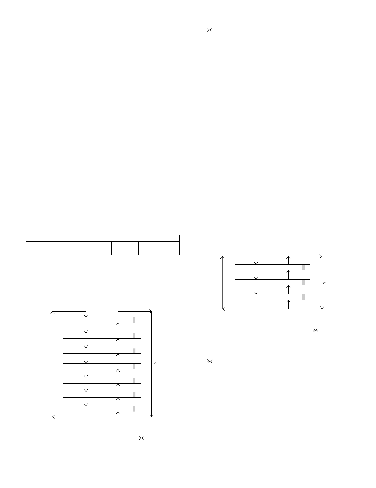
FO-DC635U
2.2.7 Rapid key 07: Paper feed aging 2
This is a mode that is used for aging related to printing, and there are
following modes. And also as to the print interval 5 sec. – 12 hour can
be set.
1. Print pattern
i) Blank paper
ii) All black
iii) 5% print pattern
iv) 4% print pattern
v) Outer frame check pattern
vi) 4% chart pattern
2. Print interval (Time between finishing and starting the printing.)
Settable range: 1 – 300 seconds
3. Number of print repetitions (Number of repetitions.)
Settable range: 125 – 1250 times
4. Number of printouts (Number of serial printings at a time.)
Settable range: 1 – 10 sheets
To execute, enter the above items with the ten keys after selecting the
mode. Refer to “Paper feed aging 1” for the details of print patterns. In
any of the mode, the operation will be interrupted only when the
“STOP” key is pressed by the operator, or an error which makes printing impossible occurs.
2.2.8 Rapid key 08: Bias adjust mode
The mode is used to adjust the printing density of the printed image.
The image printing density is adjustable in seven steps of 1 to 7. For
details, refer to the following table. (For selection, use the keys 1
through 7.)
Image printing density Thin ← → Thick
1234567
Default value {
3. After input of 6 digits, shift to another counter with the "#" and
" " keys as necessary. When all necessary counters are completely input, press the START key.
4. "STORED" will be displayed with the set values stored into the
memory. For checking, retry this mode.
NOTE: The counter shows the operational state of the printer (how
many sheets have been printed since start of use?). The ordinary
memory does not reset the counter. Accordingly, it is necessary to
reset this counter in addition to the ordinary memory clear if the content in the memory on the control PWB is broken because of PWB
repair, etc. (In the production stage, it is necessary to execute this in
the last process.)
2.2.10 Rapid key 10: Life all clear
The mode is used to clear the life counter of the printer of the counter
of the auto feeder.
NOTE: The counter shows the operational state of the printer (how
many sheets have been printed since start of use?). The ordinary
memory does not reset the counter. Accordingly, it is necessary to
reset this counter in addition to the ordinary memory clear if the content in the memory on the control PWB is broken because of PWB
repair, etc. (In the production stage, it is necessary to execute this in
the last process.)
2.2.11 Rapid key 11: Life entry mode
(For Serviceman temporary counter)
The mode is used to set a desired value for the judgment value (alarm
judgment counter value) of the general purpose life counters 1 through
3 of the printer. If the life of a consumable part (developer, imprinter,
etc) is set, the model which has the error display and RMS function will
inform RMS when the counter reaches the set value. For setting, proceed with the following procedure.
1. When the life counter setting mode is selected, the following will be
displayed.
2.2.9 Rapid key 09: Life set mode
The mode is used to set the life counter of the printer and the counter
of the auto feeder at desired values. For setting, proceed with the following procedure.
1. When the life counter setting mode is selected, the following will be
is displayed.
MACH I N E
DRUM
#key
FEEDER L I FE=
FEEDER L I FE= 001230
The cursor blinks at the top data.
Five counters can be selected with the “#” and " " keys.
2. In the state 1, input a desired setting number of 6 digits with the
ten-key.
LIFE
LIFE
L
IFE1
LIFE2
LIFE3
= 0123
0
001230
=
001230
=
001230
=
001230
=
001230
0
key
#key
LI FE1= 0000
LI FE2= 0000
LI FE3= 0000
0
0
0
0
0
0
key
The cursor blinks at the top data.
Three counters can be selected with the "#" and " " keys.
2. In the state 1, input a desired setting number of 6 digits with the
ten-key.
3. After input of 6 digits, shift to another counter with the "#" and
" " keys as necessary. When all necessary counters are completely input, press the START key.
4. "STORED" will be displayed with the set values stored into the
memory. For checking, retry this mode.
NOTE: The counter shows the operational state of the printer (how
many sheets have been printed since start of use?). The ordinary
memory does not reset the counter. Accordingly, it is necessary to
reset this counter in addition to the ordinary memory clear if the content in the memory on the control PWB is broken because of PWB
repair, etc. (In the production stage, it is necessary to execute this in
the last process.)
2 – 9
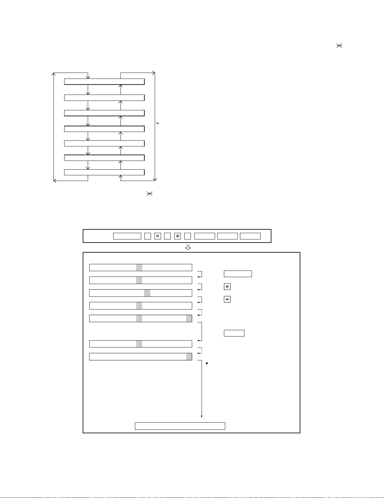
2.2.12 Rapid key 12: Life clear mode
The mode is used to respectively clear the life counter of the printer
and the counter of the auto feeder. For setting, proceed with the following procedure.
1. When the life counter clearing mode is selected, the following will
be is displayed.
MACH I N E
DRUM
L
#key
LIFE2
LIFE
LIFE
IFE1
C
LEAR
C
LEAR
C
LEAR
LEAR
C
key
FO-DC635U
2. In the state 1, input the DEL key, and the counter will be respectively cleared.
3. “CLEARED” is displayed and clearing is complete. After ending one
clear, move to another counter to clear with the "#" key, " " key,
if necessary. After clearing the necessary counter press down the
“STOP” key.
NOTE: The counter shows the operational state of the printer (how
many sheets have been printed since start of use?). The ordinary
memory does not reset the counter. Accordingly, it is necessary to
reset this counter in addition to the ordinary memory clear if the content in the memory on the control PWB is broken because of PWB
repair, etc. (In the production stage, it is necessary to execute this in
the last process.)
LIFE3
FEEDER L I FE LEAR
TONER L I FE L EAR
LEAR
C
C
C
Seven counters can be selected with the "#" and " " keys.
3. How to make soft switch setting
To enter the soft switch mode, make the following key entries in sequence.
Press
SFTSW1=00000000
SFTSW1=10000000
SFTSW1=10000000
SFTSW1=10000000
SFTSW1=10000000
MENU
9 8 7 STARTASTART
Press MENU key.
Press key.
Press key.
Bit1 - 8 are set.
• SW1 to SW22: For Line-1
• SW23 to SW44: For Line-2
SFTSW2=00000000
SFTSW99=00000000
The soft switch mode is terminated.
2 – 10
Press key during setting.
START
Soft SW2 - 99 are set.
To finish the settings halfway between
SW1 and SW99, press the STOP key.
In this case, the setting being done to
the SW No. on display will be nullified
while settings done to the preceding
SW No. remain in effect.
FO-DC635U
4. Soft switch description
4.1. Soft switch
• Soft switch (U: For U.S.A./C: For Canada)
SW
NO.
SW1
SW2
SW3
DATA
NO.
Recall interval 0
1
2
3
4
Recall times 0
5
6
7
8
1 Dial mode Pulse Tone 0 OPTION
2 Receive mode AUTO MANUAL 1
3 ECM mode Off On 0 OPTION
4Reserved 0
5 Polling security On Off 1 OPTION
6 Auto cover sheet No Yes 1 OPTION
7 JUNK-FAX function in man-
ual reception
8 JUNK-FAX function Yes No 0 OPTION
Number of rings for auto-
1
receive (0: No ring receive)
2
3
4
Switch to auto-receive from
5
manual receive (0: No
6
switch)
7
8
ITEM
Switch setting and function Initial
10
Binary input 8421
No.=1234(DataNo.)
EX 0101
eg. Recall interval is set to 5 min.
Binary input 8421
No.=5678(DataNo.)
EX 0010
eg. Recall times is set to 2 times.
Yes N o 0
Binary input 8421
No. = 1 2 3 4 (Data No.)
EX 0001
eg. Number of rings for auto receive is set to 1 time.
Binary input 8421
No. = 5 6 7 8 (Data No.)
EX 0000
eg. Switch to auto receive is set to disable.
setting
Remarks
OPTION
Set to 1~15
1
0
1
OPTION
Set to 0~14
0
1
0
0OPTION
0
0
1
0
0
0
0
Set to 0~9
OPTION
Set to 0~9
SW4
Communication results
printout
1
2
3
4 Image addition function to
the communication result
table (for memory transmis-
sion only)
5Reserved 0
6 TEL billing code function On Off 0 OPTION
7 Billing code position Before After 1 OPTION
8 Multi-TTI feature On Off 0 OPTION
Printed at error only 0 0 1
Printed at error/timer/ memory only 0 0 0
Printed at transmission mode only 0 1 0
Not printed 1 0 0
Printed every time 1 1 0
On Off 1 OPTION
No. 1 No. 2 No. 3
OPTION
0
0
1
2 – 11
Loading...