


Sennheiser EW135G3-G, EW135PG3-G, EW145G3-G, EW165G3-G, EW135PG3-A User manual
...
100 Series
Instruction manual

|
Contents |
Contents |
|
Important safety instructions ............................................................................................................................................................. |
2 |
System ............................................................................................................................................................................................... |
2 |
Receiver .............................................................................................................................................................................................. |
2 |
Bodypack transmitter and radio microphone ............................................................................................................................ |
3 |
The ew 100 G3 evolution wireless series ............................................................................................................................... |
........... 4 |
The frequency bank system ........................................................................................................................................................... |
4 |
Product overview .................................................................................................................................................................................... |
5 |
Overview of the EM 100 receiver .................................................................................................................................................. |
5 |
Overview of the displays of the EM 100 receiver ...................................................................................................................... |
6 |
Overview of the SK 100 bodypack transmitter ......................................................................................................................... |
7 |
Overview of the displays of the SK 100 bodypack transmitter .............................................................................................. |
8 |
Overview of the SKM 100 radio microphone .............................................................................................................................. |
9 |
Overview of the displays of the SKM 100 radio microphone ................................................................................................ |
10 |
Putting the devices into operation ................................................................................................................................................... |
11 |
EM 100 receiver .............................................................................................................................................................................. |
11 |
SK 100 bodypack transmitter ..................................................................................................................................................... |
13 |
SKM 100 radio microphone .......................................................................................................................................................... |
15 |
Using the devices .................................................................................................................................................................................. |
17 |
Switching the devices on/off ....................................................................................................................................................... |
17 |
Synchronizing a transmitter with the receiver ........................................................................................................................ |
20 |
Deactivating the lock mode temporarily ................................................................................................................................... |
21 |
Muting the audio signal or deactivating the RF signal ........................................................................................................... |
22 |
Selecting a standard display ........................................................................................................................................................ |
24 |
Overview of the operating menus .................................................................................................................................................... |
25 |
Cleaning the devices ............................................................................................................................................................................. |
27 |
Specifications ......................................................................................................................................................................................... |
31 |
Manufacturer Declarations ................................................................................................................................................................. |
35 |
For an animated instruction manual, visit the respective product pages at www.sennheiser.com.
There you will also find detailed instruction manuals for the individual devices.
1

Important safety instructions
Important safety instructions
System
•Read this instruction manual.
•Keep this instruction manual. Always include this instruction manual when passing the devices and the mains unit on to third parties.
•Heed all warnings and follow all instructions in this instruction manual.
•Only clean the devices when they are not connected to the mains. Use a cloth for cleaning.
•Only use attachments/accessories specified by Sennheiser.
•Refer all servicing to qualified service personnel.
Servicing is required if the devices or the mains unit have been damaged in any way, liquid has been spilled, objects have fallen inside, the devices have been exposed to rain or moisture, do not operate properly or have been dropped.
•WARNING: To reduce the risk of fire or electric shock, do not use the devices and the mains unit near water and do not expose them to rain or moisture.
Receiver
•Only use the supplied mains unit.
•Unplug the mains unit from the wall socket
–to completely disconnect the device from the mains,
–during lightning storms or
–when unused for long periods of time.
•Only operate the mains unit from the type of power source specified in the chapter “Specifications” (see page 31).
•Ensure that the mains unit is
–in a safe operating condition and easily accessible,
–properly plugged into the wall socket,
–only operated within the permissible temperature range,
–not covered or exposed to direct sunlight for longer periods of time in order to prevent heat accumulation (see “Specifications” on page 31).
•Do not block any ventilation openings. Install the device in accordance with the instructions given in this instruction manual.
•Do not install the device and the mains unit near any heat sources such as radiators, heat registers, stoves, or other devices (including amplifiers) that produce heat.
•Do not overload wall outlets and extension cables as this may result in fire and electric shock.
2

Important safety instructions
•Danger due to high volumes
This device is capable of producing sound pressure exceeding 85 dB(A). 85 dB(A) is the sound pressure corresponding to the maximum permissible volume which is by law (in some countries) allowed to affect your hearing for the duration of a working day. It is used as a basis according to the specifications of industrial medicine. Higher volumes or longer durations can damage your hearing. At higher volumes, the duration must be shortened in order to prevent hearing damage. The following are sure signs that you have been subjected to excessive noise for too long a time:
–You can hear ringing or whistling sounds in your ears.
–You have the impression (even for a short time only) that you can no longer hear high notes.
Bodypack transmitter and radio microphone
Do not place the devices near any heat sources such as radiators, heat registers, stoves, or other devices (including amplifiers) that produce heat.
Intended use of the system
Intended use of the ew 100 G3 series devices includes:
•having read this instruction manual especially the chapter “Important safety instructions”,
•using the devices within the operating conditions and limitations described in this instruction manual.
“Improper use” means using the devices other than as described in these instructions, or under operating conditions which differ from those described herein.
3

The ew 100 G3 evolution wireless series
The ew 100 G3 evolution wireless series
With the ew 100 G3 evolution wireless series, Sennheiser offers high-quality state-of-the-art RF transmission systems with a high level of operational reliability and ease of use. Transmitters and receivers permit wireless transmission with studio-quality sound.
The frequency bank system
Please note: Frequency usage is different for each country. Your Sennheiser partner will have all the necessary details on the available legal frequencies for your area.
The devices are available in 6 UHF frequency ranges with 1,680 frequencies per frequency range:
|
|
Range A: |
Range G: |
|
|
|
Range B: |
Range C: |
Range D: |
Range E: |
|||||
|
|
516 – 558 |
566 – 608 |
|
|
|
626 – 668 |
734 – 776 |
780 – 822 |
823 – 865 |
|
||||
500 |
|
600 |
700 |
|
800 |
MHz |
|||||||||
Each frequency range (A–E, G) offers 21 frequency banks with up to 12 channels each:
Channel 1 – frequency preset
Channel 2 – frequency preset
Frequency bank 1 ... 20
Channel 12 – frequency preset
Channel 1 – freely selectable frequency
Channel 2 – freely selectable frequency
Frequency bank U
Channel 12 – freely selectable frequency
Each of the channels in the frequency banks “1” to “20” has been factory-preset to a fixed frequency (frequency preset).
The factory-preset frequencies within one frequency bank are intermodulation-free. These frequencies cannot be changed.
For an overview of the frequency presets, please refer to the supplied frequency information sheet. Updated versions of the frequency information sheet can be downloaded from the product page on our website at www.sennheiser.com.
The frequency bank “U” allows you to freely select and store frequencies. It might be that these frequencies are not intermodulation-free.
4
Product overview
Product overview
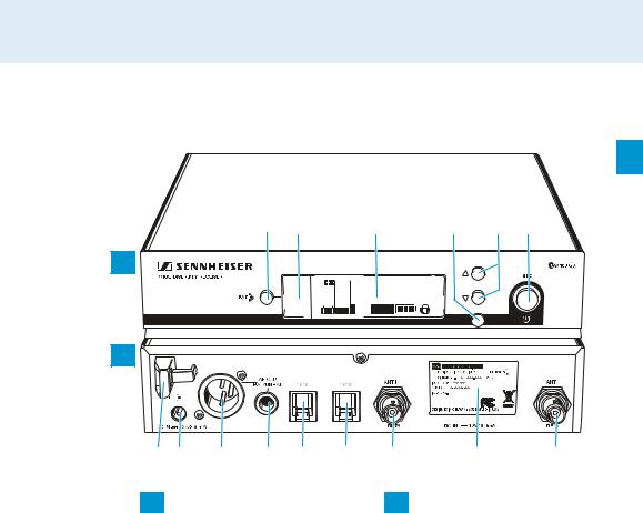
Overview of the EM 100 receiver
A
2 Data Ports auf der Rückseite ergänzen, Anzeigen-Display verkleinern, Jog-Dial entfernen, Typenschild zu 300 ändern, kein Kopfhörerausgang: Nr. anpassen
|
|
|
|
|
40 |
PEAK0 |
1. 1 |
ew100 G3 |
|
10 |
-20 |
543.200 |
MHz |
|
25 |
-10 |
|
|
|
RF |
-AF30 |
P MUTE |
|
|
|
|
|
|
SET |
B
A Operating elements – front panel

 button
Infra-red interface
Display panel, backlit in orange
SET button
UP/DOWN button
STANDBY button,
serves as the ESC (cancel) key in the operating menu
XXXXXXX

 0682
0682
B Operating elements – rear panel
Cable grip for power supply DC cable
DC socket (DC IN) for connection of NT 2 mains unit
Audio output (AF OUT BAL), XLR-3M socket, balanced
Audio output (AF OUT UNBAL), ¼” (6.3 mm) jack socket, unbalanced
Service interface (DATA)
Service interface (DATA)
Antenna input I (ANT II) with remote power supply input, BNC socket
Type plate
Antenna input I (ANT I) with remote power supply input, BNC socket
5
Product overview
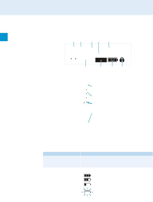
Overview of the displays of the EM 100 receiver
After switch-on, the receiver displays the standard display “Receiver Parameters”. For further illustrations and examples of the different standard displays, please refer to 24. This standard display displays the operating states of the receiver.
|
|
|
|
|
|
|
|
PEAK0 |
1. 1 |
EW100 G3 |
||||||
40 |
|
|
||||||||||||||
10 |
|
|
-20 |
|
543.200 |
MHz |
||||||||||
25 |
|
|
-10 |
|
|
|
|
|||||||||
|
|
|
|
|
|
|
|
|
-30 |
|
|
|
MUTE |
|
|
|
|
|
|
|
|
|
|
|
|
|
P |
|
|
|
|||
|
RF |
|
|
AF |
|
|
|
|
|
|||||||
|
|
|
|
|
|
|
|||||
|
|
|
|
|
|
|
|
|
|
|
|
Display |
Meaning |
|
|
|
|
||||||
RF level “RF” |
|
|
|
|
|
|
|
Diversity display: |
|
||
(Radio Frequency) |
|
|
|
|
|
|
|
|
Antenna input I is active |
||
|
|
|
|
|
|
|
|
|
|||
|
|
|
|
|
|
|
|
|
|||
|
|
|
40 |
|
|
|
|
Antenna input II is active |
|||
|
|
30 |
|
|
|
|
|||||
|
|
|
|
|
|
|
|
|
|||
|
|
|
|
|
RF signal level: |
|
|
||||
|
|
20 |
|
|
|
|
|
||||
|
|
10 |
|
|
|
Field strength of the transmitted signal |
|||||
|
|
|
|
|
|
|
|
Squelch threshold level |
|
||
|
|
|
RF |
|
|
|
|||||
|
|
|
|
|
|
|
|
|
|
|
|
Audio level “AF” |
|
PEAK |
|
Modulation of the transmitter |
|||||||
(Audio Frequency) |
|
|
with peak hold function. |
||||||||
0 |
|
|
|
||||||||
|
-10 |
|
|
|
When the level display for audio level shows full |
||||||
|
|
-20 |
|
|
|
deflection, the audio input level is excessively |
|||||
|
|
-30 |
|
|
|
high. When the transmitter is overmodulated |
|||||
|
-40 |
|
|
|
frequently or for extended periods of time, the |
||||||
|
|
AF |
|
|
“PEAK” display is shown inverted. |
||||||
|
|
|
|
||||||||
|
|
|
|
|
|
|
|
|
|
|
|
Frequency bank and |
Current frequency bank and channel number |
||||||||||
channel |
|
|
|
|
|
|
|
|
|
|
|
Frequency |
Current receiving frequency |
|
|||||||||
Name |
Freely selectable name of the receiver |
||||||||||
|
|
|
|
|
|
|
|
|
|
|
|
Pilot tone “P” Activated pilot tone evaluation
Muting function “MUTE” Receiver is muted
|
Receiver does not output an audio signal |
|
(see also page 28). |
|
|
Battery status of the |
Charge status: |
transmitter |
approx. 100% |
|
|
|
approx. 70% |
|
approx. 30% |
|
Icon is flashing; charge status is critical |
|
|
Lock mode icon |
Lock mode is activated |
|
|
6
Product overview
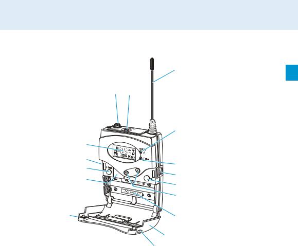
Overview of the SK 100 bodypack transmitter
|
|
|
|
|
|
|
|
|
|
|
|
|
|
|
|
|
|
|
|
|
|
|
|
|
|
|
|
|
|
|
|
|
|
|
|
|
|
|
Operating elements
Microphone/instrument input (MIC/LINE), 3.5 mm jack socket, lockable
MUTE switch
Antenna
Operation and battery status indicator, red LED (lit = ON/flashing = LOW BATTERY)
Audio overmodulation indicator, yellow LED (lit = AF PEAK)
Charging contacts
SET button
/ rocker button (UP/DOWN)
Battery compartment
Battery compartment cover
Battery compartment catches
Infra-red interface
ON/OFF button,
serves as the ESC (cancel) key in the operating menu
Display panel, backlit in orange
7
Product overview
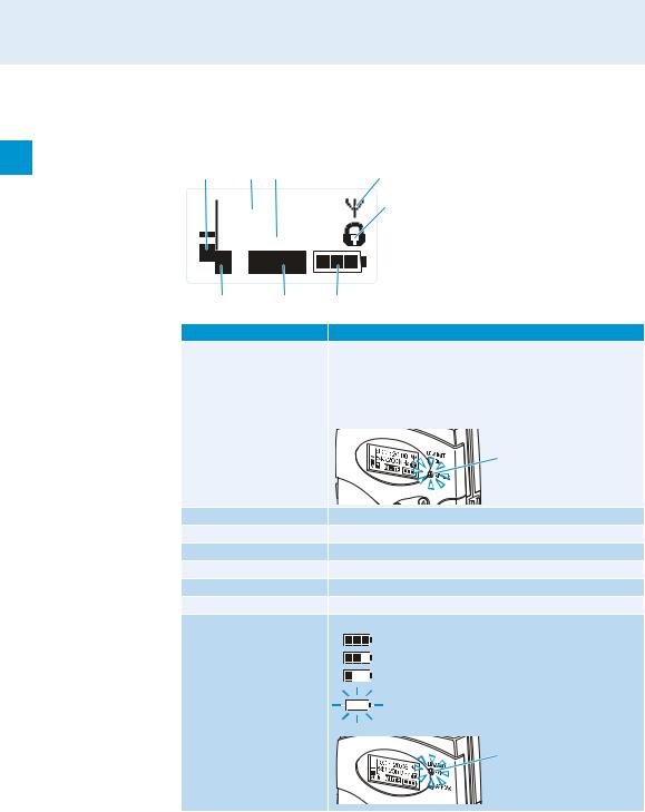
Overview of the displays of the SK 100 bodypack transmitter
After switch-on, the bodypack transmitter displays the standard display “Frequency/Name”. For further illustrations and examples of the different standard displays, refer to 24.
The display backlighting is automatically reduced after approx. 20 seconds.
|
|
543.200MHz |
|
|
|
ew100 G3 |
|
AF P MUTE
Display |
Meaning |
Audio level “AF” |
Modulation of the bodypack transmitter with peak hold |
|
function |
|
When the transmitter’s audio input level is excessively high, |
|
the “AF” display shows full deflection and, in addition, the |
|
yellow AF PEAK LED lights up: |
|
|
Frequency |
Current transmission frequency |
Name |
Freely selectable name of the bodypack transmitter |
Transmission icon |
RF signal is being transmitted |
Lock mode icon |
Lock mode is activated |
“P” (Pilot) |
Pilot tone transmission is activated |
“MUTE” |
Microphone or line input is muted |
Battery status |
Charge status: |
|
approx. 100% |
|
approx. 70% |
|
approx. 30% |
|
Charge status is critical, |
|
the red LOW BATT LED is flashing: |
|
|
8
Product overview
Overview of the SKM 100 radio microphone
Operating elements
Microphone head (interchangeable)
Name and pick-up pattern of the microphone head (not visible here)
Body of radio microphone
Battery compartment (not visible from outside)
Display panel, backlit in orange
Infra-red interface
Antenna
Color-coded protection ring; available in different colors
Operation and battery status indicator, red LED
(lit = ON/flashing = LOW BATTERY)
Charging contacts
Multi-function switch:
(DOWN), (UP) and  (SET)
(SET)
ON/OFF button,
serves as the ESC (cancel) key in the operating menu
9
Product overview
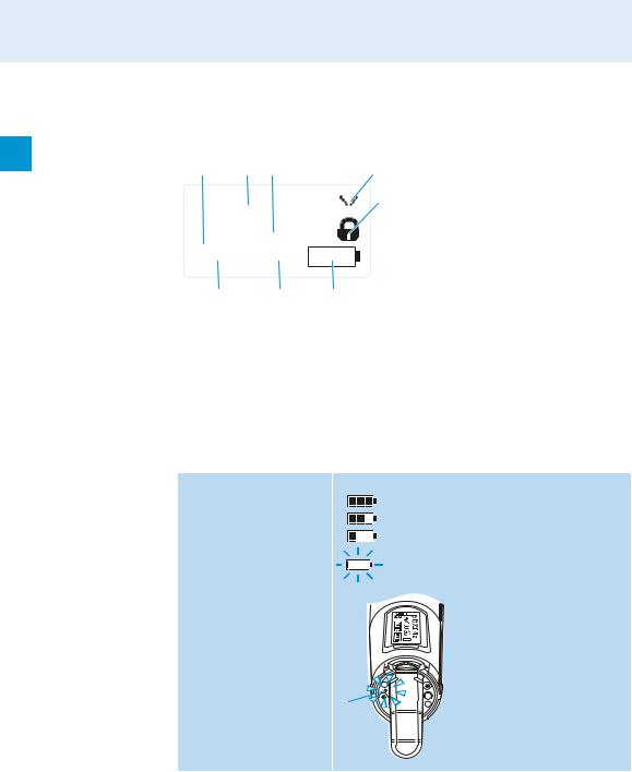
Overview of the displays of the SKM 100 radio microphone
After switch-on, the radio microphone displays the standard display “Frequency/Name”. For further illustrations and examples of the different standard displays, refer to 24.
The display backlighting is automatically reduced after approx. 20 seconds.
|
|
|
543.200MHz |
|
|
|
|
||||||
|
|
|
ew100 G3 |
|
|
|
|
|
|||||
|
|
|
|
|
|
|
|
||||||
|
|
|
|
|
|
|
|
||||||
|
|
|
|
|
|
|
|
|
|
|
|
|
|
|
|
|
P |
|
MUTE |
|
|
|
|
|
|
|
|
|
|
|
|
|
|
|
|
|
|
|
|||
AF |
|
|
|
|
|
|
|
|
|||||
|
|
|
|
|
|
|
|
|
|
||||
|
|
|
|||||||||||
|
|
||||||||||||
|
|
|
|
|
|
|
|
|
|
|
|
|
|
Display |
|
|
|
|
Meaning |
||||||||
Audio level “AF” |
|
Modulation of the radio microphone with peak hold |
|||||||||||
|
|
|
|
|
|
|
|
|
function |
||||
Frequency |
|
Current transmission frequency |
|||||||||||
Name |
|
|
|
|
Freely selectable name of the radio microphone |
||||||||
Transmission icon |
|
RF signal is being transmitted |
|||||||||||
Lock mode icon |
|
Lock mode is activated |
|||||||||||
“P” (Pilot) |
|
Pilot tone transmission is activated |
|||||||||||
“MUTE” |
|
|
|
|
Audio signal is muted |
||||||||
Battery status |
|
Charge status: |
|||||||||||
|
|
|
|
|
|
|
|
|
|
|
|
approx. 100% |
|
|
|
|
|
|
|
|
|
|
|
|
|
approx. 70% |
|
|
|
|
|
|
|
|
|
|
|
|
|
approx. 30% |
|
|
|
|
|
|
|
|
|
|
|
|
|
Charge status is critical, |
|
|
|
|
|
|
|
|
|
|
|
|
|
the red LOW BATT LED is flashing: |
|

10
 Loading...