


 Loading...
PLASMA DISPLAY TV
Chassis: F65A(P_FHD)_B530
Model : PS50B530S2WXXC
PS50B535S2WXXE
SERVICE Manual 
PLASMA DISPLAY TV |
CONTENTS |
1. |
Precaution |
2. |
Product Specification |
3. |
Disassembly & Reassembly |
4. |
Troubleshooting |
5. |
Exploded View & Part List |
6. |
Wiring Diagram |
PS50B530S2W
Refer to the service manual in the GSPN (see the rear cover) for the more information.

GSPN (Global Service Partner Network)
Area |
Web Site |
North America |
service.samsungportal.com |
Latin America |
latin.samsungportal.com |
CIS |
cis.samsungportal.com |
Europe |
europe.samsungportal.com |
China |
china.samsungportal.com |
Asia |
asia.samsungportal.com |
Mideast & Africa |
mea.samsungportal.com |
This Service Manual is a property of Samsung Electronics Co.,Ltd. Any unauthorized use of Manual can be punished under applicable International and/or domestic law.
©Samsung Electronics Co.,Ltd. May. 2009 Printed in Korea
AA82-05935A

Table of Contents
1. Precaution |
|
|
1-1 |
Safety Precautions....................................................................................................................................................... |
1-1 |
1-2 |
Servicing Precautions.................................................................................................................................................. |
1-3 |
1-3 |
Static Electricity Precautions........................................................................................................................................ |
1-4 |
1-4 |
Installation Precautions................................................................................................................................................ |
1-5 |
2. Product Specification |
|
|
2-1 |
Product Specification................................................................................................................................................... |
2-1 |
2-2 |
Specifications Analysis................................................................................................................................................. |
2-4 |
2-3 |
Accessories.................................................................................................................................................................. |
2-5 |
3. |
Disassembly & Reassembly |
|
|
|
3-1 Overall Disassembly & Reassembly............................................................................................................................ |
3-1 |
|
4. |
Troubleshooting |
|
|
|
4-1 |
Troubleshooting............................................................................................................................................................ |
4-1 |
|
4-2 |
Adjustment................................................................................................................................................................... |
4-8 |
|
4-3 |
Upgrade....................................................................................................................................................................... |
4-21 |
5. |
Exploded View & Part List |
|
|
|
5-1 |
PS50B530S2WXXC Exploded View............................................................................................................................ |
5-1 |
|
5-2 |
PS50B535S2WXXE Exploded View............................................................................................................................ |
5-3 |
|
5-3 |
PS50B530S2WXXC Service Item................................................................................................................................ |
5-5 |
|
5-4 |
PS50B535S2WXXE Service Item................................................................................................................................ |
5-6 |
6. |
Wiring Diagram |
|
|
|
6-1 |
Overall Wiring............................................................................................................................................................... |
6-1 |

Product Specification
2. Product Specification
2-1 Product Specification
Features
Block |
Specification |
|
Major IC |
|
Remark |
|
|
|
|
|
|
RF |
Digital/Analog (DTV Built In) |
|
Tuner |
|
|
|
DNOQ403SH151A SAMSUNG |
|
|
||
|
|
|
|
|
|
PDP Module |
Samsung SDI U1P Module |
|
50" FHD |
|
New Module |
|
|
|
|
|
|
Power |
Samsung electro mechanics SMPS |
|
|
|
|
Danam electronics SMPS 110V ~ 220V Free volt |
|
|
|
||
|
|
|
|
||
Video |
HDMI |
|
|
|
|
DNIe |
|
SEMS12 |
|
|
|
|
Component, PC |
|
|
|
|
|
|
|
|
|
|
Sound |
SRS TruSuround HD, Dolby Digital |
|
NTP3200 |
|
|
|
|
|
|
|
|
Cabinet |
B530 Design |
|
|
|
|
|
|
|
|
|
|
|
|
Specification |
|
||
|
|
|
|
||
Model |
|
PS50B530S2F |
|
||
|
|
|
|
||
Dimensions |
|
48.0x 2.9x 29.4 inches (without stand) |
|
||
(WxHxD) |
|
48.0 x 12.4 x 31.8 inches (with stand) |
|
||
Weight |
|
69.0 lbs (38.4kg) - with stand |
|
||
|
77.1 lbs (33.4kg) -without stand |
|
|||
|
|
|
|||
Voltage |
|
AC 100~240V, 60Hz 550W |
|
||
|
|
|
|
||
PC Resolution |
|
1920(H) x 1080(V) |
|
||
|
|
|
|
||
Screen Size |
|
50 inches (16:9) |
|
||
|
|
|
|
||
ANTENNA input |
|
ANT - AIR/CABLE IN |
|
||
|
75Ω unbalanced |
|
|||
|
|
|
|||
|
|
AV |
|
||
|
COMPONENT - 480i/480p/720p/1080i/1080p |
|
|||
|
COMPONENT2480i/480p/720p/1080i/1080p |
|
|||
VIDEO input |
|
PC |
|
||
|
HDMI1 : 480p/720p/1080i/1080p |
|
|||
|
|
|
|||
|
HDMI2(DVI Compatible) - 480p/720p/1080i/1080p |
|
|||
|
HDMI3(SIDE AV) - 480p/720p/1080i/1080p |
|
|||
|
480i can be displayed on HDMI, however it is not contained in EDID data |
|
|||
|
|
AV |
|
||
|
COMPONENT - 480i/480p/720p/1080i/1080p |
|
|||
AUDIO input |
COMPONENT2 - 480i/480p/720p/1080i/1080p |
|
|||
|
|
PC |
|
||
|
|
DVI |
|
||
Audio Output |
|
AUDIO (L/R) |
|
||
|
|
|
|
||
Speaker Output |
|
10W+10W (40dB+40dB |
|
||
|
|
|
|
||
New Features |
|
Anynet+ |
|
||
|
|
|
|
|
|
Samsung Electronics |
2-1 |

Product Specification
■ Sems03
The SEMS03 is a high performance and fully integrated IC for multi-function LCD monitor/TV with resolutions up to full HD (1920x1080). It is configured with an integrated triple-ADC/PLL, an integrated DVI/HDCP/HDMI receiver, a multi-standard TV video and audio decoder, two video de-interlacers, two scaling engines, the MStarACE-3 color engine frame buffer, PIP/POP is provided for multimedia applications. Furthermore,3-D video decoding and processing are fulfilled for high-quality TV applications. To further reduce system costs,the SEMS03 also integrates intelligent power management control capability for green-mode requirements and spread-spectrum support for EMI management.
■NTP-3200
The NTP-3200 is a single chip full digital audio amplifier including power stages for stereo amplifier system. NTP-3200 is integrated with versatile digital audio signal processing functions, high-fidelity fully digital PWM modulator and two high-power full bridge MOSFET stages. The NTP-3200 receives 2-channel serial audio data with sampling frequency from 8 kHz to 192 kHz. It delivers 2x20W in stereo mode without heat sink.
The NTP-3200 has mixer and biquad filters which can be used to implement the essential audio signal processing functions like loudness control, loud speaker response compensation and parametric equalizers.
All the functions of the NTP-3200 can be controlled by internal register values via I2C host interface bus.
■TMDS351
The TMDS351 is a 3-port digital video interface (DVI) or high-definition multimedia interface (HDMI) switch that allows up to 3 DVI or HDMI ports to be switched to a single display terminal. Four TMDS channels, one hot plug detector, and a digital display control (DDC) interface are supported on each port. Each TMDS channel supports signaling rates up to 2.5 Gbps to allow 1080p resolution in 12-bit color depth.
2-2 |
Samsung Electronics |
Product Specification
■New Features explanation
-WISELINK: This function enables you to view photo (JPEG) and listen to audio files (MP3) saved on a USB Mass Storage Class (MSC) device.
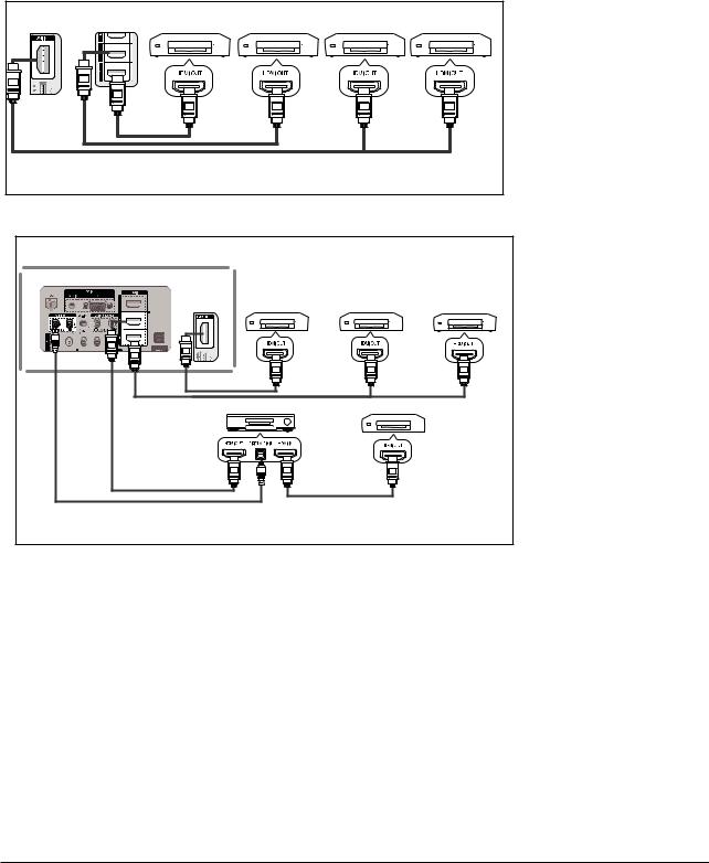
-Anynet+ : Anynet+ is an AV network system that enables you to control all connected Samsung AV devices with your Samsung TV’s remote.
To connect to a TV
TV |
Anynet + Device 1 |
Anynet + Device 2 |
Anynet + Device 3 |
Anynet + Device 4 |
|
||||
|
HDMI 1.3 Cable |
|
|
|
HDMI 1.3 Cable |
|
HDMI 1.3 Cable |
|
|
Connect the [HDMI 1], [HDMI 2], [HDMI 3] or [HDMI4] jack on the TV and the HDMI OUT jack of the corresponding Anynet+ device using an HDMI cable.
|
TV |
|
|
|
|
To connect to a Home Theater |
|
|
|
|
|
|
|
|
|
Anynet + Device 1 |
|
Anynet + Device 2 |
1 Connect the [HDMI 1], |
|
|
|
|
|
|
|
[HDMI 2] or [HDMI 3] |
|
|
|
|
|
|
jack on the TV and the |
|
|
|
|
|
|
HDMI OUT jack of the |
|
|
|
|
|
|
corresponding Anynet+ |
|
|
|
|
|
|
device using an HDMI |
|
HDMI 1.3 Cable |
HDMI 1.3 Cable |
HDMI 1.3 Cable |
cable. |
||
|
2 Connect the HDMI IN jack |
|||||
|
|
|
||||
|
|
Home Theater |
Anynet + Device 4 |
|||
|
|
|
|
|
|
of the home theater and |
|
|
|
|
|
|
the HDMI OUT jack of the |
|
|
|
|
|
|
corresponding Anynet+ |
|
|
|
|
|
|
device using an HDMI |
Optical |
HDMI 1.3 Cable |
|
HDMI 1.3 Cable |
cable. |
||
Cable |
|
|
|
|||
|
|
|
|
|
|
|
 Connect the Optical cable between the Digital Audio Out (Optical) jack on your TV and the Digital Audio Input on the Home Theater.
 Connect only one Home Theater.
 When following the connection above, the Optical jack only outputs 2 channel audio. You will only hear sound from the Home Theater’s Front Left and Right speakers and the subwoofer. If you want to hear 5.1 channel audio, connect the DIGITAL AUDIO OUT (OPTICAL) jack on the DVD player or Cable/Satellite Box (ie Anynet Device 1 or 2) directly to the Amplifier or Home Theater, not the TV. Please see the home theater’s user manual for more information.
 Some HDMI cables may not support Anynet+ functions.
 Anynet+ works when the AV device supporting Anynet+ is in the Standby or On status.
 Anynet+ supports up to 12 AV devices in total. Note that you can connect up to 3 devices of the same type.
Samsung Electronics |
2-3 |

Product Specification
2-2 SpecificationsAnalysis
|
|
|
|
|
: application, : non-application |
|
|
|
|
|
|
|
Model |
|
PS50B530S2F |
PS50A550S1 |
|
|
Design |
|
|
|
|
|
|
|
|
|
|
|
Display Type |
|
PDP TV |
PDP TV |
|
|
|
|
|
|
|
|
Built-In Tuner |
|
|
|
|
|
|
|
|
|
|
|
Resolution |
|
1920 x 1080 @60Hz |
1920 x 1080 @60Hz |
|
|
|
|
|
|
|
Basic |
PDP Module |
|
UF1A FHD |
W3.5F FHD |
|
|
|
|
|
|
|
Screen Size |
|
50 inches |
50 inches |
||
|
|
||||
|
|
|
|
|
|
|
Picture ratio |
16 : 9 |
|
16 : 9 |
|
|
|
|
|
|
|
|
Dimensions (WxHxD) |
|
1230.3 x 821.5 x 290.0 mm (With stand) |
1230.3 x 830.6 x 319.9 mm (With stand) |
|
|
|
|
|
|
|
|
Weight |
|
35 kg |
42.4 kg |
|
|
|
|
|
|
|
|
Brightness |
|
1,500 Cd/m2 |
1,000 Cd/m2 |
|
|
|
|
|
|
|
Picture |
Contrast Ratio |
10,000 : 1 |
|
10,000 : 1 |
|
|
|
|
|
|
|
|
Picture Enhacer |
|
X |
FBE3X |
|
|
|
|
|
|
|
|
Equalizer |
|
|
|
|
|
|
|
|
|
|
|
Auto Volume Control |
|
|
|
|
|
|
|
|
|
|
Audio |
Surround Sound |
|
SRS TruSurround |
SRS TruSurround |
|
|
|
|
|
|
|
|
Speaker Output |
|
10W + 10W |
10W + 10W |
|
|
|
|
|
|
|
|
Speaker |
|
2.2CH (2Way) |
2.2CH (2Way) |
|
|
|
|
|
|
|
|
PIP |
|
X |
|
|
|
|
|
|
|
|
|
Double Screen |
|
|
|
|
|
|
|
|
|
|
|
Caption |
|
|
|
|
|
|
|
|
|
|
Features |
Still Image |
|
|
|
|
|
|
|
|
|
|
My Color Control |
|
|
|
||
|
|
||||
|
|
|
|
|
|
|
Color Weakness |
|
|
|
|
|
|
|
|
|
|
|
Energy Saving |
|
|
|
|
|
|
|
|
|
|
|
Screen Burn Protection |
|
|
|
|
|
|
|
|
|
|
|
Antenna |
|
1 Input |
1 Input |
|
|
|
|
|
|
|
|
AV Input |
|
1 Input (Side) |
1 Input (Side) |
|
|
|
|
|
|
|
|
S-Video |
|
X |
1 Input (Side) |
|
|
|
|
|
|
|
|
Component (Y/PB/PR) |
|
2 Input |
|
2 Input |
Connections |
PC (D-SUB) |
|
1 Input |
1 Input |
|
|
|
|
|
|
|
DVI |
|
|
|
||
|
|
||||
|
|
|
|
|
|
|
HDMI |
|
3 Input |
3 Input |
|
|
|
|
|
|
|
|
Scart |
|
|
|
|
|
|
|
|
|
|
|
Optical |
|
|
|
|
|
|
|
|
|
|
|
Coaxial |
|
|
|
|
|
|
|
|
|
|
For the power supply and power consumption, refer to the label attached to the product.
2-4 |
Samsung Electronics |
2-3 Accessories
Accessories
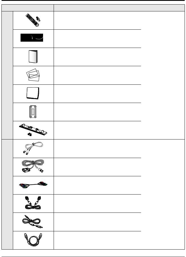
Supplied Accessories
Accessories that can be purchased additionally
Product Specification
Item |
Item code |
Remark |
Remote Control |
BN59-00863A |
|
Batteries |
4301-000103 |
|
Power Cord |
3903-000145 |
|
Owner’s Instructions |
BN68-02012A |
|
BN68-02012C |
|
|
|
|
|
Warranty Card |
BN68-00514E |
Samsung Service center |
Registration Card |
- |
|
Safety Guide Manual |
AA68-03242Q |
|
Cloth-Clean |
BN63-01798B |
|
Ferrite Core for |
3301-001305 |
|
Power Cord and |
|
|
|
|
|
Cover-Bottom |
BN63-05671A |
|
Screws (2ea) |
6003-001621 |
|
HDMI Cable |
BN39-00641A |
|
9.83 feet |
|
|
|
|
|
HDMI/DVI cable |
BN39-00643A |
|
9.83 feet |
|
|
|
|
|
Component Cables (RCA) |
BN39-00279A |
|
5 feet |
|
|
|
Electronics Store/ |
|
|
|
|
PC Cable |
|
Internal shopping mall |
BN39-00115A |
|
|
6 feet |
|
|
|
|
|
PC Audio Cable |
BN39-00061B |
|
6.5 feet |
|
|
|
|
|
Antenna Cable |
BN39-00333A |
|
9.83 feet |
|
|
|
|
|
|
|
|
Samsung Electronics |
2-5 |
Disassembly & Reassembly
3. Disassembly & Reassembly
3-1 Overall Disassembly & Reassembly
Notice
-Be sure to separate the power cord before disassembling the unit.
-Discharge the capacitors first when separating PCB’s with high capacity capacitors such as SMPS, X Main Board, Y Main Board, etc. (A spark may be generated by the electric charge, and there is danger of electronic shock.)
-Check that the cables are properly connected referring to the circuit diagram when disassembling or assembling the unit taking care not to damage the cables.
-Take care not to scratch the Glass Filter in the front.
-Assemble the boards in the reverse order of the disassembly.
-The plasma must be layed down on a flat padded surface for disassembly and reassembly.
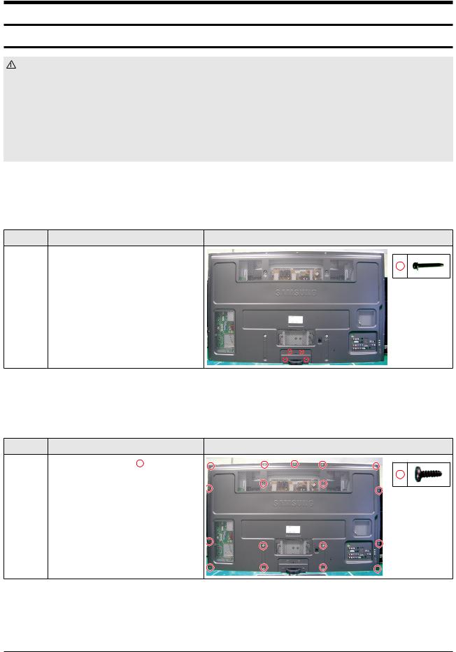
3-1-1 Separation of ASSY STAND P-BASE
Part Name |
Description |
Description Photo |
Stand Remove 4 screws.
:PH,+,WSP,S,M4,L40,ZPC(BLK),
SWRCH18A,
Pull the stand down to remove it from the unit.
 Please lay the PDP unit face down on a soft surface when removing the stand.
3-1-2 Separation of ASSY COVER P-REAR
Part Name |
Description |
Description Photo |
Cover |
Remove 17 screws. ( |
) |
Rear |
: BH,+,B,M4,L12,ZPC(BLK),SWRCH18 |
|
|
Remove the rear cover. |
|
Samsung Electronics |
3-1 |
Disassembly & Reassembly
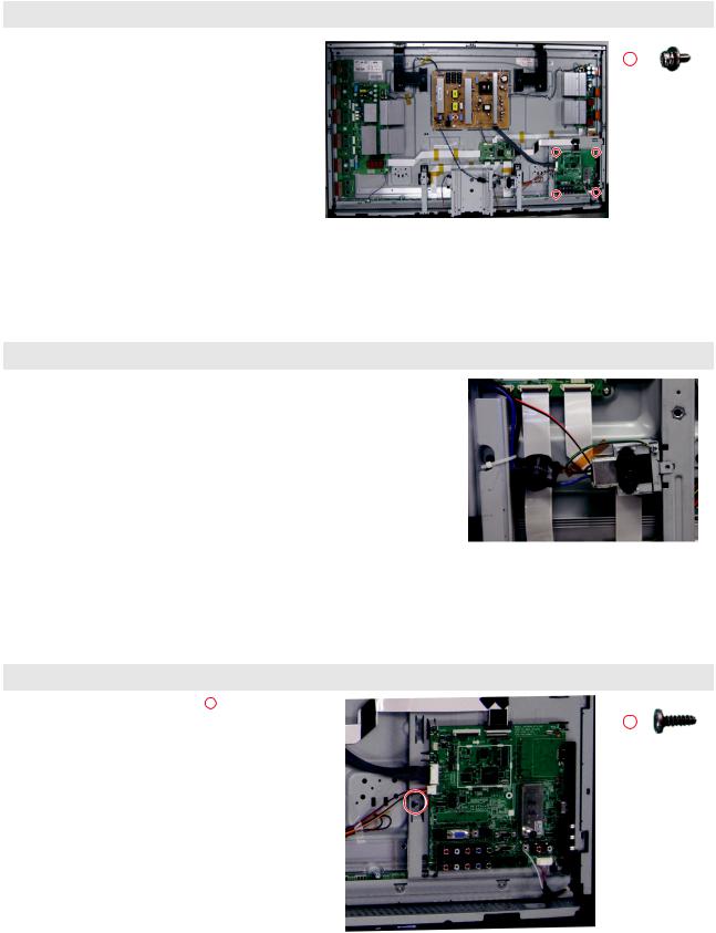
3-1-3 Separation of ASSY PCB MISC-MAIN
Part Name |
Description |
Description Photo |
|||
|
|
|
|
|
|
Main |
Detach all connectors from the Main |
|
|
|
|
|
|
|
|
||
Board |
Board. |
|
|
|
|
|
Remove 4 screws. |
|
|
|
|
|
|
|
|
|
|
|
: PH,+,WWP,M3,L8,NI PLT |
|
|
|
|
|
Remove the Main Board. |
|
|
|
|
|
|
|
|
|
|
3-1-4 Separation of FILTER-EMI AC LINE
Part Name |
Description |
Description Photo |
|
|
|
FILTER |
Detach connector from SMPS. |
|
EMI |
Remove FILTER-EMI AC LINE. |
|
AC LINE |
|
|
|
|
|
3-1-5 Separation of BRACKET-PCB
Part Name |
Description |
Description Photo |
|||
|
|
|
|
|
|
Bracket |
Remove 1 screws. ( ) |
|
|
|
|
|
|
|
|
||
PCB |
: BH,+,B,M4,L12,ZPC(BLK),SWRCH18 |
|
|
|
|
|
Remove BRACKET-PCB. |
|
|
|
|
|
|
|
|
|
|
|
|
|
|
|
|
|
|
|
|
|
|
3-2 |
Samsung Electronics |
Disassembly & Reassembly
3-1-6 Separation of ASSY BRACKET P-SUPPORT STAND
Part Name |
Description |
Description Photo |
|||
|
|
|
|
|
|
Bracket Remove 2 screws. |
|
|
|
|
|
|
|
|
|
||
Support |
: BH,+,PT,S Tite,M4,L10,ZPC(BLK), |
|
|
|
|
Stand |
SWRCH18A, Plastic washer |
|
|
|
|
|
|
|
|
||
Remove the BRACKET-SUPPORT STAND.
3-1-7 Separation of ASSY p-speaker
Part Name |
Description |
Description Photo |
|||
|
|
|
|
|
|
Holder |
Remove 4 screws. ( ) |
|
|
|
|
|
|
|
|
||
Module |
: BH,+,WP,B,M4.0,L,12,ZPC(BLK), |
|
|
|
|
|
SWRCH18A |
|
|
|
|
|
|
|
|
|
|
|
Remove p-speaker. |
|
|
|
|
|
|
|
|
|
|
3-1-8 Separation of HOLDER-MODULE
Part Name |
Description |
Description Photo |
|
Holder |
Remove 8 screws. ( |
) |
|
Module |
: FH,+,M3,L10,NI PLT,SWRCH18A,FP, |
|
|
|
Remove 8 screws. ( |
) |
|
: BH,+,B,M4,L12,ZPC(BLK),SWRCH18
Remove Holder Module.
 Please lay the PDP panel face down on a soft surface when separating front cover.
Samsung Electronics |
3-3 |

Disassembly & Reassembly
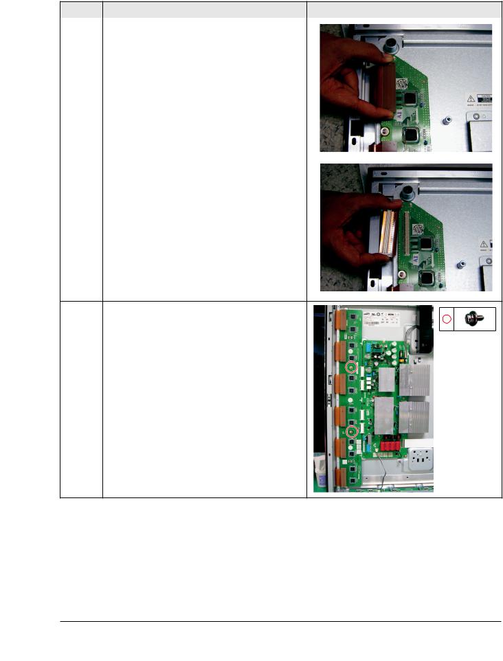
3-1-11 Separation of ASSY PDP MODULE P-X MAIN BOARD
Part Name |
Description |
Description Photo |
|
|
|
Flat Cable Detach all Connectors from the X-Main Board. |
|
|
|
To separate the Flat Cable of the X-Board, press the upper |
|
|
and the lower sides of the connector. |
|
X-Main |
Remove 4 screws. |
Board |
: PH,+,WWP,M3,L8,NI PLT,SWRCH18A |
|
Remove the X-Main Board. |
X-Buffer |
Remove 2 screws. |
Board |
: PH,+,WWP,M3,L8,NI PLT,SWRCH18A |
|
Remove the X-Buffer Board |
3-4 |
Samsung Electronics |
Disassembly & Reassembly
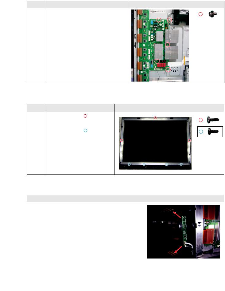
3-1-12 Separation of ASSY PDP MODULE P-Y MAIN BOARD
Part Name |
Description |
Description Photo |
|
|
|
Flat |
Detach the 6 scan board connectors from the panel by |
|
Cable |
pulling the holder from both the top and bottom ends. |
|
Y-Buffer |
Remove 2 screws. |
board. |
: PH,+,WWP,M3,L8,NI PLT,SWRCH18A |
|
Remove the Y-Buffer board. |
Samsung Electronics |
3-5 |
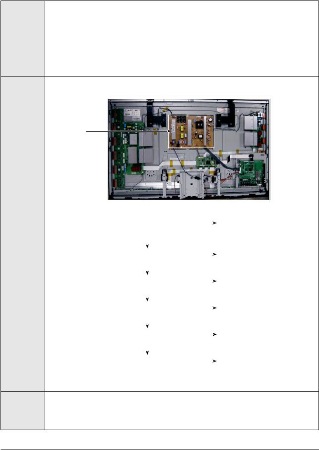
Disassembly & Reassembly
Part Name |
Description |
Description Photo |
|||
|
|
|
|
|
|
Y-Main Detach all connectors from the Y-Main Board. |
|
|
|
|
|
|
|
|
|
||
Board |
Remove 5 screws. |
|
|
|
|
|
|
|
|
|
|
|
: PH,+,WWP,M3,L8,NI PLT, SWRCH18A |
|
|
|
|
Remove the Y-Main Board and Y-Buffer board.
3-1-13 Separation of ASSY PANEL BRACKETS
Part Name |
Description |
Description Photo |
||||
|
|
|
|
|
|
|
Panel |
Remove 3 screws. ( |
) |
|
|
|
|
|
|
|
|
|||
Brackets |
: BH,+,B,M4,L3,ZPC(BLK) |
|
|
|
|
|
|
Remove 4 screws. ( |
) |
|
|
|
|
|
|
|
|
|
||
: BH,+,S,M4,L10,ZPC(BLK)
Remove the Side Panel Brackets.
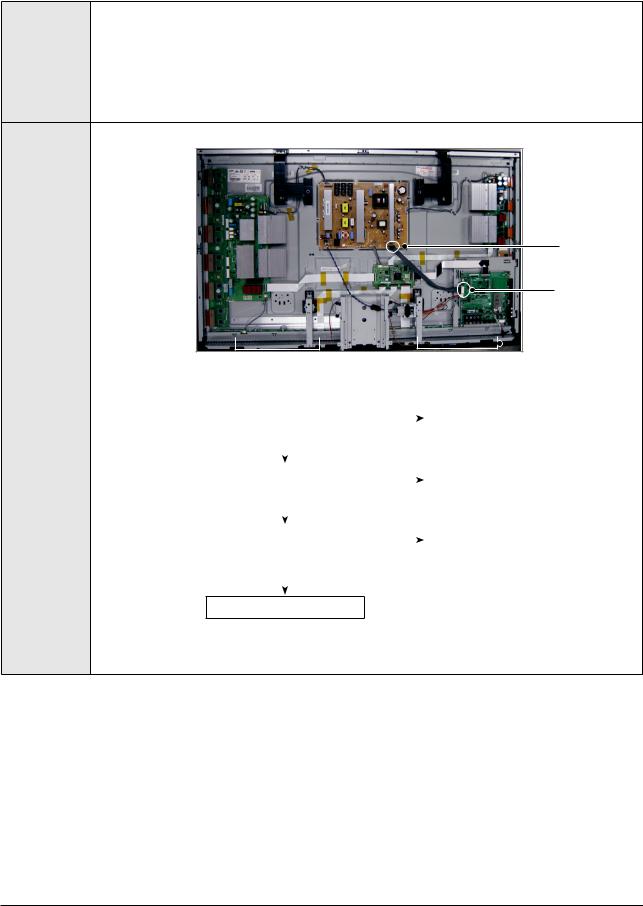
3-1-14 Separation of ASSY PCB FUNCTION
Part Name |
Description |
Description Photo |
|
|
|
Function |
Detach the all connectors from the buffer board. |
|
Board |
Remove the Function Board. |
|
|
|
|
|
|
|
|
|
|
3-6 |
Samsung Electronics |

Troubleshooting
4. Troubleshooting
4-1 Troubleshooting
4-1-1 First Checklist for Troubleshooting
1.Check the various cable connections first.
-Check to see if there is a burnt or damaged cable.
-Check to see if there is a disconnected or loose cable connection.
-Check to see if the cables are connected according to the connection diagram.
2.Check the power input to the Main Board.
3.Check the voltage in and out between the SMPS ↔ Main Board, between the SMPS ↔ X, Y Main Board, and between the
Logic Boards.
Samsung Electronics |
4-1 |

Troubleshooting
4-1-2 Checkpoints by Error Mode
■ No Power
|
- The LEDs on the front panel do not work when connecting the power cord. |
Symptom |
- The SMPS relay does not work when connecting the power cord. |
|
- The unit appears to be dead. |
|
|
|
The SMPS relay or the LEDs on the front panel does not work when connecting the power cord if the cables |
Major |
are improperly connected or the Main Board or SMPS is not functioning. In this case, check the following: |
- Check the internal cable connection. |
|
Checklist |
- Check the fuses. |
|
- Check the output voltages of the SMPS. |
|
- Replace the Main Board. |
3
2 |
4 |
|
5
1
|
|
No |
|
||
Check that the AC power cord is connected |
|||||
Connect the AC power cord |
|||||
|
|
||||
|
|
||||
Troubleshooting |
|
Yes |
Procedures |
|
|
|
|
|
If LED is set up as being ON when |
No |
|
|||
|
POWER-ON, check the ligt-on in LED |
|
|
Replace Fuse (FE801) |
||
|
|
|
||||
|
|
Yes |
No |
|
||
|
|
|
||||
|
|
|
||||
Is the AC Inlet socket connected? |
|
|||||
Connect AC Inlet socket |
||||||
|
|
|
|
|||
|
|
Yes |
No |
|
||
|
|
|||||
|
|
|
||||
|
|
|
||||
Check the connection between Fuse |
Replace Fuse |
|||||
F801S, for checking SMPS’s Fuse |
|
|
||||
|
|
|
||||
|
|
|
|
|
|
|
|
|
Yes |
|
|
|
|
|
|
|
No |
|
||
|
|
|
||||
Check the No. 4 STAND-BY power of |
Replace the SMPS |
|||||
|
|
|||||
CN801 |
|
|
||||
|
|
|
||||
|
|
|
|
|
|
|
Yes
Replace the Main Board
4-2 |
Samsung Electronics |
Troubleshooting
■ When the unit is repeatedly turning on and off
Symptom |
- The SMPS relay is repeatedly turning on and off. |
|
|
|
In general, the SMPS relay repeatedly turns on and off by the protection function due to a defect on a board |
|
connected to the SMPS. |
Major Checklist |
- Disconnect all cables from the SMPS, operate the SMPS alone and check if the SMPS works properly and if |
each voltage output is correct. |
|
|
- If the symptom continues even when SMPS is operating alone, replace the SMPS. |
|
- If the symptom is not observed when operating the SMPS alone, find any defective assemblies by |
|
connecting the cables one by one. |
1
|
|
Check that the Va,Vs voltage of SMPS |
No |
|
|||
|
Tune the Va, Vs or Replace the |
||||||
|
match the voltages marked on the module |
|
|
|
|||
Troubleshooting |
|
|
|
SMPS |
|||
|
label |
|
|
|
|
||
|
|
|
|
|
|||
Procedures |
|
|
Yes |
|
|
|
|
|
|
|
|
No |
|
|
|
|
|
|
|
|
|
||
|
|
Did problem improve? |
|
Replace the Main Board |
|||
|
|
|
|
|
|||
|
|
|
|
|
|||
|
|
|
|
|
|
|
|
|
|
|
Yes |
|
|
|
|
|
|
|
|
No |
|
|
|
|
|
|
|
|
|
||
|
|
Did problem improve? |
|
Y Main Board cable check or |
|||
|
|
|
|
|
|||
|
|
|
|
|
Replace the SMPS |
||
|
|
|
|
|
|
|
|
|
|
|
Yes |
No |
|
|
|
|
|
|
|
|
|
||
|
|
|
|
|
|
||
|
|
Did problem improve? |
|
X Main Board cable check or |
|||
|
|
|
|
|
|||
|
|
|
|
|
Replace the SMPS |
||
|
|
|
|
|
|
|
|
|
|
|
Yes |
No |
|
|
|
|
|
|
|
|
|
||
|
|
|
|
|
|
||
|
|
Did problem improve? |
|
Logic Board cable check or Replace |
|||
|
|
|
|
|
|||
|
|
|
|
|
the SMPS |
||
|
|
|
|
|
|
|
|
|
|
|
Yes |
No |
|
|
|
|
|
|
|
|
|
||
|
|
|
|
|
|
||
|
|
Did problem improve? |
|
Replace the X, Y Buffer Board |
|||
|
|
|
|
|
|||
|
|
|
|
|
|||
|
|
|
|
|
|
|
|
When separating and connecting the cables such as CN800,CN801,CN802,CN803, CN804 of the MAIN
Caution SMPS,CN4005 of the X MAIN Board, and CN5005 of the Y MAIN Board, a spark may be generated by the electric charge of the high capacity capacitor. Therefore, wait some time after disconnecting the power cord
from the unit.
Samsung Electronics |
4-3 |
Troubleshooting
■ No Sound
Symptom |
- |
Video is normal but there is no sound. |
|
|
|
|
Generally there are four things that can cause this issue. |
|
Major Checklist |
- |
Speakers not connected |
- |
Speakers are defective |
|
|
- Main board audio error |
|
|
- SMPS not supplying voltage to the main board |
|
2
1
3


 3
3
Troubleshooting |
|
|
|
|
|
|
Procedures |
|
|
|
No |
|
|
Is the cable connection between the Main |
Make the connection |
|||||
|
Board and the speaker properly connected? |
|
|
|||
|
|
|
|
|||
|
|
|
|
|
|
|
|
|
|
Yes |
|
|
|
|
|
|
|
|
||
|
|
|
|
No |
|
|
|
Check that the voltage on pins 7 & 8 of |
Replace the SMPS |
||||
|
|
|
||||
|
CN801 has 12V |
|
|
|||
|
|
|
|
|||
|
|
|
|
|
|
|
|
|
|
Yes |
|
|
|
|
|
|
|
|
||
|
|
|
|
No |
|
|
|
|
Use an oscilloscope to monitor the output |
Replace the Main Board |
|||
|
|
of the speaker jack. Does the wave form |
|
|
||
|
|
|
|
|||
|
|
|
|
|
||
|
|
match the wave form listed? |
|
|
|
|
|
|
|
|
|
||
|
|
|
|
|
|
|
|
|
|
Yes |
|
|
|
|
|
|
|
|
|
|
Replace the Speaker
4-4 |
Samsung Electronics |
Loading...