


 Loading...
Plasma TV
Chassis |
F86A |
Model Code |
PS51D6900DSXXC |
SERVICEMANUAL
Plasma TV
PS51D6900DS
Refer to the service manual in the GSPN (see the rear cover) for more information.
1. Precaution
1. Precaution
To avoid possible damage, electric shocks or exposure to radiation, follow the instructions below with regard to safety, installation, service and ESD.
1.1. Safety Precautions
1)Make sure all protective devices are properly installed including non-metallic handles and compartment covers when installing or re-installing the chassis or chassis assemblies.
2)Make sure that no gaps exist between the cabinets for children to insert their fingers in to prevent children from receiving electric shocks. Gaps mentioned above include ventilation holes of a too great magnitude between the PDP module and the cabinet mask, and the improper installation of the rear cabinet.
Errors may occur when the resistance is below 1.0MΩ or over 5.2MΩ. In these cases, make sure that the device is repaired before sending it back to the customer.
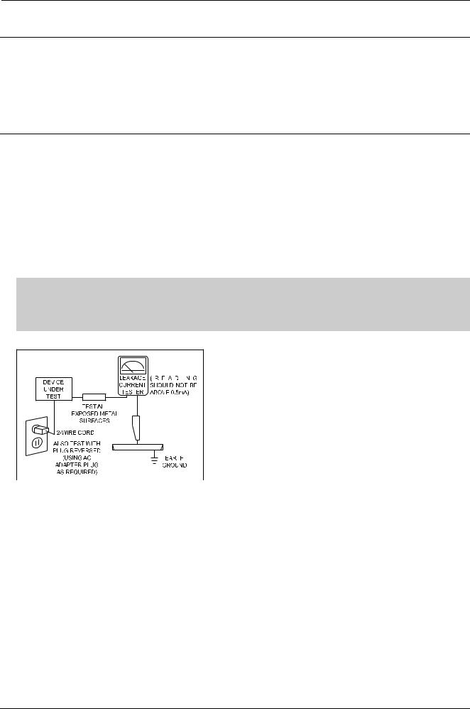
3)Check for Electricity Leakage (AC Leakage Test)
 WARNING
Do not use an insulated transformer for checking the leakage. Use only those current leakage testers or mirroring systems that comply with ANSIC 101.1 and the Underwriter Laboratory’s specifications (UL1410, 59.7).
Figure 1.1 AC Leakage Test
4)A high voltage is maintained within the specified limits using safety parts, calibration and tolerances. When voltage exceeds the specified limits, check each special part.
5)Warning for Engineering Changes:
Never make any changes or additions to the circuit design or the internal part for this product. Ex: Do not add any audio or video accessory connectors. This might cause physical damage.
Furthermore, any changes or additions to the original design/engineering will invalidate the warranty.
6)Warning - Hot Chassis:
Some TV chassis are directly connected to one end of the AC power cord for electrical reasons. Without insulated transformers, the product can only be repaired safely when the chassis is connected to the earthed end of the AC power source.
To make sure the AC power cord is properly connected, follow the instructions below. Use the voltmeter to measure the voltage between the chassis and the earthed ground. If the measurement is over 1.0V, unplug the AC power cord and change the polarity before reinserting it. Measure the voltage between the chassis and the ground again.
Copyright© 1995-2011 SAMSUNG. All rights reserved. |
1-1 |

1. Precaution
7)Some TV chassis are shipped with an additional secondary grounding system. The secondary system is adjacent to the AC power line. These two grounding systems are separated in the circuit using an unbreakable/unchangeable insulation material.
8)When any parts, material or wiring appear overheated or damaged, replace them with new regular ones immediately. When any damage or overheating is detected, correct this immediately and make a regular check of possible errors.
9)Check for the original shape of the lead, especially that of the antenna wiring, any sharp edges, the AC power and the high voltage power. Carefully check if the wiring is too tight, incorrectly placed or loose. Never change the space between the part and the printed circuit board. Check the AC power cord for possible damages. Keep the part or the lead away from any heat-emitting materials.
10)Safety Indication:
Some electrical circuits or device related materials require special attention to their safety features, which cannot be viewed by the naked eye. If an original part is replaced with another irregular one, the safety or protective features will be lost even if the new one has a higher voltage or more watts.
Critical safety parts should be bracketed with (  ,
,  ). Use only regular parts for replacements (in particular, flame resistance and dielectric strength specifications). Irregular parts or materials may cause electric shock or fire.
1-2 |
Copyright© 1995-2011 SAMSUNG. All rights reserved. |

1. Precaution
1.2. Servicing Precautions
 WARNING
1)First carefully read the “Safety Instruction” in this service manual.
When there is a conflict between the service and the safety instructions, follow the safety instruction at all times.
2)Any electrolytic capacitor with the wrong polarity will explode.
1)The service instructions are printed on the cabinet, and should be followed by any service personnel.
2)Make sure to unplug the AC power cord from the power source before starting any repairs.
a)Remove or re-install parts or assemblies.
b)Disconnect the electric plug or connector, if any.
c)Connect the test part in parallel with the electrolytic capacitor.
3)Some parts are placed at a higher position than the printed board. Insulated tubes or tapes are used for this purpose. The internal wiring is clamped using buckles to avoid contact with heat emitting parts. These parts are installed back to their original position.
4)After the repair, make sure to check if the screws, parts or cables are properly installed. Make sure no damage is caused to the repaired part and its surroundings.
5)Check for insulation between the blade of the AC plug and that of any conductive materials (i.e. the metal panel, input terminal, earphone jack, etc).
6)Insulation Check Process:
Unplug the power cord from the AC source and turn the switch on. Connect the insulating resistance meter (500V) to the AC plug blade. The insulating resistance between the blade of the AC plug and that of the conductive material should be more than 1MΩ.
7)Any B+ interlock should not be damaged.
If the metal heat sink is not properly installed, no connection to the AC power should be made.
8)Make sure the grounding lead of the tester is connected to the chassis ground before connecting to the positive lead. The ground lead of the tester should be removed last.
9)Beware of risks of any current leakage coming into contact with the high-capacity capacitor.
10)The sharp edges of the metal material may cause physical damage, so protect yourself by wearing gloves during the repair.
11)Due to the nature of plasma display panels, partial after-images may appear if a still picture is displayed on the screen for a long period of time.
This is caused by brightness deterioration due to the storage effect of the panel, and to prevent this from happening, we recommend that the brightness and contrast are reduced. (e.g.) Contrast: 25, Brightness: 50
Copyright© 1995-2011 SAMSUNG. All rights reserved. |
1-3 |

1. Precaution
1.3. Static Electricity Precautions
1)Some semi-conductive (“solid state”) devices are vulnerable to static electricity. These devices are known as ESD. ESD includes the integrated circuit and the field effect transistor. To avoid any materials damage from electrostatic shock, follow the instructions described below.
2)Remove any static electricity from your body by connecting the earth ground before handling any semi-conductive parts or assemblies. Alternatively, wear a dischargeable wrist-belt.
(Make sure to remove any static electricity before connecting the power source - this is a safety instruction for avoiding electric shock)
3)Remove the ESD assembly and place it on a conductive surface such as aluminum foil to prevent accumulating static electricity.
4)Do not use any Freon-based chemicals. Such chemicals will generate static electricity that causes damage to the ESD.
5)Use only grounded-tip irons for soldering purposes.
6)Use only anti-static solder removal devices.
Most solder removal devices do not support an anti-static feature. A solder removal device without an anti-static feature can store enough static electricity to cause damage to the ESD.
7)Do not remove the ESD from the protective box until the replacement is ready. Most ESD replacements are covered with lead, which will cause a short to the entire unit due to the conductive foam, aluminum foil or other conductive materials.
8)Remove the protective material from the ESD replacement lead immediately after connecting it to the chassis or circuit assembly.
9)Take extreme caution in handling any uncovered ESD replacements. Actions such as brushing clothes or lifting your leg from the carpet floor can generate enough static electricity to damage the ESD.
 CAUTION
These servicing instructions are for use by qualified service personnel only.
To reduce the risk of electric shock do not perform any servicing other than that contained in the operating instructions unless you are qualified to do so.
1-4 |
Copyright© 1995-2011 SAMSUNG. All rights reserved. |
1. Precaution
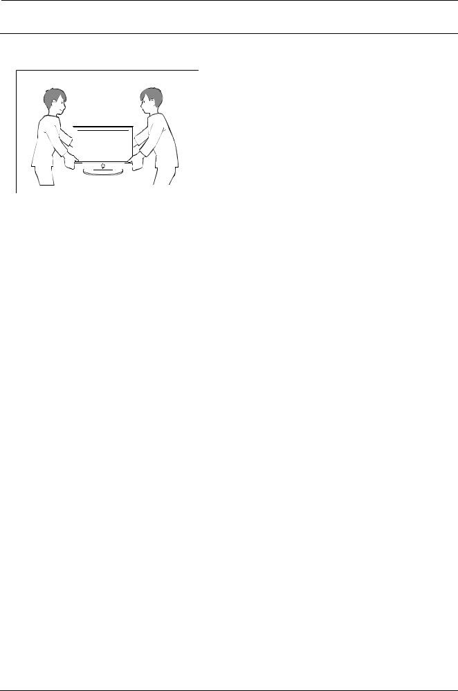
1.4. Installation Precautions
1) For safety reasons a minimum of two people are required to carry this product.
2)Keep the power cord away from any heat emitting devices, as a melted covering may cause fire or electric shock.
3)Do not place the product in areas with poor ventilation such as a bookshelf or closet. The increased internal temperature may cause fire.
4)Bend the external antenna cable when connecting it to the product. This is a measure to protect it from being exposed to moisture. Otherwise, it may cause a fire or electric shock.
5)Make sure to turn the power off and unplug the power cord from the outlet before repositioning the product. Also check the antenna cable or the external connectors if they are fully unplugged. Damage to the cord may cause fire or electric shock.
6)Keep the antenna far away from any high-voltage cables and install it firmly. Contact with the high-voltage cable or the antenna falling over may cause fire or electric shock.
7)When connecting the RF antenna, check for a DTV receiving system and install a separate DTV reception antenna for areas with no DTV signal.
8)When installing the product, leave enough space (4”) between the product and the wall for ventilation purposes. A rise in temperature within the product may cause fire.
9)When moving a PDP with removable speakers, detach the speakers first before moving the main body. Moving the PDP main body without separating the speakers may cause the speakers to detach, possibly causing damage or injury.
Copyright© 1995-2011 SAMSUNG. All rights reserved. |
1-5 |

2. Product Specification
2. Product Specification
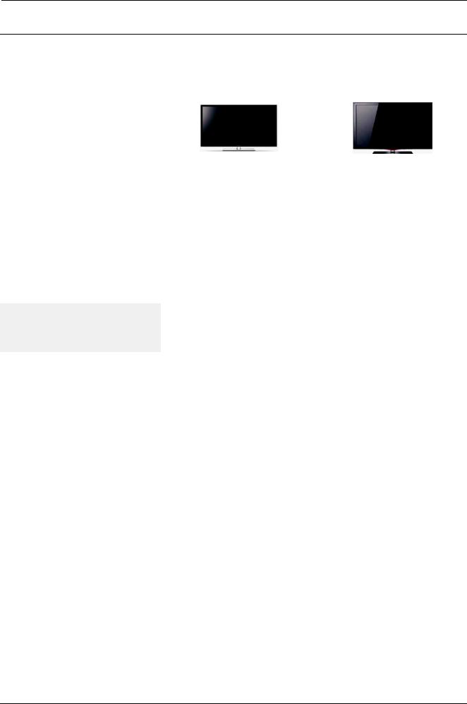
2.1. Appearance Specifications
|
Series |
PD6*** / PD7000 |
||
|
Design |
|
||
|
|
|
|
|
|
Front Color |
Brushed Black |
||
|
51" |
Without Stand |
47.1 X 1.5 X 28.3 |
|
|
|
|
||
Dimensions |
With Stand |
47.1 X 12.0 X 30.8 |
||
|
||||
|
|
|
||
59" |
Without Stand |
54.3 X 1.5 X 32.6 |
||
W x D x H |
||||
|
|
|||
With Stand |
54.3 X 13.2 X 34.9 |
|||
(inch) |
|
|||
|
|
|
||
64" |
Without Stand |
58.6 X 1.5 X 35.0 |
||
|
||||
|
|
|
||
|
With Stand |
58.6 X 13.2 X 37.3 |
||
|
|
|||
|
|
|
|
|
|
51" |
Without Stand |
49.3 |
|
|
|
|
||
|
With Stand |
59.6 |
||
|
|
|||
|
|
|
|
|
Weight |
59" |
Without Stand |
67.3 |
|
(lbs) |
With Stand |
79.8 |
||
|
||||
|
|
|
|
|
|
64" |
Without Stand |
77 |
|
|
|
|
||
|
With Stand |
89.5 |
||
|
|
|||
|
|
|
|
|
|
Feature |
CONTENT |
||
|
|
|
|
|
Copyright© 1995-2011 SAMSUNG. All rights reserved. |
2-1 |
2. Product Specification
2.2. Feature & Specifications
■Features
•Digital-TV, RF, 4-HDMI, 1-Component (AV), 2-USB 2.0 (Media Play), Optical, Lan
•Brightness : 1500 cd/m2
•Contrast Ratio : 10000:1
•Dolby Digital+, SRS theater
■Specification
Model |
P*51D6***D |
|
|
P*59D6***D |
|
P*64D7000D |
||
PDP Panel |
|
|
|
Clear Image Panel |
|
|||
Scanning Frequency |
Horizontal : 60 kHz ~ 73 kHz (Automatic) |
|||||||
Vertical : 47 Hz ~ 63 Hz (Automatic) |
||||||||
|
||||||||
Display Colors |
|
|
|
16.7M color |
|
|||
Maximum resolution |
|
|
|
Horizontal : |
1920 Pixels |
|
||
|
|
|
Vertical : |
1080 Pixels |
|
|||
|
|
|
|
|
||||
Input Signal |
Analog 0.7 Vp-p ± 5% positive at 75Ω, internally terminated |
|||||||
Input Sync Signal |
|
|
|
H/V Separate, TTL, P. or N. |
|
|||
Maximum Pixel Clock rate |
|
|
|
74.25 MHz |
|
|||
AC Power Voltage & |
|
|
|
AC 110V ~ 120V, 60 Hz |
|
|||
Frequency |
|
|
|
|
||||
|
|
|
|
|
|
|
||
Power Consumption |
|
Under 280 W (Under 1W, Stand by) |
||||||
|
with stand |
|
|
with stand |
|
with stand |
||
Dimensions Set |
47.1 X 12.0 X 30.8 inches |
|
54.3 X 13.2 X 34.9 inches |
|
58.6 X 13.2 X 37.3 inches |
|||
(W x D x H) |
without stand |
|
|
without stand |
|
without stand |
||
|
47.1 X 1.5 X 28.3 inches |
|
|
54.3 X 1.5 X 32.6 inches |
|
58.6 X 1.5 X 35.0 inches |
||
|
with stand |
|
|
with stand |
|
with stand |
||
Weight (Set) |
59.6 lbs |
|
|
79.8 lbs |
|
89.5 lbs |
||
|
|
|
|
|
|
|
||
without stand |
|
|
without stand |
|
without stand |
|||
|
|
|
|
|||||
|
49.3 lbs |
|
|
67.3 lbs |
|
77 lbs |
||
|
|
|
|
|
|
|||
|
Tuning |
|
|
Frequency Synthesize (Refer to detailed Frequency Table) |
||||
TV System |
|
|
|
|
|
|||
System |
|
|
ATSC & Clear QAM |
|
||||
|
|
|
|
|
|
|||
|
Sound |
|
|
NTSC-M, Dolby Digital + |
|
|||
|
Operating Temperature: 32˚F ~ 122˚F (0˚C ~ 50˚C) |
|||||||
Environmental |
|
|
Operating Humidity: 20% ~ 90% |
|
||||
Considerations |
Storage Temperature: -4˚F ~ 140˚F (-20˚C ~ 60˚C) |
|||||||
|
|
|
Storage Humidity: 10% ~ 90% |
|
||||
|
MAX Internal Audio Output Power : Each 3W (Left/Right) |
|||||||
Audio Spec. |
|
|
|
Equalizer : 5 band |
|
|||
Output Frequency : RF : 20 Hz ~ 15.4 kHz |
||||||||
|
||||||||
|
AV/Componet/HDMI : 20 Hz ~ 20 kHz |
|||||||
Others |
Dolby Digital +, Game Mode, Film Mode, Energy Saving, Anynet+ |
|||||||
|
|
|
|
|
|
|
|
|
2-2 |
Copyright© 1995-2011 SAMSUNG. All rights reserved. |
2. Product Specification
2.3. Specifications Analysis
|
|
|
P*51D6*** / P*51D7000 |
|
Model |
|
P*59D6*** / P*59D7000 |
P*50C7000 |
|
|
|
|
P*64D6*** / P*64D7000 |
|
Design |
|
|
|
|
|
|
|
|
|
Display Type |
|
PDP TV |
PDP TV |
|
Built-In Tuner |
|
O |
O |
|
Resolution |
|
1920 X 1080 |
1920 X 1080 |
|
PDP Module |
|
51DS / 59DS / 64 DS |
US2 |
|
Screen Size |
|
51 / 59 / 64 inches |
50 inches |
|
Picture ratio |
|
16 : 9 |
16 : 9 |
|
Dimensions |
|
51" |
47.1 X 12.0 X 30.8 inches |
47.7 X 8.9 X 31.8 inches |
(W x H x D) |
|
59" |
54.3 X 13.2 X 34.9 inches |
50.7 x 13.3 x 36.1 inches |
With Stand |
|
64" |
58.6 X 13.2 X 37.3 inches |
59.8 x 13.3 x 58.8 inches |
Weight |
|
51" |
59.6 lbs |
64.2 lbs |
|
59" |
79.8 lbs |
88.2 lbs |
|
With Stand |
|
|||
|
64" |
89.5 lbs |
98.3 lbs |
|
|
|
|||
Brightness |
|
1500 cd/m2 |
1500 cd/m2 |
|
Contrast Ratio |
|
1000000 : 1 |
40000 : 1 |
|
Picture Enhancer |
|
DNIe |
DNIe |
|
Equalizer |
|
5 Band |
5 Band |
|
Auto Volume Control |
O |
O |
||
Surround Sound |
|
SRS TruSurround HD |
SRS TruSurround XT |
|
Speaker Output |
|
10W + 10W |
10W + 10W |
|
PIP |
|
X |
X |
|
Double Window |
|
X |
X |
|
Caption |
|
O |
O |
|
Entertainment Mode |
X |
X |
||
Game Mode |
|
O |
O |
|
Energy Saving |
|
O |
O |
|
Anynet+ |
|
O |
O |
|
Antena |
|
1 (Cable/Air) |
1 (Cable/Air) |
|
|
|
|
|
|
Copyright© 1995-2011 SAMSUNG. All rights reserved. |
2-3 |

2. Product Specification
 TIP
TIP
O : Supported, X : Not Supported
 NOTE
NOTE
For the power supply and power consumption, refer to the label attached to the product.
2-4 |
Copyright© 1995-2011 SAMSUNG. All rights reserved. |
2. Product Specification
2.4. Detail Factory Option
If you replace the main board with new one, please change the factory option as well.
The options you must change are "Type".
■ PD6*** / PD7000
|
Model Name |
|
P*51D6***D |
P*59D6***D |
P*64D7000D |
|
|
Panel |
|
Vendor |
SDI |
SDI |
SDI |
|
|
|
|
|
|
|
|
|
Code |
BN96-18017A |
BN96-18201A |
BN96-18203A |
|
|
|
|
||||
|
|
|
|
|
|
|
|
SMPS |
|
PD Board |
BN44-00446A |
BN44-00447A |
BN44-00447A |
|
|
|
|
|
|
|
Byte |
Item |
|
Chassis Ass'y |
BN94-04402L |
BN94-04402L |
BN94-04402L |
|
|
|
|
|
|
|
0 |
Factory Reset |
|
– |
– |
- |
- |
|
|
|
|
|
|
|
1 |
Type |
|
|
51DSCrD |
59DSCrD |
64DSCrD |
|
|
|
|
|
|
|
2 |
Local set |
|
– |
|
US |
|
|
|
|
|
|
|
|
3 |
Model |
|
– |
|
PD6900/PD7000 |
|
|
|
|
|
|
|
|
4 |
Tuner |
|
– |
|
SI_ATC |
|
|
|
|
|
|
|
|
5 |
Ch Table |
|
– |
|
None |
|
|
|
|
|
|
|
|
6 |
Front Color |
|
ON / OFF |
|
P-W-Vio |
|
|
|
|
|
|
|
|
Copyright© 1995-2011 SAMSUNG. All rights reserved. |
2-5 |
2. Product Specification
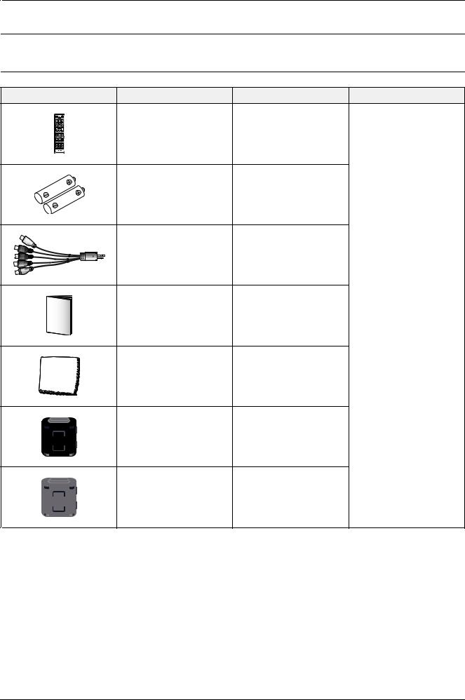
2.5. Accessories
2.5.1.Supplied Accessories
Accessories |
Item |
Item code |
Remark |
|
Remote Control |
AA59-00445A |
|
|
Batteries |
4301-000103 |
|
|
CBF Signal |
BN39-01154F |
|
|
Owner`s Instructions |
BN68-03421A |
Samsung Service Center |
|
Cleaning Cloth |
BN63-01798B |
|
|
Ferrite Core |
3301-002053 |
|
|
(2EA) |
|
|
|
|
|
|
|
Ferrite Core |
3301-002052 |
|
|
(1EA) |
|
|
|
|
|
2-6 |
Copyright© 1995-2011 SAMSUNG. All rights reserved. |
2. Product Specification
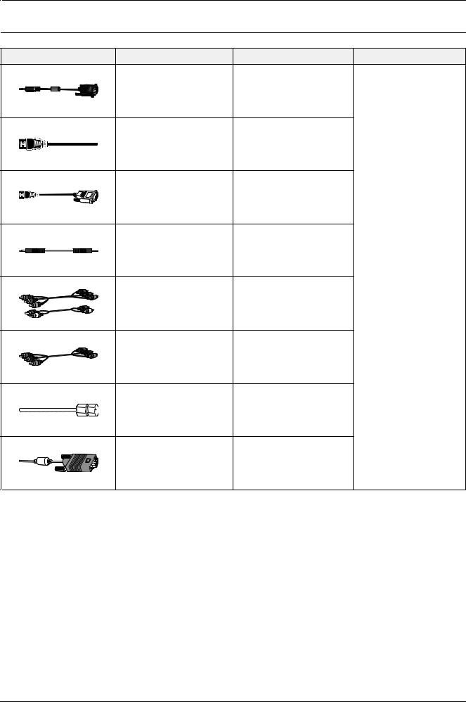
2.5.2.Sold Separately
Accessories |
Item |
Item code |
Remark |
|
RS232 Cable |
- |
|
|
HDMI |
- |
|
|
HDMI-DVI |
- |
|
|
Audio |
- |
|
|
|
|
Samsung Service Center |
|
Component |
- |
|
|
Composite (AV) |
- |
|
|
Coaxial (RF) |
- |
|
|
VGA |
- |
|
Copyright© 1995-2011 SAMSUNG. All rights reserved. |
2-7 |
3. Disassembly & Reassembly
3. Disassembly & Reassembly
3.1. Overall Disassembly & Reassembly
 CAUTION
•Be sure to separate the power cord before disassembling the unit.
•Discharge the capacitors first when separating PCB’s with high capacity capacitors such as SMPS, X Main Board, Y Main Board, etc. (A spark may be generated by the electric charge, and there is danger of electronic shock.)
•Check that the cables are properly connected referring to the circuit diagram when disassembling or assembling the unit taking care not to damage the cables
•Take care not to scratch the Glass Filter in the front.
•Assemble the boards in the reverse order of the disassembly.
•The plasma must be layed down on a flat padded surface for disassembly and reassembly.
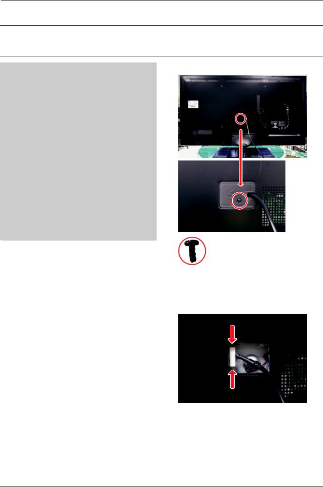
1. Remove a screw of Inlet Cover.
6003–000337 : M4 * L10
2.Remove the Inlet Cover.
3.Push both side and pull the cord down to remove it from the unit.
4. Place monitor face down on cushioned table.
Copyright© 1995-2011 SAMSUNG. All rights reserved. |
3-1 |
3. Disassembly & Reassembly
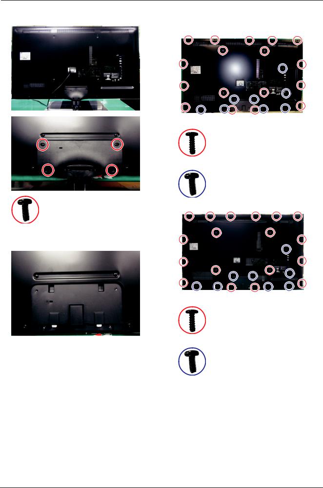
5. Remove screws from the Stand. |
7. Remove the screws of Rear-Cover. |
|
* "6003-001782" Screw – 51" : 17ea, 59"/64" : 18ea |
<51" PDP>
6003–001782 : M4 * L12
6003–000337 : M4 * L10
6003–000337 : M4 * L10
6. Remove Stand.
<59" / 64" PDP>
6003–001782 : M4 * L12
6003–000337 : M4 * L10
3-2 |
Copyright© 1995-2011 SAMSUNG. All rights reserved. |

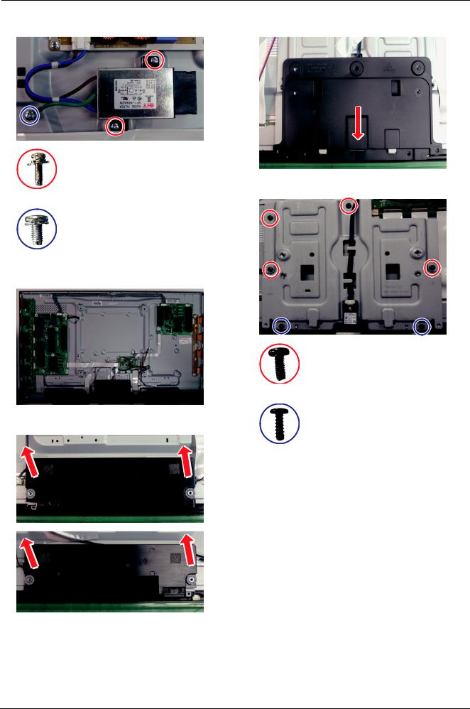
3. Disassembly & Reassembly
8. Lift up and remove the Rear-Cover. |
11. Remove the screws of SMPS. |
 CAUTION
Disconnect all cabling from the boards prior to removing.
9. Remove the screws of Main Board.
 CAUTION
When you remove Boards, you must disconnect all
connectors. If you don't, it can cause problems.
<51" SMPS>
6001–002606 : M3 * L10
<59" / 64" SMPS>
6001–002606 : M3 * L10
6001–002606 : M3 * L10
10. Remove the LVDS Cable
12. Remove the SMPS.
(1) Pull the cover plate.
(2) Draw a cable with pushing the both side.
1
2
Copyright© 1995-2011 SAMSUNG. All rights reserved. |
3-3 |
3. Disassembly & Reassembly
13. Remove the screws of AC-Inlet. |
16. Pull the Cover Bottom in the direction shown. |
17. Remove Screws of the Bracket Stand-Link.
6001–002606 : M3 * L10
6003–001439 : M4 * L8
14. Remove AC-Innet.
6003–000337 : M4 * L10
15. Remove the speakers. (R/L)
6003–001782 : M4 * L12
3-4 |
Copyright© 1995-2011 SAMSUNG. All rights reserved. |
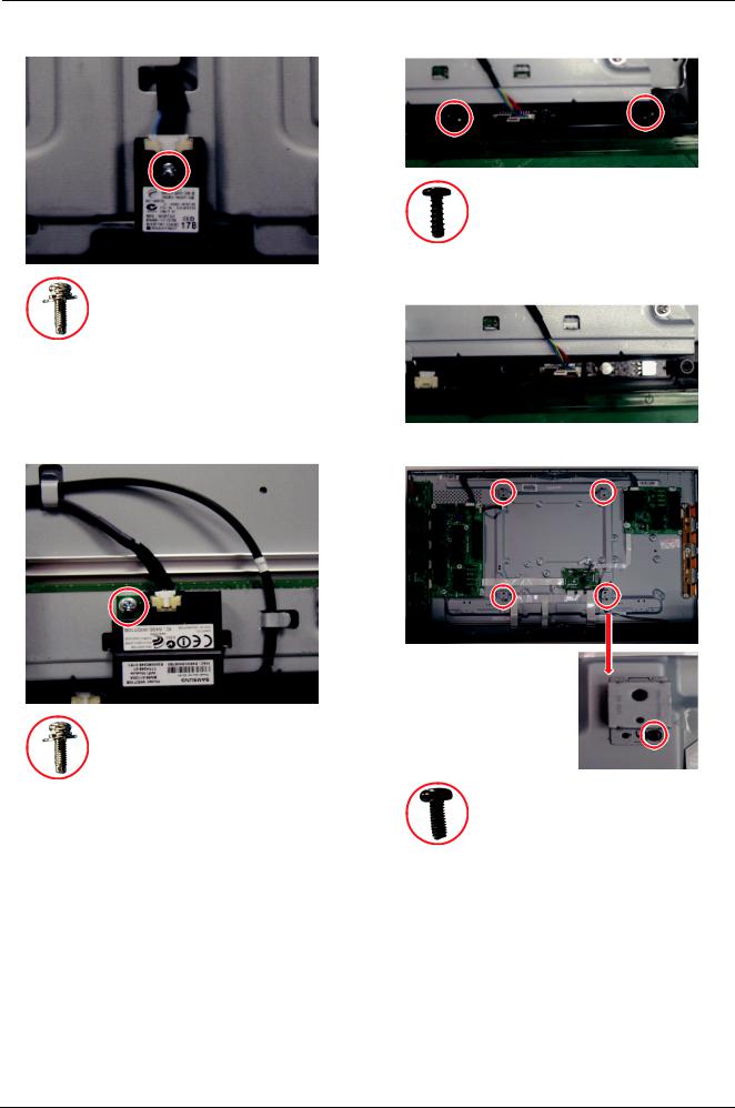
3. Disassembly & Reassembly
18. Remove the screw of the Bluetooth.
6001–002606 : M3 * L10
19.Remove the Bluetooth.
20.Remove the Bracket Stand-Link.
21.Remove the screw of Wi-Fi.
6001–002606 : M3 * L10
22. Remove the Wi-Fi.
23. Remove screws of the Function Holder.
6003–001782 : M4 * L12
24. Remove the Function Holder.
25. Remove screws of the Bracket Wall.
6003–000337 : M4 * L10
26. Remove the Bracket Wall.
Copyright© 1995-2011 SAMSUNG. All rights reserved. |
3-5 |
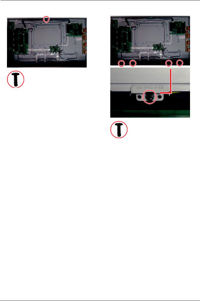
3. Disassembly & Reassembly
27. Remove the screws of the Front Cover.
6003–001782 : M4 * L12
28. Remove 4 screws of the Bracket-Module.
6003–001782 : M4 * L12
29.Remove the Bracket-Module.
*Then Module is separated.
3-6 |
Copyright© 1995-2011 SAMSUNG. All rights reserved. |

4. Troubleshooting
4. Troubleshooting
4.1. Checkpoints by Error Mode
4.1.1.First Checklist for Troubleshooting
1)Check the various cable connections first.
•Check to see if there is a burnt or damaged cable.
•Check to see if there is a disconnected or loose cable connection.
•Check to see if the cables are connected according to the connection diagram.
2)Check the power input to the Main Board.
3)How to distinguish if the problem is caused by Main board or Logic Board.
•No Video : If the problem is No Video but Logic Board is on and Indication LED is blinking repeatedly and faster than normal booting, replace the T-Con board.
•Distorted Picture : Check the inner patterns.
Inner pattern |
Picture |
Problem |
OK |
NG |
Main board |
|
|
|
NG |
NG |
Main or LVDS cable or Logic Board or Panel. |
|
|
|
•How to check inner pattern?
a.Entering Factory mode.
b.Move to SVC menu.
c.Move to Test Pattern.
d.Check inner patterns.
Copyright© 1995-2011 SAMSUNG. All rights reserved. |
4-1 |
Loading...