


 Loading...
PLASMA DISPLAY TV
Chassis: F65A(P_HD)_B430
Model : PS42B430P2WXXH
SERVICE Manual
PLASMA DISPLAY TV |
|
|
CONTENTS |
1. |
Precaution |
||
2. |
Product Specification |
||
3. |
Disassembly & Reassembly |
||
4. |
Troubleshooting |
||
5. |
Exploded View & Part List |
||
6. |
Wiring Diagram |
||
PS42B430P2W
Refer to the service manual in the GSPN (see the rear cover) for the more information.

GSPN (Global Service Partner Network)
Area |
Web Site |
North America |
service.samsungportal.com |
|
|
Latin America |
latin.samsungportal.com |
|
|
CIS |
cis.samsungportal.com |
|
|
Europe |
europe.samsungportal.com |
|
|
China |
china.samsungportal.com |
|
|
Asia |
asia.samsungportal.com |
|
|
Mideast & Africa |
mea.samsungportal.com |
|
|
This Service Manual is a property of Samsung Electronics Co.,Ltd. Any unauthorized use of Manual can be punished under applicable International and/or domestic law.
©Samsung Electronics Co., Ltd. Apr. 2009 Printed in Korea
AA82-05791A

Table of Contents
Chapter 1 Precaution
■ 1-1 Safety Precautions . . . . . . . . . . . . . . . . . . . . . . . . . . . . . . . . . . . . . . . . . . . . . . . . . . . . . . . . . . . 1-1 ■ 1-2 Servicing Precautions . . . . . . . . . . . . . . . . . . . . . . . . . . . . . . . . . . . . . . . . . . . . . . . . . . . . . . . . 1-3 ■ 1-3 Static Electricity Precautions . . . . . . . . . . . . . . . . . . . . . . . . . . . . . . . . . . . . . . . . . . . . . . . . . . . 1-4 ■ 1-4 Installation Precautions . . . . . . . . . . . . . . . . . . . . . . . . . . . . . . . . . . . . . . . . . . . . . . . . . . . . . . . 1-5
Chapter 2 Product Specification
■ 2-1 Product Specification . . . . . . . . . . . . . . . . . . . . . . . . . . . . . . . . . . . . . . . . . . . . . . . . . . . . . . . . . 2-1
■ 2-2 Specifications Analysis . . . . . . . . . . . . . . . . . . . . . . . . . . . . . . . . . . . . . . . . . . . . . . . . . . . . . . . . 2-3
■ 2-3 Accessories . . . . . . . . . . . . . . . . . . . . . . . . . . . . . . . . . . . . . . . . . . . . . . . . . . . . . . . . . . . . . . . . 2-4
Chapter 3 Disassembly & Reassembly
■ 3-1 Overall Disassembly & Reassembly . . . . . . . . . . . . . . . . . . . . . . . . . . . . . . . . . . . . . . . . . . . . . |
3-1 |
Chapter 4 Troubleshooting
■ 4-1 Troubleshooting . . . . . . . . . . . . . . . . . . . . . . . . . . . . . . . . . . . . . . . . . . . . . . . . . . . . . . . . . . . . . 4-1
■ 4-2 Adjustment . . . . . . . . . . . . . . . . . . . . . . . . . . . . . . . . . . . . . . . . . . . . . . . . . . . . . . . . . . . . . . . . . 4-14
■ 4-3 Upgrade . . . . . . . . . . . . . . . . . . . . . . . . . . . . . . . . . . . . . . . . . . . . . . . . . . . . . . . . . . . . . . . . . . . 4-32
Chapter 5 Exploded View & Part List
■ 5-1 PS42B430P2WXXH Exploded View . . . . . . . . . . . . . . . . . . . . . . . . . . . . . . . . . . . . . . . . . . . . . 5-1 ■ 5-2 PS42B430P2WXXH Service Item . . . . . . . . . . . . . . . . . . . . . . . . . . . . . . . . . . . . . . . . . . . . . . . 5-5
Chapter 6 Wiring Diagram
■ 6-1 Overall Wiring . . . . . . . . . . . . . . . . . . . . . . . . . . . . . . . . . . . . . . . . . . . . . . . . . . . . . . . . . . . . . . . 6-1
Precaution
1. Precaution
To avoid possible damage, electric shocks or exposure to radiation, follow the instructions below with regard to safety, installation, service and ESD.
1-1 Safety Precautions
1.Make sure all protective devices are properly installed including non-metallic handles and compartment covers when installing or re-installing the chassis or chassis assemblies.
2.Make sure there aren't any gaps between the front and rear cover that anyone could insert they're fingers into and receive any electrical shock. These gaps include ventilation holes, cracks, etc.
Errors may occur when the resistance is below 1.0 or
over 5.2 . In these cases, make sure that the device is repaired before sending it back to the customer.
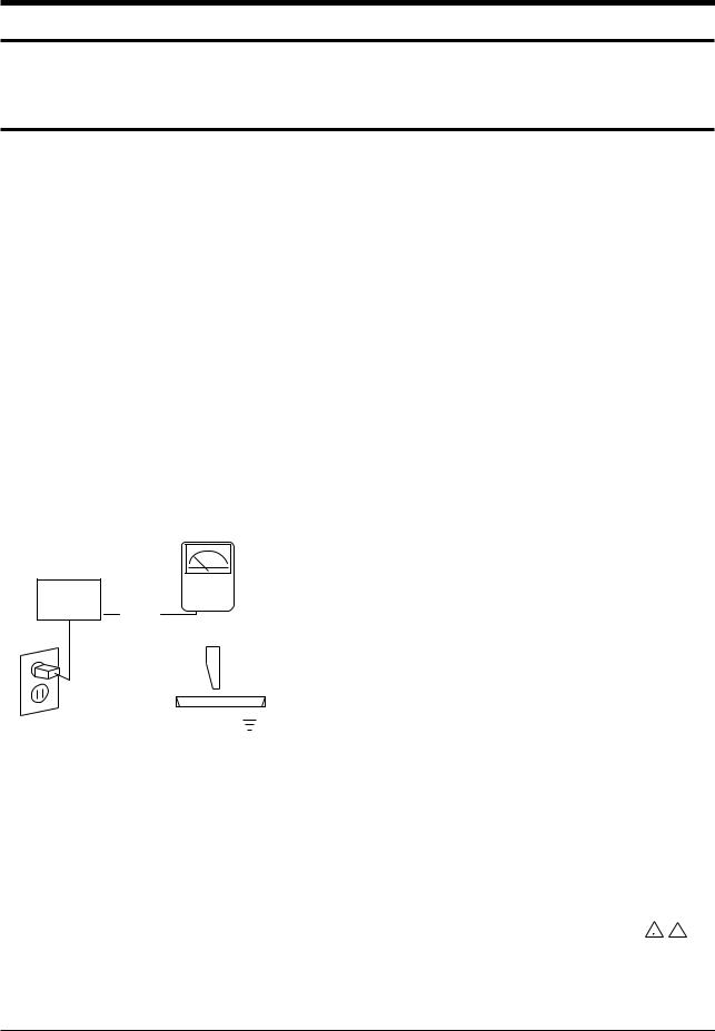
3.Check for Electricity Leakage (Figure 1-1) Warning: Do not use an insulated transformer for
checking the leakage. Use only those current leakage testers or mirroring systems that comply with ANSIC 101.1 and the Underwriter Laboratory's specifications (UL1410, 59.7).
Fig. 1-1 AC Leakage Test
|
|
|
|
|
(READING SHOULD |
||
DEVICE |
LEAKAGE |
NOT BE ABOVE |
|||||
CURRENT |
|
|
0.5mA) |
||||
UNDER |
TESTER |
|
|
|
|||
TEST |
|
|
|
|
|
|
|
|
TEST ALL |
|
|
|
|
|
|
EXPOSED METAL |
|
|
|
|
|
||
SURFACES |
|
|
|
|
|
||
2-WIRE CORD |
|
|
|
|
|
||
ALSO TEST WITH |
|
|
|
|
|
||
PLUG REVERSED |
|
|
|
|
|
||
(USING AC ADAPTER |
|
|
|
|
EARTH |
||
PLUG AS REQUIRED) |
|
|
|
GROUND |
|||
|
|
|
|
|
|
|
|
4.A high voltage is maintained within the specified limits using safety parts, calibration and tolerances. When voltage exceeds the specified limits, check each special part.
5.Warning for Engineering Changes:
Never make any changes or additions to the circuit design or the internal part for this product.
Ex: Do not add any audio or video accessory connectors. This might cause physical damage. Furthermore, any changes or additions to the original design/engineering will invalidate the warranty.
6.Warning - Hot Chassis:
Some TV chassis are directly connected to one end of the AC power cord for electrical reasons. Without insulated transformers, the product can only be repaired safely when the chassis is connected to the earth end of the AC power source.
To make sure the AC power cord is properly connected, follow the instructions below. Use the voltmeter to measure the voltage between the chassis and the earth ground. If the measurement is over 1.0V, unplug the AC power cord and change the polarity before re-inserting it. Measure the voltage between the chassis and the ground again.
7.Some TV chassis are shipped with an additional secondary grounding system. The secondary system is adjacent to the AC power line. These two grounding systems are separated in the circuit using an unbreakable/unchangeable insulation material.
8.When any parts, material or wiring appear overheated or damaged, replace them with new immediately. When any damage or overheating is detected, correct this immediately and make a regular check of possible errors.
9.Check for the original shape of the lead, especially that of the antenna wiring, any sharp edges, the AC power and the high voltage power. Carefully check if the wiring is too tight, incorrectly placed or loose. Never change the space between the part and the printed circuit board. Check the AC power cord for possible damages.
Keep the part or the lead away from any heat-emitting materials.
10.Safety Indication:
Some electrical circuits or device related materials require special attention to their safety features, which cannot be viewed by the naked eye. If an original part is replaced with another irregular one, the safety or protective features will be lost even if the new one has a higher voltage or more watts.
Critical safety parts should be marked with (  ! ). Use only regular parts for replacements (in particular, flame resistance and dielectric strength specifications). Irregular parts or materials may cause electric shock or fire.
Samsung Electronics |
1-1 |

Precaution
1-2 Servicing Precautions
Warning 1: First carefully read the "Safety Instruction" in this service manual. When there is a conflict between the service and the safety instructions, follow the safety instruction at all times.
Warning 2: Any electrolytic capacitor with the wrong polarity will explode.
1.The service instructions are printed on the cabinet, and should be followed by any service personnel.
(UL / FCC ¡æ Refer to the Back Cabinet )
2.Make sure to unplug the AC power cord from the power source before starting any repairs.
(a)Remove or re-install parts or assemblies.
(b)Disconnect the electric plug or connector, if any.
(c)Connect the test part in parallel with the electrolytic capacitor.
3.Some parts are placed at a higher position than the printed board. Insulated tubes or tapes are used for this purpose. The internal wiring is clamped using buckles to avoid contact with heat emitting parts. These parts should be installed back to their original position.
4.After the repair, make sure to check if the screws, parts or cables are properly installed. Make sure no damage is caused to the repaired part and its surroundings.
5.Check for insulation between the blade of the AC plug and that of any conductive materials (i.e. the metal panel, input terminal, earphone jack, etc).
6.Insulation Check Process: Unplug the power cord from the AC source and turn the switch on. Connect the insulating resistance meter (500v) to the AC plug blade.
The insulating resistance between the blade of the AC plug and that of the conductive material should be more than 1 .
7.Any B+ interlock should not be damaged.
If the metal heat sink is not properly installed, no connection to the AC power should be made.
8.Make sure the grounding lead of the tester is connected to the chassis ground before connecting to the positive lead. The ground lead of the tester should be removed last.
9.Beware of risks of any current leakage coming into contact with the high-capacity capacitor.
10.The sharp edges of the metal material may cause physical damage, so protect yourself by wearing gloves during the repair.
11.Due to the nature of plasma display panels, partial afterimages may appear if a still picture is displayed on the screen for a long period of time. This is caused by brightness deterioration due to the storage effect of the panel, and to prevent this from happening, we recommend that the brightness and contrast are reduced.
(e.g.) Contrast: 25, Brightness: 50
1-2 |
Samsung Electronics |

Precaution
1-3 Static Electricity Precautions
1.Some semi-conductive ("solid state") devices are vulnerable to static electricity. These devices are known as ESD. ESD includes the integrated circuit and the field effect transistor. To avoid any materials damage from electrostatic shock, follow the instructions described below.
2.Remove any static electricity from your body by connecting the earth ground before handling any semi-conductive parts or assemblies. Alternatively, wear a dischargeable wrist-belt. (Make sure to remove any static electricity before connecting the power source - this is a safety instruction for avoiding electric shock)
3.Remove the ESD assembly and place it on a conductive surface such as aluminum foil to prevent accumulating static electricity.
4.Do not use any Freon-based chemicals. Such chemicals will generate static electricity that causes damage to the ESD.
5.Use only grounded-tip irons for soldering purposes.
6.Use only anti-static solder removal devices. Most solder removal devices do not support an anti-static feature.
A solder removal device without an anti-static feature can store enough static electricity to cause damage to the ESD.
7.Do not remove the ESD from the protective box until the replacement is ready. Most ESD replacements are covered with lead, which will cause a short to the entire unit due to the conductive foam, aluminum foil or other conductive materials.
8.Remove the protective material from the ESD replacement lead immediately after connecting it to the chassis or circuit assembly.
9.Take extreme caution in handling any uncovered ESD replacements. Actions such as brushing clothes or lifting your leg from the carpet floor can generate enough static electricity to damage the ESD.
CAUTION
These servicing instructions are for use by qualified service personnel only.
To reduce the risk of electric shock do not perform any servicing other than that contained in the operating instructions unless you are qualified to do so.
Samsung Electronics |
1-3 |

Precaution
1-4 Installation Precautions
1.For safety reasons, more than two people are required for carrying the product.
2.Keep the power cord away from any heat emitting devices, as a melted covering may cause fire or electric shock.
3.Do not place the product in areas with poor ventilation such as a bookshelf or closet. The increased internal temperature may cause fire.
4.Bend the external antenna cable when connecting it to the product. This is a measure to protect it from being exposed to moisture. Otherwise, it may cause a fire or electric shock.
5.Make sure to turn the power off and unplug the power cord from the outlet before repositioning the product. Also check the antenna cable or the external connectors if they are fully unplugged. Damage to the cord may cause fire or electric shock.
6.Keep the antenna far away from any high-voltage cables and install it firmly. Contact with the high-voltage cable or the antenna falling over may cause fire or electric shock.
7.When connecting the RF antenna, check for a DTV receiving system and install a separate DTV reception antenna for areas with no DTV signal.
8.When installing the product, leave enough space (4") between the product and the wall for ventilation purposes. A rise in temperature within the product may cause fire.
9.When moving a PDP with removable speakers, detach the speakers first before moving the main body. Moving the PDP main body without separating the speakers may cause the speakers to detach, possibly causing damage or injury.
1-4 |
Samsung Electronics |

Disassembly & Reassembly
3. Disassembly & Reassembly
3-1 Overall Disassembly & Reassembly
!Notice
-Be sure to separate the power cord before disassembling the unit.
-Discharge the capacitors first when separating PCB's with high capacity capacitors such as SMPS, X Main Board, Y Main Board, etc. (A spark may be generated by the electric charge, and there is danger of electronic shock.)
-Check that the cables are properly connected referring to the circuit diagram when disassembling or assembling the unit taking care not to damage the cables.
-Take care not to scratch the Glass Filter in the front.
-Assemble the boards in the reverse order of the disassembly.
-The plasma must be layed down on a flat padded surface for disassembly and reassembly.
3-1-1 Separation of ASSY COVER P-REAR
Part Name |
Description |
Description Photo |
Cover |
Remove 17 screws. ( |
) |
Rear |
: BH,+,B,M4,L3,ZPC(BLK) |
|
|
Remove 6 screws. ( ) |
|
|
: PH,+,WSP,S,M4,L35,ZPC(BLK) |
|
Remove the rear cover.
! : Please lay the PDP unit face down on a soft surface when removing the stand.
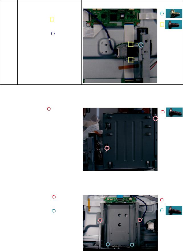
3-1-2 Separation of ASSY PCB MISC-MAIN
Part Name |
Description |
Description Photo |
|||
Main |
Detach all connectors from the Main |
|
|
|
|
|
|
|
|
||
Board |
Board. |
|
|
|
|
|
Remove 4 screws. |
|
|
|
|
|
|
|
|
|
|
|
: PH,+,WWP,M3,L8,NI PLT |
|
|
|
|
|
Remove the Main Board. |
|
|
|
|
|
|
|
|
|
|
|
|
|
|
|
|
Samsung Electronics |
3-1 |
Disassembly & Reassembly
3-1-3 Separation of FILTER-EMI AC LINE
Part Name |
Description |
Description Photo |
||||
FILTER- |
Detach connector from SMPS. |
|
|
|
|
|
|
|
|
|
|||
EMI |
|
|
|
|
|
|
AC LINE |
Remove 2 screw. ( |
) |
|
|
|
|
|
|
|
|
|||
|
: PH,+,WWP,M3,L8,NI PLT |
|
|
|
|
|
|
Remove 1 screws.( |
) |
|
|
|
|
|
|
|
|
|
||
|
: BH,+,S,M4,L10,ZPC(BLK) |
|
|
|
|
|
Separate FILTER-EMI AC LINE from bracket.
3-1-4 Separation of BRACKET-PCB
Part Name |
Description |
Description Photo |
||
Bracket |
Remove screw.( ) |
|
|
|
|
|
|
||
PCB |
: BH,+,B,M4,L3,ZPC(BLK) |
|
|
|
|
Remove the BRACKET-PCB. |
|
|
|
|
|
|
|
|
|
|
|
|
|
3-1-5 Separation of ASSY BRACKET
Part Name |
Description |
Description Photo |
|||
Bracket |
Remove 2 screws. ( |
) |
|
|
|
|
|
|
|||
|
: BH,+,PT,S Tite,M4,L10,ZPC(BLK) |
|
|
|
|
|
Remove 2 screws. ( |
) |
|
|
|
|
|
|
|
||
|
|
|
|
||
|
: BH,+,B,M4,L3,ZPC(BLK) |
|
|
|
|
|
|
|
|
||
|
Remove Bracket. |
|
|
|
|
|
|
|
|
|
|
|
|
|
|
|
|
3-2 |
Samsung Electronics |

Disassembly & Reassembly
3-1-6 Separation of ASSY BRACKET P-WALL
Part Name |
Description |
Description Photo |
|||
Wall |
Remove 2 screws. ( ) |
|
|
|
|
Bracket |
: BH,+,B,M4,L3,ZPC(BLK) |
|
|
|
|
|
|
|
|
|
|
Remove 4 screws. (
 )
)
: BH,+,S,M4,L10,ZPC(BLK)
Remove Wall Bracket.
! : Please lay the PDP panel face down on a soft surface when separating front cover.
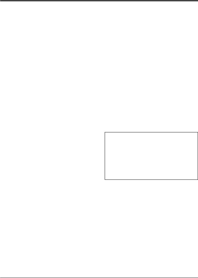
3-1-7 Separation of ASSY SPEAKER P
Part Name |
Description |
Description Photo |
|||
Speaker |
Remove 4 screws.( ) |
|
|
|
|
|
|
|
|
||
|
: BH,+,WP,B,M4.0,L3,ZPC(BLK), |
|
|
|
|
|
SWRCH18A |
|
|
|
|
|
|
|
|
|
|
|
Remove the Speaker. |
|
|
|
|
|
|
|
|
|
|
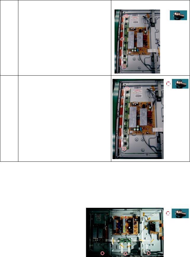
3-1-8 Separation of SMPS-PDP TV
Part Name |
|
|
Description |
Description Photo |
|||
SMPS |
Detach all connectors from the SMPS. |
|
|
|
|
||
|
|
|
|
||||
|
Remove 6 screws. |
|
|
|
|
||
|
|
|
|
|
|||
|
|
|
: PH,+,WWP,M3,L8,NI PLT |
|
|
|
|
|
Remove the SMPS. |
|
|
|
|
||
|
|
|
: Wear gloves when handling the power |
|
|
|
|
|
|
! |
|
|
|
|
|
|
|
|
board as there may be some remaining |
|
|
|
|
|
|
|
electrical charge in the capacitor. |
|
|
|
|
|
|
|
Specifically, avoid touching any part of |
|
|
|
|
|
|
|
the capacitor. |
|
|
|
|
|
|
|
|
|
|
|
|
Samsung Electronics |
3-3 |
Disassembly & Reassembly
3-1-9 Separation of ASSY PDP MODULE P-LOGIC MAIN BOARD
Part Name |
Description |
Description Photo |
|||
Logic |
Detach all connectors from the Logic |
|
|
|
|
|
|
|
|
||
Board |
Main Board. |
|
|
|
|
|
Remove 2 screws. |
|
|
|
|
|
|
|
|
|
|
|
: WSP,PH,+,M3,L8,NI PLT |
|
|
|
|
|
Remove the Logic Main Board. |
|
|
|
|
|
|
|
|
|
|
3-4 |
Samsung Electronics |

Disassembly & Reassembly
3-1-10 Separation of ASSY PDP MODULE P-X MAIN BOARD
Part Name |
|
Description |
Description Photo |
||
Flat able |
Detach all Connectors from the X Main Board. |
|
|
|
|
|
To separate the Flat Cable of the X-Board, press the |
|
|
|
|
|
|
upper and the lower sides of the connector. |
|
|
|
|
|
: Pinch the sides, but then push down in the ribbon, it |
|
|
|
|
! |
|
|
|
|
|
|
should slide out after that. |
|
|
|
|
|
|
|
|
|
X-Main |
Remove 7 screws. |
|
|
|
|
||
Board |
: PH,+,WWP,M3,L8,NI PLT |
|
|
|
Remove the X-Main Board. |
|
|
|
|
|
X-Main Remove the X-Main Board.
Board
Samsung Electronics |
3-5 |
Disassembly & Reassembly
3-1-11 Separation of ASSY PDP MODULE P-Y MAIN BOARD
Part Name |
Description |
|
Description Photo |
||||||
Flat Cable |
Detach the scan board connectors from the panel . |
|
|
|
|
|
|
|
|
|
|
|
|
|
|
|
|
||
|
|
|
|
|
|
|
|
||
|
|
|
|
|
|
|
|
|
|
|
|
|
|
|
|
|
|
|
|
|
|
|
|
|
|
|
|
|
|
Y-Scan |
Remove 2 screws. |
|
|
Board |
: PH,+,WWP,M3,L8,NI PLT |
|
|
|
|
|
|
3-1-12 Separation of ASSY PDP MODULE P-ADDRESS BUFFER BOARD
Part Name |
Description |
Description Photo |
|||
Buffer |
Remove 3 screws. |
|
|
|
|
|
|
|
|
||
board |
: PH,+,WWP,M3,L8,NI PLT |
|
|
|
|
shield |
Remove the still bar. |
|
|
|
|
|
|
|
|
||
|
|
|
|
|
|
|
Before removing the still bar, you should |
|
|
|
|
|
lift up the panel a little. |
|
|
|
|
|
|
|
|
|
|
|
|
|
|
|
|
3-6 |
Samsung Electronics |

Disassembly & Reassembly
3-1-13 Separation of ASSY PANEL BRACKETS
Part Name |
Description |
Description Photo |
|||
Panel |
Remove 7 screws. ( ) |
|
|
|
|
|
|
|
|
||
Brackets |
: BH,+,B,M4,L3,ZPC(BLK) |
|
|
|
|
|
Remove the Side Panel Brackets. |
|
|
|
|
|
|
|
|
|
|
|
|
|
|
|
|
Samsung Electronics |
3-7 |

MEMO
3-8 |
Samsung Electronics |

Precaution
1. Precaution
To avoid possible damage, electric shocks or exposure to radiation, follow the instructions below with regard to safety, installation, service and ESD.
1-1 Safety Precautions
1.Make sure all protective devices are properly installed including non-metallic handles and compartment covers when installing or re-installing the chassis or chassis assemblies.
2.Make sure there aren't any gaps between the front and rear cover that anyone could insert they're fingers into and receive any electrical shock. These gaps include ventilation holes, cracks, etc.
Errors may occur when the resistance is below 1.0 or
over 5.2 . In these cases, make sure that the device is repaired before sending it back to the customer.
3.Check for Electricity Leakage (Figure 1-1) Warning: Do not use an insulated transformer for
checking the leakage. Use only those current leakage testers or mirroring systems that comply with ANSIC 101.1 and the Underwriter Laboratory's specifications (UL1410, 59.7).
Fig. 1-1 AC Leakage Test
|
|
|
|
|
(READING SHOULD |
||
DEVICE |
LEAKAGE |
NOT BE ABOVE |
|||||
CURRENT |
|
|
0.5mA) |
||||
UNDER |
TESTER |
|
|
|
|||
TEST |
|
|
|
|
|
|
|
|
TEST ALL |
|
|
|
|
|
|
EXPOSED METAL |
|
|
|
|
|
||
SURFACES |
|
|
|
|
|
||
2-WIRE CORD |
|
|
|
|
|
||
ALSO TEST WITH |
|
|
|
|
|
||
PLUG REVERSED |
|
|
|
|
|
||
(USING AC ADAPTER |
|
|
|
|
EARTH |
||
PLUG AS REQUIRED) |
|
|
|
GROUND |
|||
|
|
|
|
|
|
|
|
4.A high voltage is maintained within the specified limits using safety parts, calibration and tolerances. When voltage exceeds the specified limits, check each special part.
5.Warning for Engineering Changes:
Never make any changes or additions to the circuit design or the internal part for this product.
Ex: Do not add any audio or video accessory connectors. This might cause physical damage. Furthermore, any changes or additions to the original design/engineering will invalidate the warranty.
6.Warning - Hot Chassis:
Some TV chassis are directly connected to one end of the AC power cord for electrical reasons. Without insulated transformers, the product can only be repaired safely when the chassis is connected to the earth end of the AC power source.
To make sure the AC power cord is properly connected, follow the instructions below. Use the voltmeter to measure the voltage between the chassis and the earth ground. If the measurement is over 1.0V, unplug the AC power cord and change the polarity before re-inserting it. Measure the voltage between the chassis and the ground again.
7.Some TV chassis are shipped with an additional secondary grounding system. The secondary system is adjacent to the AC power line. These two grounding systems are separated in the circuit using an unbreakable/unchangeable insulation material.
8.When any parts, material or wiring appear overheated or damaged, replace them with new immediately. When any damage or overheating is detected, correct this immediately and make a regular check of possible errors.
9.Check for the original shape of the lead, especially that of the antenna wiring, any sharp edges, the AC power and the high voltage power. Carefully check if the wiring is too tight, incorrectly placed or loose. Never change the space between the part and the printed circuit board. Check the AC power cord for possible damages.
Keep the part or the lead away from any heat-emitting materials.
10.Safety Indication:
Some electrical circuits or device related materials require special attention to their safety features, which cannot be viewed by the naked eye. If an original part is replaced with another irregular one, the safety or protective features will be lost even if the new one has a higher voltage or more watts.
Critical safety parts should be marked with (  ! ). Use only regular parts for replacements (in particular, flame resistance and dielectric strength specifications). Irregular parts or materials may cause electric shock or fire.
Samsung Electronics |
1-1 |

Precaution
1-2 Servicing Precautions
Warning 1: First carefully read the "Safety Instruction" in this service manual. When there is a conflict between the service and the safety instructions, follow the safety instruction at all times.
Warning 2: Any electrolytic capacitor with the wrong polarity will explode.
1.The service instructions are printed on the cabinet, and should be followed by any service personnel.
(UL / FCC ¡æ Refer to the Back Cabinet )
2.Make sure to unplug the AC power cord from the power source before starting any repairs.
(a)Remove or re-install parts or assemblies.
(b)Disconnect the electric plug or connector, if any.
(c)Connect the test part in parallel with the electrolytic capacitor.
3.Some parts are placed at a higher position than the printed board. Insulated tubes or tapes are used for this purpose. The internal wiring is clamped using buckles to avoid contact with heat emitting parts. These parts should be installed back to their original position.
4.After the repair, make sure to check if the screws, parts or cables are properly installed. Make sure no damage is caused to the repaired part and its surroundings.
5.Check for insulation between the blade of the AC plug and that of any conductive materials (i.e. the metal panel, input terminal, earphone jack, etc).
6.Insulation Check Process: Unplug the power cord from the AC source and turn the switch on. Connect the insulating resistance meter (500v) to the AC plug blade.
The insulating resistance between the blade of the AC plug and that of the conductive material should be more than 1 .
7.Any B+ interlock should not be damaged.
If the metal heat sink is not properly installed, no connection to the AC power should be made.
8.Make sure the grounding lead of the tester is connected to the chassis ground before connecting to the positive lead. The ground lead of the tester should be removed last.
9.Beware of risks of any current leakage coming into contact with the high-capacity capacitor.
10.The sharp edges of the metal material may cause physical damage, so protect yourself by wearing gloves during the repair.
11.Due to the nature of plasma display panels, partial afterimages may appear if a still picture is displayed on the screen for a long period of time. This is caused by brightness deterioration due to the storage effect of the panel, and to prevent this from happening, we recommend that the brightness and contrast are reduced.
(e.g.) Contrast: 25, Brightness: 50
1-2 |
Samsung Electronics |
Precaution
1-3 Static Electricity Precautions
1.Some semi-conductive ("solid state") devices are vulnerable to static electricity. These devices are known as ESD. ESD includes the integrated circuit and the field effect transistor. To avoid any materials damage from electrostatic shock, follow the instructions described below.
2.Remove any static electricity from your body by connecting the earth ground before handling any semi-conductive parts or assemblies. Alternatively, wear a dischargeable wrist-belt. (Make sure to remove any static electricity before connecting the power source - this is a safety instruction for avoiding electric shock)
3.Remove the ESD assembly and place it on a conductive surface such as aluminum foil to prevent accumulating static electricity.
4.Do not use any Freon-based chemicals. Such chemicals will generate static electricity that causes damage to the ESD.
5.Use only grounded-tip irons for soldering purposes.
6.Use only anti-static solder removal devices. Most solder removal devices do not support an anti-static feature.
A solder removal device without an anti-static feature can store enough static electricity to cause damage to the ESD.
7.Do not remove the ESD from the protective box until the replacement is ready. Most ESD replacements are covered with lead, which will cause a short to the entire unit due to the conductive foam, aluminum foil or other conductive materials.
8.Remove the protective material from the ESD replacement lead immediately after connecting it to the chassis or circuit assembly.
9.Take extreme caution in handling any uncovered ESD replacements. Actions such as brushing clothes or lifting your leg from the carpet floor can generate enough static electricity to damage the ESD.
CAUTION
These servicing instructions are for use by qualified service personnel only.
To reduce the risk of electric shock do not perform any servicing other than that contained in the operating instructions unless you are qualified to do so.
Samsung Electronics |
1-3 |

Precaution
1-4 Installation Precautions
1.For safety reasons, more than two people are required for carrying the product.
2.Keep the power cord away from any heat emitting devices, as a melted covering may cause fire or electric shock.
3.Do not place the product in areas with poor ventilation such as a bookshelf or closet. The increased internal temperature may cause fire.
4.Bend the external antenna cable when connecting it to the product. This is a measure to protect it from being exposed to moisture. Otherwise, it may cause a fire or electric shock.
5.Make sure to turn the power off and unplug the power cord from the outlet before repositioning the product. Also check the antenna cable or the external connectors if they are fully unplugged. Damage to the cord may cause fire or electric shock.
6.Keep the antenna far away from any high-voltage cables and install it firmly. Contact with the high-voltage cable or the antenna falling over may cause fire or electric shock.
7.When connecting the RF antenna, check for a DTV receiving system and install a separate DTV reception antenna for areas with no DTV signal.
8.When installing the product, leave enough space (4") between the product and the wall for ventilation purposes. A rise in temperature within the product may cause fire.
9.When moving a PDP with removable speakers, detach the speakers first before moving the main body. Moving the PDP main body without separating the speakers may cause the speakers to detach, possibly causing damage or injury.
1-4 |
Samsung Electronics |

Product Specification
2. Product Specification
2-1 Product Specification
Features
Block |
Specification |
|
Major IC |
|
Remark |
|
RF |
Digital/Analog (DTV Built In) |
|
Tuner |
|
|
|
|
DNOQ403SH151A |
SAMSUNG |
|
|||
|
|
|
|
|||
PDP Module |
Samsung SDI U1P Module |
|
42"HD |
|
New Module |
|
Power |
Samsung/Dong-yang electro |
|
|
|
|
|
mechanics SMPS |
|
|
|
|
||
|
|
|
|
|
||
Video |
NTSC 3.58, ATSC |
|
SEMS12 |
|
|
|
HDMI |
|
|
|
|||
|
Component, PC |
|
|
|
|
|
Sound |
SRS TruSuround HD, Dolby Digital |
|
NTP3200 |
|
Optical Output |
|
Cabinet |
B430 Design |
|
|
|
|
|
|
|
Specification |
|
|
||
Model |
|
PS42B430P2D |
|
|
||
Screen Size |
|
42 Inches (16:9) |
|
|
||
Dimensions (WxHxD) |
1055.0 x 667.4 x 73 mm (without stand) |
|||||
|
1055 x 728.2 x 316 mm (with stand) |
|
|
|||
|
|
|
|
|||
Weight |
|
24.3 kg (without stand) |
|
|
||
|
28 kg (with stand) |
|
|
|||
|
|
|
|
|||
PC Resolution |
|
1024 x 768 @ 60Hz |
|
|
||
Power consumption |
|
240W |
|
|
||
|
|
Hsync 50Khz Vsync 50Khz |
|
|
||
Frequency |
|
|
|
|||
Voltage |
|
AC 100 ~ 240V, 50/60HZ |
|
|
||
ANTENNA input |
|
ANT AIR IN |
|
|
||
|
75Ω unbalanced |
|
|
|||
|
|
|
|
|||
|
|
AV |
|
|
||
|
COMPONENT - 480i/480p/720p/1080i/1080p |
|||||
VIDEO input |
COMPONENT2 - 480i/480p/720p/1080i/1080p |
|||||
|
HDMI1 : 480p/720p/1080i/1080p |
|
|
|||
|
|
|
|
|||
|
HDMI2(DVI Compatible) - 480p/720p/1080i/1080p |
|||||
|
480i can be displayed on HDMI, however it is not contained in EDID data |
|||||
|
|
AV |
|
|
||
AUDIO input |
COMPONENT - 480i/480p/720p/1080i/1080p |
|||||
COMPONENT2 - 480i/480p/720p/1080i/1080pC |
||||||
|
||||||
|
|
DVI |
|
|
||
Audio Output |
|
AUDIO (L/R) |
|
|
||
Speaker Output |
|
10W+10W (40dB+40dB) |
|
|
||
New Features |
|
Anynet+ |
|
|
||
|
|
|
|
|
|
|
Samsung Electronics |
2-1 |
Loading...