


PS42B450B1W
Table of contents
 Loading...
PLASMA DISPLAY TV
Chassis : F65A(P_HD)_B450
Model : PS42B450B1WXXC
SERVICE
PS50B450B1WXXC
Manual
PLASMA DISPLAY TV CONTENTS
1. Precaution
2. Product Specification
3. Disassembly & Reassembly
4. Troubleshooting
5. Exploded View & Part List
6. Wiring Diagram
PS42B450B1W
PS50B450B1W
Refer to the service manual in the GSPN (see the rear cover) for the more information.

GSPN (Global Service Partner Network)
Area Web Site
North America service.samsungportal.com
Latin America latin.samsungportal.com
CIS cis.samsungportal.com
Europe europe.samsungportal.com
China china.samsungportal.com
Asia asia.samsungportal.com
Mideast & Africa mea.samsungportal.com
This Service Manual is a property of Samsung Electronics Co.,Ltd.
Any unauthorized use of Manual can be punished under applicable
International and/or domestic law.
© Samsung Electronics Co., Ltd. Mar. 2009
Printed in Korea
AA82-05742A

Table of Contents
Chapter 1 Precaution
■ 1-1 Safety Precautions . . . . . . . . . . . . . . . . . . . . . . . . . . . . . . . . . . . . . . . . . . . . . . . . . . . . . . . . . . . 1-1
■ 1-2 Servicing Precautions . . . . . . . . . . . . . . . . . . . . . . . . . . . . . . . . . . . . . . . . . . . . . . . . . . . . . . . . 1-3
■ 1-3 Static Electricity Precautions . . . . . . . . . . . . . . . . . . . . . . . . . . . . . . . . . . . . . . . . . . . . . . . . . . . 1-4
■ 1-4 Installation Precautions . . . . . . . . . . . . . . . . . . . . . . . . . . . . . . . . . . . . . . . . . . . . . . . . . . . . . . . 1-5
Chapter 2 Product Specification
■ 2-1 Product Specification . . . . . . . . . . . . . . . . . . . . . . . . . . . . . . . . . . . . . . . . . . . . . . . . . . . . . . . . . 2-1
■ 2-2 Specifications Analysis . . . . . . . . . . . . . . . . . . . . . . . . . . . . . . . . . . . . . . . . . . . . . . . . . . . . . . . . 2-3
■ 2-3 Accessories . . . . . . . . . . . . . . . . . . . . . . . . . . . . . . . . . . . . . . . . . . . . . . . . . . . . . . . . . . . . . . . . 2-4
Chapter 3 Disassembly & Reassembly
■ 3-1 Overall Disassembly & Reassembly . . . . . . . . . . . . . . . . . . . . . . . . . . . . . . . . . . . . . . . . . . . . . 3-1
Chapter 4 Troubleshooting
■ 4-1 Troubleshooting . . . . . . . . . . . . . . . . . . . . . . . . . . . . . . . . . . . . . . . . . . . . . . . . . . . . . . . . . . . . . 4-1
■ 4-2 Adjustment . . . . . . . . . . . . . . . . . . . . . . . . . . . . . . . . . . . . . . . . . . . . . . . . . . . . . . . . . . . . . . . . . 4-18
■ 4-3 Upgrade . . . . . . . . . . . . . . . . . . . . . . . . . . . . . . . . . . . . . . . . . . . . . . . . . . . . . . . . . . . . . . . . . . . 4-37
Chapter 5 Exploded View & Part List
■ 5-1 PS42B450B1WXXC Exploded View . . . . . . . . . . . . . . . . . . . . . . . . . . . . . . . . . . . . . . . . . . . . . 5-1
■ 5-2 PS50B450B1WXXC Exploded View . . . . . . . . . . . . . . . . . . . . . . . . . . . . . . . . . . . . . . . . . . . . . 5-3
■ 5-3 PS42B450B1WXXC Service Item . . . . . . . . . . . . . . . . . . . . . . . . . . . . . . . . . . . . . . . . . . . . . . . 5-5
■ 5-4 PS50B450B1WXXC Service Item . . . . . . . . . . . . . . . . . . . . . . . . . . . . . . . . . . . . . . . . . . . . . . . 5-6
Chapter 6 Wiring Diagram
■ 6-1 Overall Wiring . . . . . . . . . . . . . . . . . . . . . . . . . . . . . . . . . . . . . . . . . . . . . . . . . . . . . . . . . . . . . . . 6-1

Part Name Description Description Photo
Cover
Rear
Remove 17 screws. ( )
: BH,+,B,M4,L3,ZPC(BLK)
Remove 6 screws. ( )
: PH,+,WSP,S,M4,L35,ZPC(BLK)
Remove the rear cover.
: Please lay the PDP unit face down on a
soft surface when removing the stand.
Disassembly & Reassembly
Samsung Electronics 3-1
3. Disassembly & Reassembly
3-1 Overall Disassembly & Reassembly
3-1-1 Separation of ASSY COVER P-REAR
Notice
- Be sure to separate the power cord before disassembling the unit.
- Discharge the capacitors first when separating PCB's with high capacity capacitors such as SMPS, X Main Board, Y Main
Board, etc. (A spark may be generated by the electric charge, and there is danger of electronic shock.)
- Check that the cables are properly connected referring to the circuit diagram when disassembling or assembling the unit
taking care not to damage the cables.
- Take care not to scratch the Glass Filter in the front.
- Assemble the boards in the reverse order of the disassembly.
- The plasma must be layed down on a flat padded surface for disassembly and reassembly.
<42">
<50">
!
!

Disassembly & Reassembly
3-2 Samsung Electronics
3-1-3 Separation of FILTER-EMI AC LINE
Part Name Description Description Photo
FILTER-
EMI
AC LINE
Detach connector from SMPS.
Remove 2 screw. ( )
: PH,+,WWP,M3,L8,NI PLT
Remove 1 screws.( )
: BH,+,S,M4,L10,ZPC(BLK)
Separate FILTER-EMI AC LINE from
bracket.
3-1-2 Separation of ASSY PCB MISC-MAIN
Part Name Description Description Photo
Main
Board
Detach all connectors from the Main
Board.
Remove 4 screws.
: PH,+,WWP,M3,L8,NI PLT
Remove the Main Board.
The photo is for 42".
50" is very similiar with 42".
<42">
<50">
Disassembly & Reassembly
Samsung Electronics 3-3
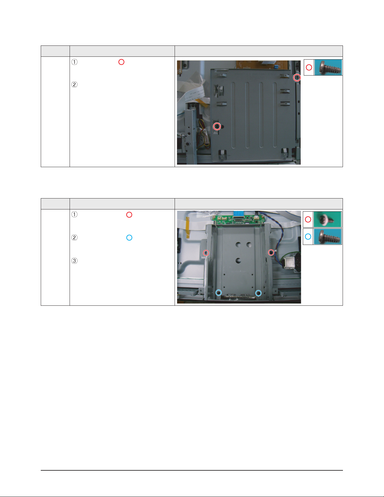
3-1-4 Separation of BRACKET-PCB
Part Name Description Description Photo
Bracket
PCB
Remove screw.( )
: BH,+,B,M4,L3,ZPC(BLK)
Remove the BRACKET-PCB.
3-1-5 Separation of ASSY BRACKET 42"/50"
Part Name Description Description Photo
Bracket
Remove 2 screws. ( )
: BH,+,PT,S Tite,M4,L10,ZPC(BLK)
Remove 2 screws. ( )
: BH,+,B,M4,L3,ZPC(BLK)
Remove Bracket.
3-1-7 Separation of ASSY SPEAKER P
Part Name Description Description Photo
Speaker
Remove 4 screws.( )
: BH,+,WP,B,M4.0,L3,ZPC(BLK),
SWRCH18A
Remove the Speaker.
The photo is for 42".
50" is very similiar with 42".
Disassembly & Reassembly
3-4 Samsung Electronics
3-1-6 Separation of ASSY BRACKET P-WALL
Part Name Description Description Photo
42"
Wall
Bracket
Remove 2 screws. ( )
: BH,+,B,M4,L3,ZPC(BLK)
Remove 4 screws. ( )
: BH,+,S,M4,L10,ZPC(BLK)
Remove Wall Bracket.
: Please lay the PDP panel face down
on a soft surface when separating front
cover.
50"
Wall
Bracket
Remove 2 screws. ( )
: BH,+,B,M4,L3,ZPC(BLK)
Remove 4 screws. ( )
: BH,+,S,M4,L10,ZPC(BLK)
Remove Wall Bracket.
!
Disassembly & Reassembly
Samsung Electronics 3-5
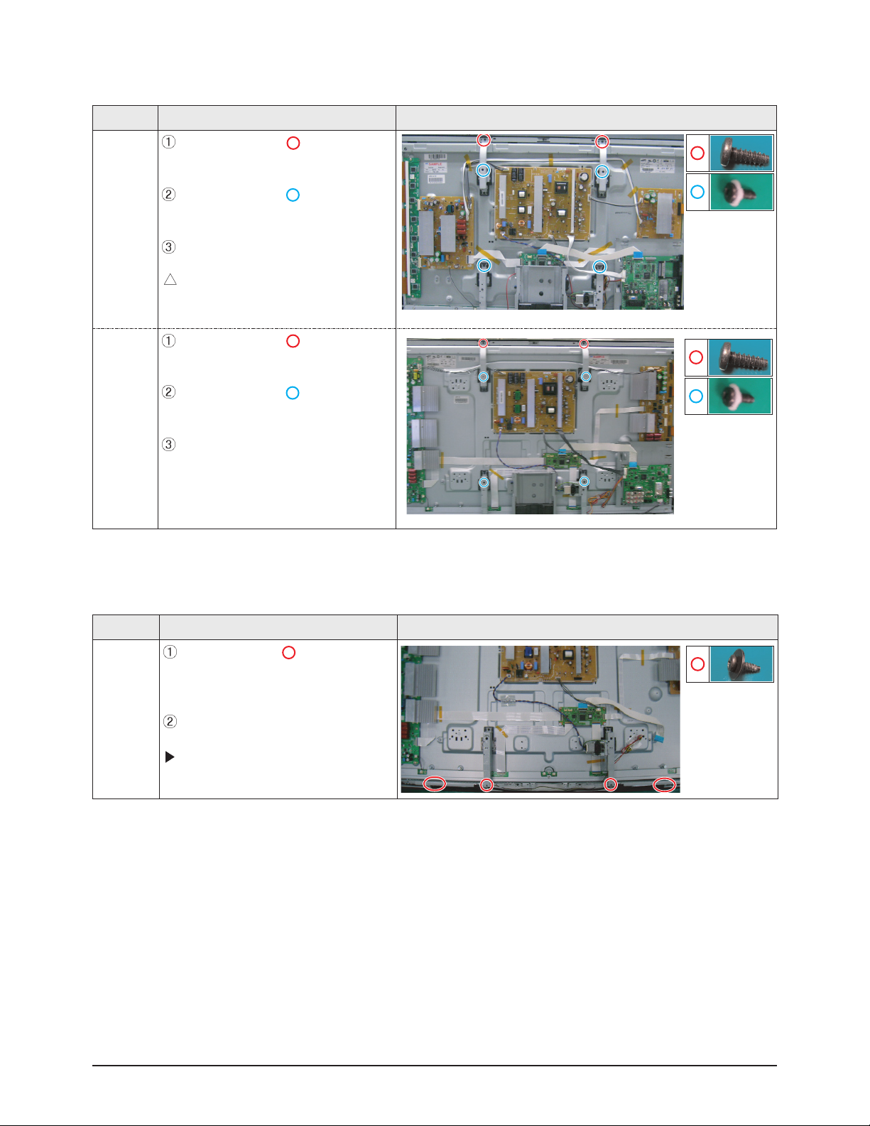
3-1-8 Separation of SMPS-PDP TV
Part Name Description Description Photo
42"
SMPS
Detach all connectors from the SMPS.
Remove 6 screws.
: PH,+,WWP,M3,L8,NI PLT
Remove the SMPS.
: Wear gloves when handling the power
board as there may be some remaining
electrical charge in the capacitor.
Specifically, avoid touching any part of
the capacitor.
50"
SMPS
Detach all connectors from the SMPS.
Remove 6 screws.
: PH,+,WWP,M3,L8,NI PLT
Remove the SMPS.
3-1-9 Separation of ASSY PDP MODULE P-LOGIC MAIN BOARD
Part Name Description Description Photo
Logic
Board
Detach all connectors from the Logic
Main Board.
Remove 2 screws.
: WSP,PH,+,M3,L8,NI PLT
Remove the Logic Main Board.
!

Disassembly & Reassembly
3-6 Samsung Electronics
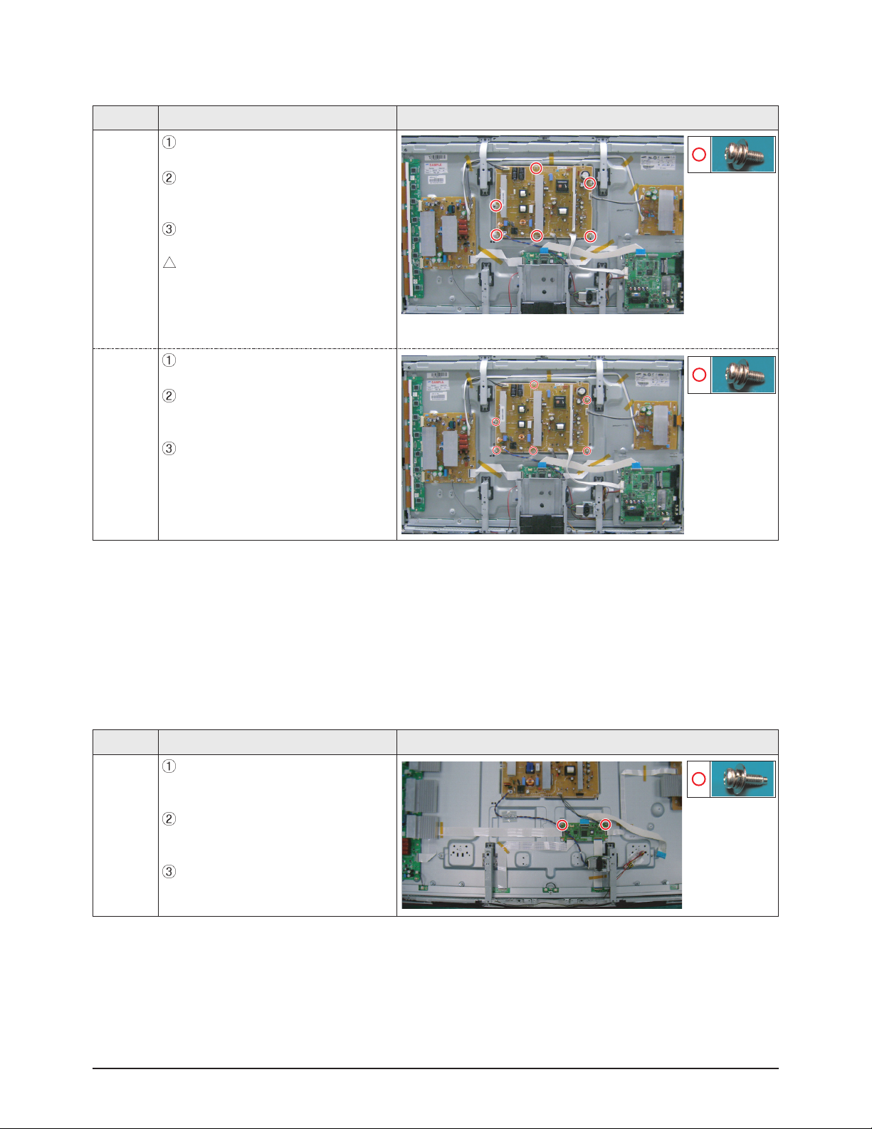
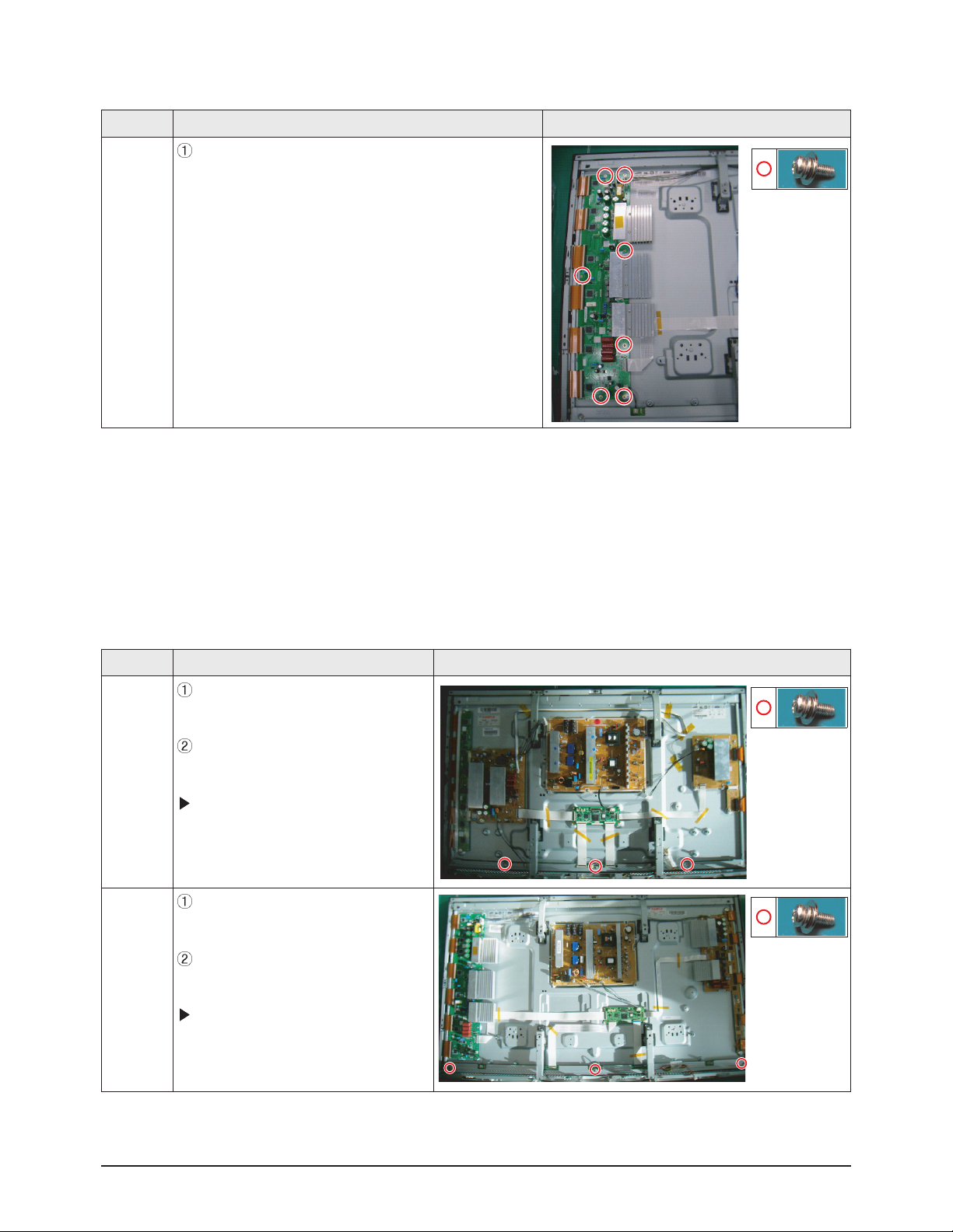
3-1-10 Separation of ASSY PDP MODULE P-X MAIN BOARD
Part Name Description Description Photo
42"
Flat able
Detach all Connectors from the X Main Board.
To separate the Flat Cable of the X-Board, press the
upper and the lower sides of the connector.
: Pinch the sides, but then push down in the ribbon, it
should slide out after that.
42"
X-Main
Board
Remove 7 screws.
: PH,+,WWP,M3,L8,NI PLT
Remove the X-Main Board.
50"
X-Main
Board
Remove the X-Main Board.
!
Disassembly & Reassembly
Samsung Electronics 3-7
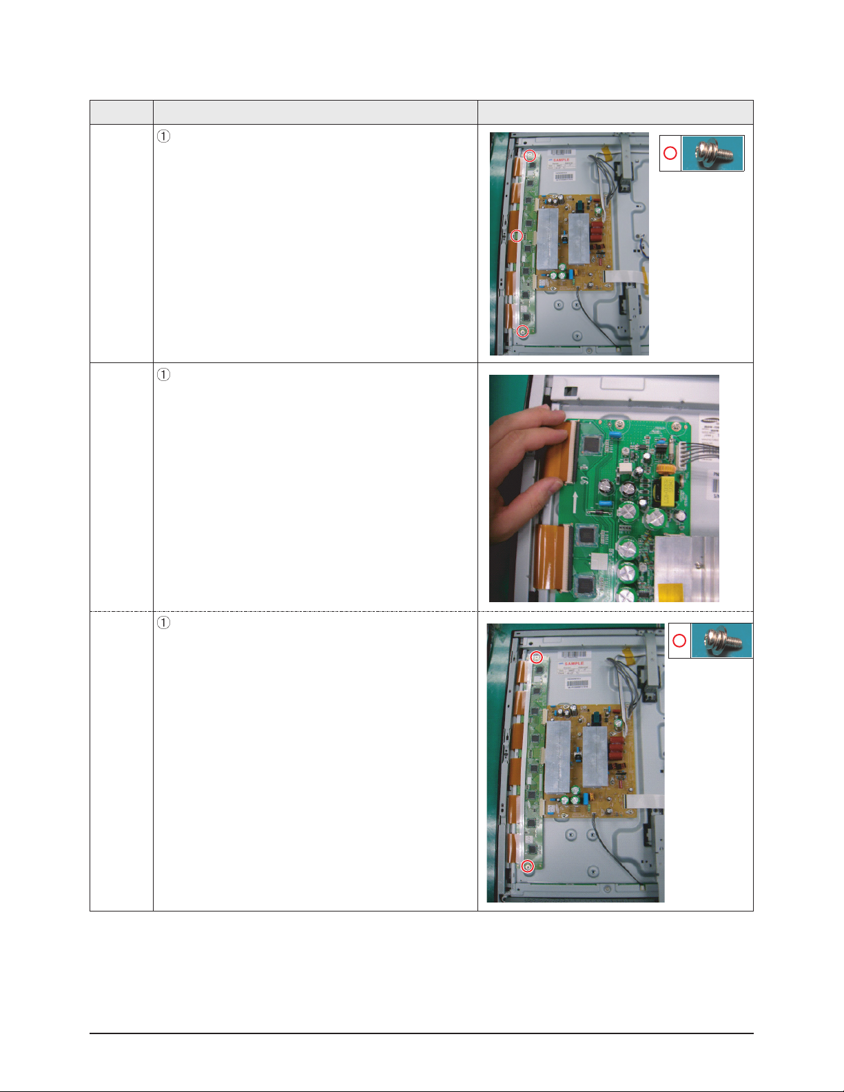
3-1-11 Separation of ASSY PDP MODULE P-Y MAIN BOARD
Part Name Description Description Photo
42"
Flat Cable
Detach the scan board connectors from the panel .
50"
Flat Cable
Detach the scan board connectors from the panel .
42"
Y-Scan
Board
Remove 2 screws.
: PH,+,WWP,M3,L8,NI PLT
3-1-12 Separation of ASSY PDP MODULE P-ADDRESS BUFFER BOARD
Part Name Description Description Photo
42"
Buffer
board
shield
Remove 3 screws.
: PH,+,WWP,M3,L8,NI PLT
Remove the still bar.
Before removing the still bar, you should
lift up the panel a little.
50"
Buffer
board
shield
Remove 3 screws.
: PH,+,WWP,M3,L8,NI PLT
Remove the still bar.
Before removing the still bar, you should
lift up the panel a little.
Disassembly & Reassembly
3-8 Samsung Electronics
Part Name Description Description Photo
50"
Y-Scan
Board
Remove 7 screws.
: PH,+,WWP,M3,L8,NI PLT

Disassembly & Reassembly
Samsung Electronics 3-9
3-1-13 Separation of ASSY PANEL BRACKETS
Part Name Description Description Photo
Panel
Brackets
Remove 7 screws. ( )
: BH,+,B,M4,L3,ZPC(BLK)
Remove the Side Panel Brackets.

3-10 Samsung Electronics
MEMO
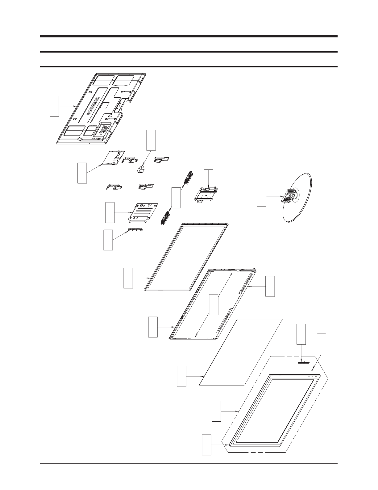
Exploded View & Part List
5. Exploded View & Part List
5-1 PS42B450B1WXXC Exploded View
M0013
FT532
M0014
M0523
M0412
T0289
T0044
M0149
T0175
M0027
M0150
M0146
M0175
T0603
T0456
T0003
M0112
Samsung Electronics5-1
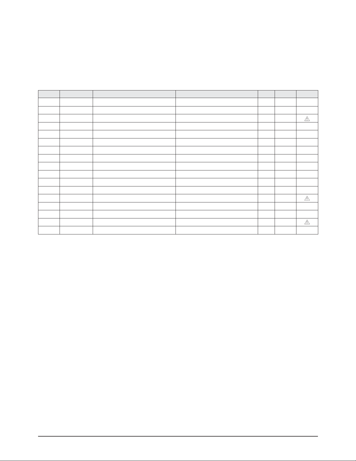
Exploded View & Part List
Loc. No. Code No. Description Specification Q'ty SA/SNA Remark
FT532 2901-001548 FILTER-EMI AC LINE 250V,6A,UL, CSA, VDE, 1 S.A
M0013 BN96-10205D ASSY COVER P-REAR PB450 42,PCM,BKM-P703, 1 S.N.A
M0014 BN94-02844A ASSY PCB MISC-MAIN PS42B450B1WXXC 1 S.A
M0027 BN96-09927A ASSY STAND P-BASE 42/50(PB450) 1 S.A
M0112 BN63-05331E COVER-FRONT 42PB450,ABS+PMMA,HB,ROSE BLA 1 S.A
M0146 BN96-10229A ASSY BRACKET P-FILTER SIDE PB450 42,SECC 2 S.N.A
M0149 BN96-10198A ASSY BRACKET P-FILTER TOP PB450 42,SECC 1 S.N.A
M0150 BN96-10199A ASSY BRACKET P-FILTER BOTTOM PB450 42,SE 1 S.N.A
M0175 BN96-10377B ASSY BOARD P-TOUCH FUNCTION&IR PS42B451B 1 S.A
M0412 BN96-10232A ASSY BRACKET P-PCB PB450 42,SECC,T0.6 1 S.N.A
M0523 BN96-10231A ASSY BRACKET P-SUPPORT STAND PB450 42,SE 1 S.N.A
T0003 BN96-10203E ASSY COVER P-FRONT PB450 42,ABS+PMMA,HB, 1 S.N.A
T0044 BN96-10452B ASSY PDP MODULE P SA42AX-YD11,PP42AB057B 1 S.A
T0175 BN96-09464A ASSY SPEAKER P 8ohm,4pin,10W,R:850 / L:3 1 S.A
T0289 BN63-05298A COVER-AV 50PB550,ABS HB,BLK(BK500) 1 S.A
T0456 BN67-00248A GLASS-FILTER EMI 42" P450,With AR, Witho 1 S.A
T0603 BN64-01013A WINDOW-RMC 42PB450,PC,VIOLET 1 S.N.A
5-2Samsung Electronics

Exploded View & Part List
5-2
PS50B450B1WXXC
M0013
M0014
Exploded View
FT532
M0523
M0412
T0289
T0044
M0149
T0175
M0027
M0150
M0146
M0175
T0603
T0456
T0003
M0112
Samsung Electronics5-3

Exploded View & Part List
Loc. No. Code No. Description Specification Q'ty SA/SNA Remark
FT532 2901-001557 FILTER-EMI AC LINE 250V,6A,UL, CSA, VDE, 1 S.A
M0013 BN96-10206D ASSY COVER P-REAR PB450 50,PCM,BKM-P703, 1 S.N.A
M0014 BN94-02845A ASSY PCB MISC-MAIN PS50B450B1WXXC 1 S.A
M0027 BN96-09927A ASSY STAND P-BASE 42/50(PB450) 1 S.A
M0112 BN63-05334E COVER-FRONT 50PB450,ABS+PMMA,HB,ROSE BLA 1 S.A
M0146 BN96-10235A ASSY BRACKET P-FILTER SIDE PB450 50,SECC 2 S.N.A
M0149 BN96-10233A ASSY BRACKET P-FILTER TOP PB450 50,SECC 1 S.N.A
M0150 BN96-10234A ASSY BRACKET P-FILTER BOTTOM PB450 50,SE 1 S.N.A
M0175 BN96-10377C ASSY BOARD P-TOUCH FUNCTION&IR PS42B451B 1 S.A
M0412 BN96-10232B ASSY BRACKET P-PCB PB450 50,SECC,T0.6 1 S.N.A
M0523 BN96-10231A ASSY BRACKET P-SUPPORT STAND PB450 42,SE 1 S.N.A
T0003 BN96-10204E ASSY COVER P-FRONT PB450 50,ABS+PMMA,HB, 1 S.N.A
T0044 BN96-09931A ASSY PDP MODULE P S50HW-YD11,PP50HB056B, 1 S.A
T0175 BN96-09464B ASSY SPEAKER P 8ohm,4pin,10W,R:850 / L:3 1 S.A
T0289 BN63-05298A COVER-AV 50PB550,ABS HB,BLK(BK500) 1 S.A
T0456 BN67-00225A GLASS-EMI FILTER 50" P450, with AR, W/O 1 S.A
T0603 BN64-01013A WINDOW-RMC 42PB450,PC,VIOLET 1 S.N.A
5-4Samsung Electronics

Exploded View & Part List
5-3 PS42B450B1WXXC Service Item
※ This is the list which is available to repair the real material at the time of service.
Loc. No. Code No. Description Specification Q'ty Remark
M0013 BN96-10205D ASSY COVER P-REAR PB450 42,PCM,BKM-P703, 1
M0014 BN94-02844A ASSY PCB MISC-MAIN PS42B450B1WXXC 1
M0027 BN96-09927A ASSY STAND P-BASE 42/50(PB450) 1
M0154 BN96-09752A ASSY PDP P-Y-MAIN BUFFER BOARD S42AX-YB0 1
M2893 BN39-00802C LEAD CONNECTOR HPT4264H,UL1617#22,24P/24 1
T0003 BN96-10203E ASSY COVER P-FRONT PB450 42,ABS+PMMA,HB, 1
T0037 BN96-09753A ASSY PDP P-LOGIC MAIN BOARD S42AX-YB07,P 1
T0044 BN96-10452B ASSY PDP MODULE P SA42AX-YD11,PP42AB057B 1
T0045 BN96-09749A ASSY PDP P-X-MAIN BOARD S42AX-YB07,PL42A 1
T0045 BN96-09750A ASSY PDP P-X-MAIN BUFFER BOARD S42AX-YB0 1
T0074 BN59-00863A REMOCON LCD450,TM950,EUROPE,WHITE,48 1
T0175 BN96-09464A ASSY SPEAKER P 8ohm,4pin,10W,R:850 / L:3 1
T0262 BN96-09751A ASSY PDP P-Y-MAIN BOARD S42AX-YB07,PL42A 1
T0764 BN44-00273B SMPS-PDP TV 42U1_DY,AC/DC,314.23W,AC90~2 1
T0937 BN96-09754A ASSY PDP P-ADDRESS E-BUFFER BO S42AX-YB0 1
Samsung Electronics5-5

Exploded View & Part List
5-4
PS50B450B1WXXC
Loc. No. Code No. Description Specification Q'ty Remark
M0013 BN96-10206D ASSY COVER P-REAR PB450 50,PCM,BKM-P703, 1
M0014 BN94-02845A ASSY PCB MISC-MAIN PS50B450B1WXXC 1
M0027 BN96-09927A ASSY STAND P-BASE 42/50(PB450) 1
M2893 BN39-00802S LEAD CONNECTOR LILY2 50",UL1007#26,24p/2 1
T0003 BN96-10204E ASSY COVER P-FRONT PB450 50,ABS+PMMA,HB, 1
T0037 BN96-09739A ASSY PDP P-LOGIC MAIN BOARD S50HW-YB04,P 1
T0039 BN96-09741A ASSY PDP P-ADDRESS F-BUFFER BO S50HW-YB0 1
T0044 BN96-09931A ASSY PDP MODULE P S50HW-YD11,PP50HB056B, 1
T0045 BN96-09736A ASSY PDP P-X-MAIN BOARD S50HW-YB04,PL50H 1
T0045 BN96-09737A ASSY PDP P-X-MAIN BUFFER BOARD S50HW-YB0 1
T0074 BN59-00863A REMOCON LCD450,TM950,EUROPE,WHITE,48 1
T0175 BN96-09464B ASSY SPEAKER P 8ohm,4pin,10W,R:850 / L:3 1
T0262 BN96-09738A ASSY PDP P-Y-MAIN BOARD S50HW-YB04,PL50H 1
T0764 BN44-00274B SMPS-PDP TV 50U1_DY,P0842A,AC/DC,439.03W 1
T0937 BN96-09740A ASSY PDP P-ADDRESS E-BUFFER BO S50HW-YB0 1
Service Item
※ This is the list which is available to repair the real material at the time of service.
5-6Samsung Electronics

MEMO
Samsung Electronics5-7

1. Precaution
To avoid possible damage, electric shocks or exposure to radiation, follow the instructions below with regard to safety, installation, service and ESD.
1-1 Safety Precautions
Precaution
1. Make sure all protective devices are properly installed
including non-metallic handles and compartment covers
when installing or re-installing the chassis or chassis
assemblies.
2. Make sure that no gaps exist between the cabinets for
children to insert their fingers in to prevent children from
receiving electric shocks. Gaps mentioned above include
ventilation holes between the PDP module and the cabinet mask, and the improper installation of the rear cabinet.
Errors may occur when the resistance is below 1.0 ㏁ or
over 5.2 ㏁.
In these cases, make sure that the device is repaired
before sending it back to the customer.
3. Check for Electricity Leakage (Figure 1-1)
Warning: Do not use an insulated transformer for checking the leakage. Use only those current leakage testers
or mirroring systems that comply with ANSIC 101.1 and
the Underwriter Laboratory's specifications (UL1410,
59.7).
(READING SHOULD
DEVICE
UNDER
TEST
EXPOSED METAL
2-WIRE CORD
ALSO TEST WITH
PLUG REVERSED
(USING AC ADAPTER
PLUG AS REQUIRED)
TEST ALL
SURFACES
LEAKAGE
CURRENT
TESTER
NOT BE ABOVE
0.5mA)
EARTH
GROUND
Fig. 1-1 AC Leakage Test
4. A high voltage is maintained within the specified limits
using safety parts, calibration and tolerances. When
voltage exceeds the specified limits, check each special
part.
5. Warning for Engineering Changes:
Never make any changes or additions to the circuit
design or the internal part for this product.
Ex: Do not add any audio or video accessory
connectors. This might cause physical damage.
Furthermore, any changes or additions to the original
design/engineering will invalidate the warranty.
6. Warning - Hot Chassis:
Some TV chassis are directly connected to one end of
the AC power cord for electrical reasons.
Without insulated transformers, the product can only be
repaired safely when the chassis is connected to the
earth end of the AC power source.
To make sure the AC power cord is properly connected,
follow the instructions below. Use the voltmeter to
measure the voltage between the chassis and the
earth ground. If the measurement is over 1.0V, unplug
the AC power cord and change the polarity before reinserting it. Measure the voltage between the chassis
and the ground again.
7. Some TV chassis are shipped with an additional secondary grounding system. The secondary system is
adjacent to the AC power line. These two grounding
systems are separated in the circuit using an unbreakable/unchangeable insulation material.
8. When any parts, material or wiring appear overheated or
damaged, replace them with new immediately. When
any damage or overheating is detected, correct this
immediately and make a regular check of possible
errors.
9. Check for the original shape of the lead, especially that
of the antenna wiring, any sharp edges, the AC power
and the high voltage power. Carefully check if the wiring
is too tight, incorrectly placed or loose. Never change the
space between the part and the printed circuit board.
Check the AC power cord for possible damages. Keep
the part or the lead away from any heat-emitting
materials.
Samsung Electronics 1-1

Precaution
10. Safety Indication:
Some electrical circuits or device related materials
require special attention to their safety features, which
cannot be viewed by the naked eye. If an original part is
replaced with another irregular one, the safety or
protective features will be lost even if the new one has a
higher voltage or more watts.
Critical safety parts should be bracketed with ( ).
!
Use only regular parts for replacements (in particular,
flame resistance and dielectric strength specifications).
Irregular parts or materials may cause electric shock or
fire.
1-2 Samsung Electronics

1-2 Servicing Precautions
Warning 1: First carefully read the "Safety Instruction" in this service manual.
When there is a conflict between the service and the safety instructions, follow the safety instruction at all times.
Warning 2: Any electrolytic capacitor with the wrong polarity will explode.
Precaution
1. The service instructions are printed on the cabinet, and
should be followed by any service personnel.
2. Make sure to unplug the AC power cord from the power
source before starting any repairs.
(a) Remove or re-install parts or assemblies.
(b) Disconnect the electric plug or connector, if any.
(c) Connect the test part in parallel with the electrolytic
capacitor.
3. Some parts are placed at a higher position than the
printed board. Insulated tubes or tapes are used for this
purpose. The internal wiring is clamped using buckles to
avoid contact with heat emitting parts. These parts are
installed back to their original position.
4. After the repair, make sure to check if the screws, parts
or cables are properly installed. Make sure no damage is
caused to the repaired part and its surroundings.
5. Check for insulation between the blade of the AC plug
and that of any conductive materials (i.e. the metal
panel, input terminal, earphone jack, etc).
6. Insulation Check Process: Unplug the power cord from
the AC source and turn the switch on. Connect the insulating resistance meter (500v) to the AC plug blade.
7. Any B+ interlock should not be damaged.
If the metal heat sink is not properly installed, no
connection to the AC power should be made.
8. Make sure the grounding lead of the tester is connected
to the chassis ground before connecting to the positive
lead. The ground lead of the tester should be removed
last.
9. Beware of risks of any current leakage coming into
contact with the high-capacity capacitor.
10. The sharp edges of the metal material may cause
physical damage, so protect yourself by wearing gloves
during the repair.
11. Due to the nature of plasma display panels, partial afterimages may appear if a still picture is displayed on the
screen for a long period of time.
This is caused by brightness deterioration due to the
storage effect of the panel, and to prevent this from
happening, we recommend that the brightness and contrast are reduced.
(e.g.) Contrast: 25, Brightness: 50
The insulating resistance between the blade of the AC
plug and that of the conductive material should be more
than 1 ㏁.
Samsung Electronics 1-3
Loading...