


LASER PRINTER
ML-1200 Series
ML-1210 / ML-1250 / ML-1220M
SERVICE Manual 
LASER PRINTER |
|
CONTENTS |
1. Precautions
2. Specifications
3. Disassembly and Reassembly
4. Troubleshooting
5. Exploded Views and Parts List
6. Block Diagram
7. Connection Diagram

This service manual is also provided on the web, the ITSELF system Samsung Electronics Co., Ltd.
http://itself.sec.samsung.co.kr
©Samsung Electronics Co.,Ltd. October. 2001 Printed in Korea.
VERSION NO. : 2.03 |
CODE : JC-0051A |

This manual is stated and provided for service description.
All rights reserved. Any parts of the information in this manual are prohibited from free duplication, use or translation without prior written approval except in cases allowed by the Copyright Act.
Specifications are subject to change without prior notice.
Samsung Electronics Digital Printing CS Group
Copyright (c) 2001. 5.
Precautions
1. Precautions
Please read the following carefully to prevent any accidents and not to damage the unit during service.
1-1 Safety Precautions
1.Safety Precautions
There are some electric or machinery parts with safety related property. If the parts replaced are different from the original, the safety may not function. Even if the part could allow higher voltage than that of the part used, do not replace it and use a regular product clarified in specifications.
2.Be careful not to leave a switch, a cover or a safety device out when reinstalling or assembling the product after repair.
3.Replacing Precautions
Do not change or add parts as you like. You cannot benefit from such a remodeled product at your will during the term of guarantee.
4.You must replace overheated or damaged parts or cords with regular products. Please solve the problem causing any damage or overheating and troubles beforehand.
Especially mind the safety on the part with this mark.
You must use regular parts described in specifications for the parts inflammable and where the current can be flown. Otherwise any hazard such as an electric shock or a fire could occur.
LASER STATEMENT (LASERTURVALLISUUS)
WARNING : NEVER OPERATE AND SERVICE THE PRINTER WITH THE PROTECTIVE COVER REMOVED FROM LASER/SCANNER ASSEMBLY. THE REFLECTIVE BEAM, ALTHOUGH INVISIBLE, CAN DAMAGE YOUR EYES.
Class 1 laser product
Luokan 1 laserlaite
Klass 1 laser apparat
Allonpituus 770-795nm
Teho 0.3mW±0.03mW
CAUTION INVISIBLE LASER RADIATION WHEN THIS COVER OPEN. DO NOT OPEN THIS COVER.
VORSICHT UNSICHTBARE LASERSTRAHLUNG, WENN ABDECKUNG GEOFFNET. NIGHT DEM STRAHL AUSSETZEN.
ATTENTION REYONNEMENT LASER INVISIBLE EN CAS D’OUVERTURE. EXPOSITION DANGERUSE AU FAISCEAU.
ATTENZIONE RADIAZIONE LASER INVISIBLE IN CASO DI APERTURA. EVITARE L’ESPOSIZONE LA FASCIO.
PRECAUCION REDIACION LASER INVISIBLE CUANDO SE ABRE. EVITAR EXPONERSE AL RAYO.
CAUTION : Avoid exposure to invisible laser radiation when the development unit is not installed.
1-2 Precautions on Disassembly and Reassembly
Very careful precautions should be taken when replacing parts. Before replacing, please check cables because you cannot put the cables that you removed for replacing parts into the proper place if you would not make sure of where they were connected and in which condition.
Please do the following before disassembling for a repair or replacement of parts.
1.Pull out paper cassette, printer cartridge installed. Especially careful not to be scratched by the surface of developer or not to expose them to light.
2.Turn the power switch off.
3.Take out the power plug, printer cable from the printer.
4.Use only the same type of part as original when replacing parts.
5.Do not force to open or fasten plastic material components.
6.Be careful that small parts such as screws should not get in the printer.
7.When disassembling, assembling, also observe small components are located in place.
8.If you uncover and turn the machine over to replace some parts, toner or paper particles may contaminate the LSU window. Protect the LSU window with clean paper.
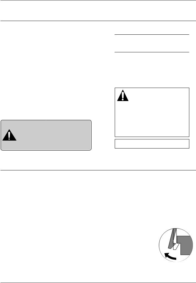
Releasing Plastic Latches
Many of parts are held in place with plastic latches. The latches break easily : release them carefully.
To remove such parts, press the hook end of the latch away from the part to which it is latched.
Samsung Electronics |
1-1 |
Precautions
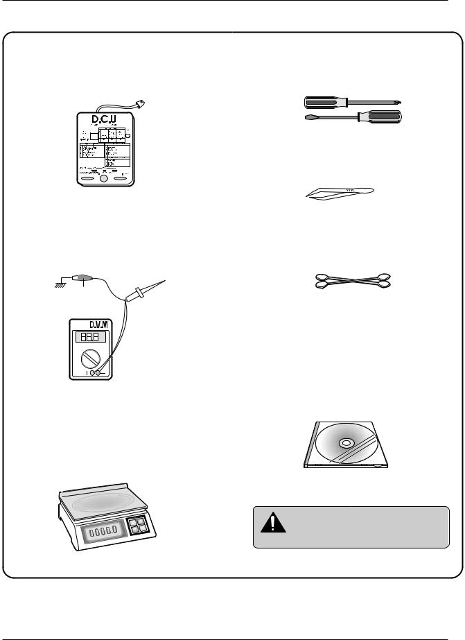
1-3 Tools for Troubleshooting
The following tools are recommended for safe and smooth troubleshooting described in this service manual.
1 DCU(Diagnostic Control Unit)
Standard: Test equipment to diagnose the Laser printer supplied by Samsung Electronics.
2 DVM(Digital Volt Meter)
Standard: Indicates more than 3 digits.
Ground
3 Electronic Scale
Standard: Equipment to check the weight of consumables(toner cartridge) supplied by Samsung Electronics. (The gram unit can be measured.)
4 DriverStandard: "-" type, "+" type (M3 long, M3 short, M2 long, M2 short).
5 PinsetStandard: For general home use, small type.
6 Cotton Swab
Standard: For general home use, for medical service.
7 Cleaning Equipments a IPA(Isopropyl Alcohol)dry cloth or a soft stuff neutral detergent.
8 Software(Driver) installation CD ROM
Mind your hands not to be touched when you disassemble and reassemble PBAASS'Y,
Note such as the main board, SMPS, HVPS.
1-2 |
Samsung Electronics |

Specifications
2. Specifications
|
|
ML-1210 (ML-1220M) |
|
ML-1250 |
Engine |
Speed |
12ppm |
|
|
|
|
|
|
|
|
Resolution |
600 x 600 dpi |
|
1200 x 600 dpi |
|
|
|
|
|
|
FROP(Fist Power On Time) |
Under 12.5 sec |
|
|
|
|
|
|
|
|
Warm-Up Time |
30 sec |
|
|
|
|
|
|
|
|
Power Consumption |
25W (Print), 10W (Sleep) |
||
|
|
|
|
|
|
Dimension |
329 x 355 x 231 mm (13” x 14” x 9.1”) |
||
|
|
|
|
|
|
Weight |
Max 6.5Kg (With Toner Cartridge) |
||
Controller |
Processor |
Jupiter 366MHz |
|
61200 66MHz |
|
Memory |
8MB Equivalent |
|
4MB |
|
Emulation |
SmartGDI |
|
PCL6 |
|
|
|
|
|
|
Interface |
IEEE1284, USB (ML-1220M : USB ONLY) |
||
|
|
|
|
|
|
OS Support |
Windows 95/98/2000/Me/NT, |
||
|
|
Linux(Radhat 6.0), iMac(Mac OS 8.0) |
||
|
|
|
|
|
|
N/W |
External |
|
|
Paper |
Input |
150 sheets |
|
|
|
Output |
100 sheets |
|
|
|
|
|
|
|
|
Manual |
1 sheet |
|
|
|
|
|
|
|
|
Media Type |
A4, Letter. Legal, Executive, B5, A5, Folio, |
||
|
|
7 3/4(Monarch), #10, DL, C5, C6, B5 |
||
Toner |
Type |
Single Cartridge |
|
|
|
Life |
2,500 sheets |
|
|
|
|
|
|
|
|
Cartridge |
2,500 (Initial : 1,000) |
||
|
|
|
|
|
|
Pick up Roller |
60,000 |
|
|
|
Feed Roller |
60,000 |
|
|
|
|
|
|
|
|
Transfer Roller |
60,000 |
|
|
|
|
|
|
|
|
Fuser |
40,000 |
|
|
|
|
|
|
|
User interface |
Key & LED |
3Key, 4LEDs |
|
|
|
LCD |
No |
|
|
|
|
|
|
|
|
Toner Save |
YES |
|
|
|
|
|
|
|
|
Reprint |
YES |
|
|
|
|
|
|
|
Samsung Electronics |
2-1 |

Disassembly and Reassembly
3. Disassembly and Reassembly
3-1 Cover Assembly
3-1-1 Front Cover
1. Pull the both side of the cover to open.
4.Remove a screw of the front cover PCB and remove the connector, then remove the cover.
2. Remove a screw and remove the stopper that holds the printer cover.
3-1-2 Other Covers
1. Before you remove other covers, you should remove the Front cover in advance.
2. Rear Cover : Remove the cover in the direction of |
a . |
3. Top Cover : Remove the cover in the direction of |
b . |
4. Side Cover L, R : Remove the cover in the direction of c .
3. Loosen the right lower part of the cover, then push the cover in the direction of arrow to loosen the left lower part.
Samsung Electronics |
3-1 |
Disassembly and Reassembly
3-2 LED Panel PBA
1. Before you remove other covers, you should remove. |
3. Remove two screws, and remove LED panel. |
• Front Cover (see [3-1 Main Cover])
2. Remove two screws of PCB cover, and widen the hooks( a b c ) to remove.
4. Remove PCB from the PCB cover.
3-3 LSU(Laser Scanning Unit)
1.Before you remove LSU, you should remove front cover, rear cover and top cover.
•Main Cover (see [3-1 Main Cover])
3.Remove two connectors from the LSU, then remove the LSU.
2. Remove three screws securing the LSU.
3-2 |
Samsung Electronics |
Disassembly and Reassembly
3-4 Transfer Roller
1. Open the front cover.
2. Use a proper tool("-" type screwdriver) to pull the one end of the roller slightly, then take it out.
3-5 Motor Assembly
1. Before you remove the motor assembly, you should remove:
• Main Cover (see [3-1 Main Cover])
• Shield Engine Assembly
2. Remove five screws securing the motor assembly and remove a connector from engine board(Engine board and SMPS board are integrated), then take the motor assembly out.
Samsung Electronics |
3-3 |
Disassembly and Reassembly
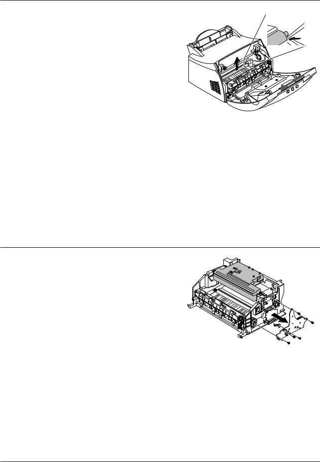
3-6 HVPS Board
1. Before you remove HVPS board, you should remove:
•Main Cover (see [3-1 Main Cover])
2. Remove four screws and a connector from HVPS board, then take the board out.
When you reassemble the HVPS board, make |
Terminal |
|
Note sure that five terminals should be put in place. |
||
|
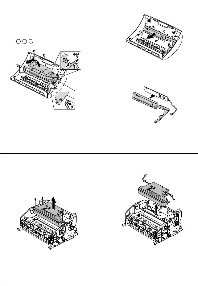
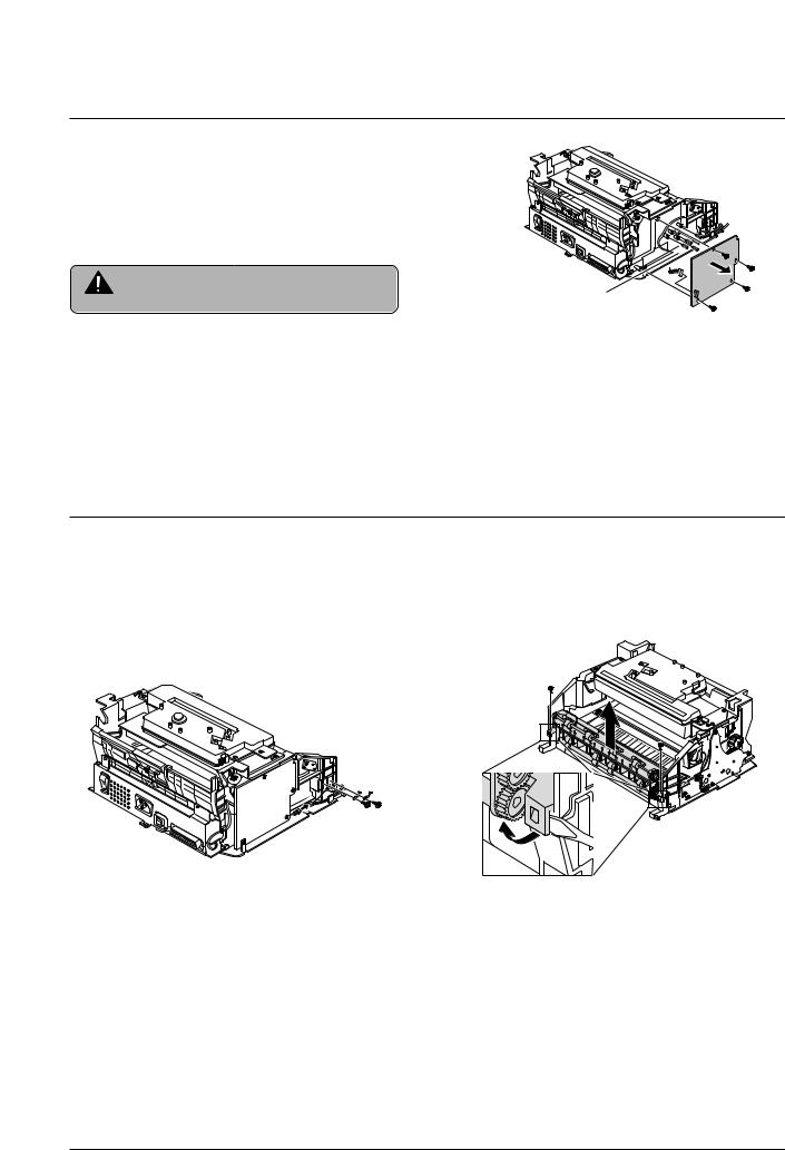
3-7 Fuser Assembly
1.Before remove fuser assembly, you should remove:
•Main Cover (see [3-1 Main Cover])
2.Remove two ground screws and a connector as illustrated.
3.Remove two screws and unplug a fuser assembly harness. Then use a " - " screwdriver to unlatch the fuser assembly to remove.
3-4 |
Samsung Electronics |
Disassembly and Reassembly
3-8 Thermostat and Halogen Lamp
1.Remove a screw from the fuser assembly and remove the thermostat cover, then remove two screws securing the thermostat.
3. Take the halogen lamp out from the Heat Roller.
When you reassemble the halogen lamp,
Note handle it with care as it is fragile.
2.Remove two screws from the fuser assembly, and take the Heat Roller out.
Samsung Electronics |
3-5 |
Disassembly and Reassembly
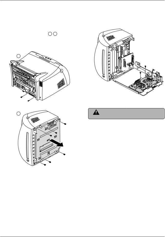
3-9 SMPS Board
1.Before you remove the SMPS board, you should remove:
•Main Cover (see [3-1 Main Cover])
3.Unplug connectors from the main board and connectors from SMPS, then remove the SMPS. Remove four screws from SMPS and remove the SMPS board.
2. Remove screws in the order of a b then remove the shield engine assembly.
a
b |
The Engine board and SMPS board are |
|
integrated in a body. |
||
Note |
3-6 |
Samsung Electronics |
Disassembly and Reassembly
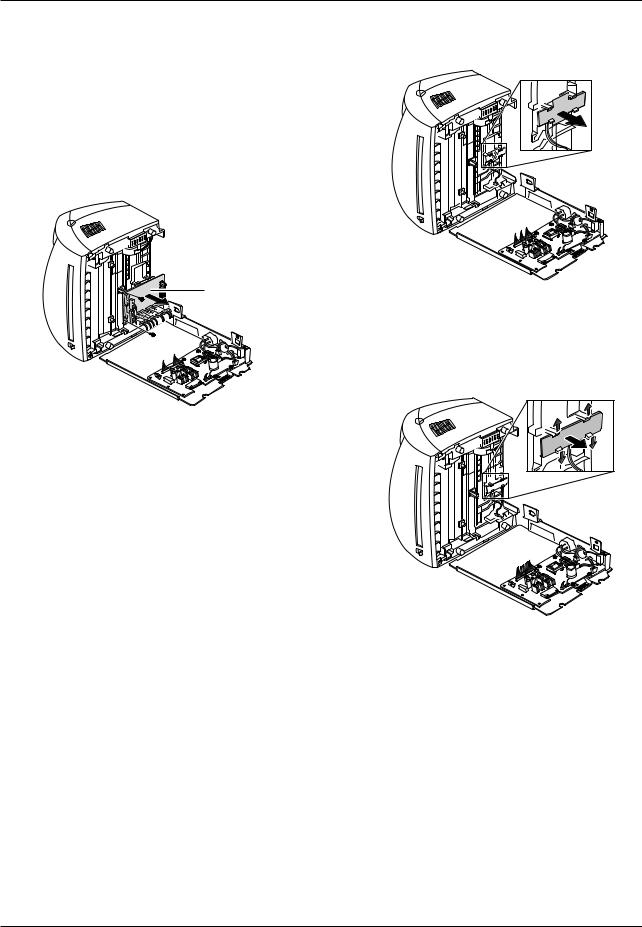
3-10 Main Board and Sensor Board
1.Before you remove the main board, you should remove:
•Main Cover (see [3-1 Main Cover])
•SMPS board (see [3-9 SMPS Board])
2.Remove two screws from the main board and unplug all of connectors, then remove the board.
3.Release four snap-fits securing the insulator engine board and then remove the insulator.
Main B’d
4. Release four snap-fits securing the sensor board and then remove the sensor board.
Samsung Electronics |
3-7 |

Troubleshooting
4. Troubleshooting
4-1 How to use DCU |
|
|
4-1-1 |
DCU Setup ...................................... |
Page(4-2) |
4-1-2 Code ................................................ |
Page(4-2) |
|
4-1-3 |
Self Diagnostic Mode...................... |
Page(4-3) |
4-1-4 |
Self Test Button ................................ |
Page(4-4) |
4-1-5 Paper Path Layout ........................... |
Page(4-4) |
|
4-2 The cause and solution of Bad image |
||
4-2-1 |
Vertical Black Line and Band .......... |
Page(4-5) |
4-2-2 |
Vertical White Line ........................... |
Page(4-5) |
4-2-3 |
Horizontal Black Band ..................... |
Page(4-6) |
4-2-4 |
Black/White Spot.............................. |
Page(4-6) |
4-2-5 |
Light Image....................................... |
Page(4-7) |
4-2-6 Dark Image or a Black..................... |
Page(4-7) |
|
4-2-7 Uneven Density................................ |
Page(4-8) |
|
4-2-8 Background ...................................... |
Page(4-8) |
|
4-2-9 |
Ghost (1)........................................... |
Page(4-9) |
4-2-10 Ghost (2).......................................... |
Page(4-9) |
|
4-2-11 Ghost (3) .......................................... |
Page(4-10) |
|
4-2-12 Ghost (4) ......................................... |
Page(4-10) |
|
4-2-13 Satins on the Face of Page............ |
Page(4-10) |
|
4-2-14 Satins on Back of Page.................. |
Page(4-11) |
|
4-2-15 Blank Page Print out (1) ................. |
Page(4-11) |
|
4-2-16 Blank Page Print out (2) ................. |
Page(4-11) |
|
4-3 The cause and solution of the bad discharge
4-3-1 |
Wrong Print Position ....................... |
Page(4-12) |
4-3-2 |
JAM 0............................................... |
Page(4-12) |
4-3-3 |
JAM 1............................................... |
Page(4-13) |
4-3-4 |
JAM 2............................................... |
Page(4-13) |
4-3-5 Multi-Feeding................................... |
Page(4-14) |
|
4-3-6 Paper rolled in the fuser ................. |
Page(4-14) |
|
4-3-7 |
OPC ................................................. |
Page(4-15) |
4-4 The cause and solution of the malfunction
4-4-1 All LEDs blinking (Fuser Error)........Page(4-16)
4-4-2 All LEDs blinking (SCAN ERROR) .Page(4-16)
4-4-3 |
Not function of the gear of the fuser due to |
|
|
melting away..................................... |
Page(4-17) |
4-4-4 Paper Empty..................................... |
Page(4-17) |
|
4-4-5 |
Paper Empty without indication....... |
Page(4-17) |
4-4-6 Cover Open...................................... |
Page(4-18) |
|
4-4-7 No lamp on when the cover is open |
||
|
........................................................... |
Page(4-18) |
4-4-8 |
Defective motor operation ............... |
Page(4-19) |
4-4-9 |
No Power.......................................... |
Page(4-19) |
4-4-10 Vertical Line Getting Curved ......... |
Page(4-20) |
|
4-5 Toner Cartridge Service
4-5-1 |
Precautions on Safe-keeping of Toner Cartridge |
|
..........................................................Page(4-21) |
4-5-2 |
Service for the Life of Toner Cartridge |
|
..........................................................Page(4-21) |
4-5-3 |
Service for Judgement of Inferior Expendables |
|
and the Standard of Guarantee .....Page(4-21) |
4-5-4 |
Signs and Measures at Poor toner cartridge |
|
..........................................................Page(4-22) |
4-6 The cause and solutions of bad environment of the software
4-6-1 |
The printer is not working (1)........... |
Page(4-25) |
4-6-2 |
The printer is not working (2) ......... |
Page(4-26) |
4-6-3 |
Abnormal Printing............................. |
Page(4-27) |
4-6-4 |
SPOOL Error ................................... |
Page(4-28) |
Samsung Electronics |
4-1 |

Troubleshooting
4-1 How to use DCU
4-1-1 DCU Setup
You can examine the malfunction of the printer. To perform DCU, open the front discharge cover and leave the connect the harness wire(10 pin/4 pin) to the CN10(4 pin) of the Main control board.
4-1-2 Code
Connect DCU to the printer and turn the power on. It show 7 LED on the panel and each code tells the function of the printer.
Normal Code
While printing or warming up, it indicate the position of the paper
61 |
Warm up |
The printer is on, the cover is open or close. |
00-05 |
Ready(kind of paper) |
The printer is ready, the paper is detected when the first paper is printed. |
|
|
00: Legal , 01: Letter , 02: A4 , 03: EXEC , 04: B5 , 05: Folio |
20 |
Print Start |
The engine controller received the print order from the video controller. |
30 |
Feed Sensor On |
The paper is passing out of the Feed Sensor. |
40 |
Feed Sensor off |
The paper has passed out of the Feed Sensor. |
50 |
Paper Out |
The paper has passed out of Exit Sensor. |
69 |
Sleep Mode |
The fuser power turned off to minimize the power consumption. |
|
|
|
Error Code
When detecting the malfunction, the printing is stopped to indicate error code.
60, 62, 68 |
Fuser Error |
The error in the fuser occurred. There is a short circuit in the thermistor and the |
|
|
thermostat while printing, Low Temperature Error occurs. |
|
|
• 60: Open Fuser Error |
|
|
• 62: Low Heat Error |
|
|
• 68: Over Heat Error |
64 |
Cover Open |
The Printer Cover is open or Toner Cartridge not installed. |
70 |
No Paper |
No paper in the paper cassette. |
71 |
Paper Jam 0 |
The front part of paper is jammed between pickup unit and Feed sensor. |
72 |
Paper Jam 1 |
The front part of paper is jammed between the Discharge sensor and Feed sensor. |
73 |
Paper Jam 2 |
The front part of paper is jammed just after passing through the discharge sensor. |
95 |
LSU Not Ready |
LSU Scanner Motor not ready or Hsync signal not output. |
|
|
|
4-2 |
Samsung Electronics |

Troubleshooting
4-1-3 Self Diagnostic Mode
If Error code occurs due to malfunction of the printer, perform Self Diagnostic Mode to solve the problem.
The printer works only in the self-test mode to solve the malfunction problem.
To enter the self-test mode, turn the power on pressing the buttons of [Down], [Shift] and [Stop] at the same time. Release the button within 2 or 3 seconds if 78 shows in the DCU. If 00 shows in the DCU, press the button [Up] or [Shift] to select the self+test , and press the button of [Enter] to operate. To stop, press the button of [shift] and [Enter] together.
00Main Motor Operating System
Only the main motor is in operation.
01 |
Main High Voltage On(THV-) |
|
|
-1550 voltage output by MHV terminal. |
Caution : High voltage probe should be used. |
|
|
|
02 |
Transfer High Voltage(-)On(THV-) |
|
|
-1300 voltage output by MHV terminal. |
Caution : High voltage probe should be used. |
|
|
|
03 |
Transfer High Voltage (+)Reference on (THV +) |
|
|
1300 voltage output by MHV terminal. |
Caution : High voltage probe should be used. |
|
|
|
04 |
DEV/supply High Voltage : DEV/Supply High Voltage Test. |
|
|
The left one of the three LEDs in the self-test panel is on when DEV high voltage Supply high voltage output |
|
|
by each HV terminal. Press the [Up] button to switch the voltage. The middle and right one of the three LEDs |
|
|
are on and -530 voltage output by DEV HV terminal. |
Caution : High voltage probe should be used. |
05LSU Operating System
The scanning motor of LSU is in operation, the right LED of the three buttons on. Press the [Up] button to Check LD. LD is functioning and the middle button is on. If the LD is normal, all LEDs are on.
06Pickup clutch on
The Solenoid in the printer is in operation. To stop the operation, Press the button [shift] and [Enter] together.
07 Pempty/PWIDTH/New CRU Sensor Test : Pempty/PWIDTH.HEW CRU sensor test.
If activate the Actuator of the PEMPTY/PWIDTH Sensor, the left and right of the three LEDs are on. If you install new toner Cartridge in this mode, the right LED is on.
08Feed & Exit Sensor Test
Test the Feed sensor and Discharge sensor in the same way as '06'.
09Cover Open Sensor Test
The same way as code '06'.
10Fuser Test
If the [Enter] button pressed, the right LED is on and temperature of the fuser is up to READY Mode. If the [Up] button pressed, the middle LED is on and temperature of the fuser is up to Printing Mode.
If you press the button once more, the left LED is on and temperature of the fuser is up to overheat Mode.
11Hot Burn Test
If the [enter] button pressed, the printer is continuously printing without detection. Turn the power off to stop operation.
12.Cleaning Mode Print Mode
Print the paper to clean the OPC Drum in the Cartridge.
Samsung Electronics |
4-3 |
Troubleshooting
13.THV(+) TRIGGER. ALL HV
All high voltage output by each HV terminal and LSU and the fan is in operation. In this mode, electronic resistance of transfer roller and high voltage is detected. If no toner cartridge in the printer, output of THV is +199V ~ + 2100V.
14.PTL Test
Indicates the PTL LED.
15.Fan Test
Indicates the function of the fan.
4-1-4 Self Test Button
If the Self-Test button pressed, vertical lines are printed.
Turn the power on while pressing this button, '89' shows in the DCU and the printer is warming up. After warming-up the printer is in READY Mode, and '88' shows in the DCU. In this mode, without any detection, the printer begins printing(trial printing and data from the PC). It is convenient to use this mode when the engine malfunction is detected in the control board.
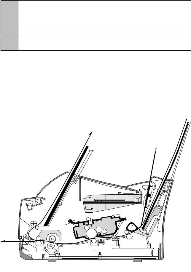
4-1-5 Paper Path Layout
|
|
(100 |
SHEETS) |
|
PAPER |
|
|
RECORDED |
|
|
|
|
|
|
FACE DOWN
SHEET 1 MANUAL
LSU
KNOCK UP
|
(150 |
SHEETS) |
PAPER |
|
|
|
|
|
RECORDED |
|
|
EXIT 2 |
PICK UP |
|
|
|
CARTRIDGE |
CR |
DR |
|
|
FUSER |
|
|
|
SR |
IDLE |
|
|
OPC |
|
|
|
H R/L |
|
|
|
FACE UP |
|
FEED |
EMPTY SEN |
|
|
||
|
|
|
|
TR |
|
FEED SEN |
|
|
PTL |
|
|
|
|
|
|
EXIT 1 |
|
SENSOR BOARD |
|
Pr R/L |
MAIN BOARD |
|
|
EXIT SENSOR |
|
SMPS |
|
|
|
|
|
SHIELD |
|
|
SHIELD |
4-4 |
Samsung Electronics |

Troubleshooting
4-2 The cause and solution of Bad image
4-2-1 Vertical Black Line and Band
• Description
Digital Printer
Digital Printer
Digital Printer
Digital Printer
Digital Printer
1.Straight thin black vertical line occurs in the printing.
2.Dark black vertical band occur in the printing.
|
Check and Cause |
|
Solution |
1. |
Damaged develop roller in the Developer |
1. |
If causes 1 and 2 occur in the developer |
|
or deformed Doctor-blade. |
|
cartridge, replace the developer and try to |
|
|
|
print out. |
2. |
Scratched surface of the discharge roller |
2. |
Replace the transfer roller if occurred as |
|
in the developer, or heavily accumulated |
|
No. 3. |
|
foreign matters between the discharge |
|
|
|
roller and fur transfer roller/ charge roller. |
|
|
3.Partly depression or deformation on the surface of the transfer roller.
4-2-2 Vertical White Line
• Description
Digital Printer
Digital Printer
Digital Printer 
Digital Printer
Digital Printer
White vertical voids in the image.
Check and Cause |
|
Solution |
|
|
|
1. Foreign matter stuck onto the window of |
1. |
Foreign matter stuck onto the window : |
internal lenses of LSU mirror. |
|
Clean the LSU window with recommend- |
|
|
ed cleaner(IPA) Clean the window with a |
|
|
clean cotton swab. |
2. Foreign matter or toner particles between |
|
|
the developer roller and blade. |
2. |
Foreign matter in the LSU : Open the |
(In case the life of the developer has |
|
cover of LSU and clean with a cotton |
been expired, white lines occur in front of |
|
swab on the surface of the reflex mirror. |
the image.) |
|
|
3. It may occur when Burr and foreign sub- |
3. |
No 3. : Remove the foreign matter and |
stances are on the window of the devel- |
|
burr of the exposure window. |
oper frame. |
|
|
4. If the fuser is defective, voids occur peri- |
4. |
No. 4. : Open the front cover and check |
odically at the top of a black image. |
|
ribs that corresponds to the position of |
|
|
the voids. Remove if found. |
|
5. |
If the problems are not solved, check to |
|
|
see if the weight of the developer is |
|
|
below 670g. If so, replace the developer |
|
|
cartridge. |
|
|
|
Samsung Electronics |
4-5 |
Troubleshooting
4-2-3 Horizontal Black Band
• Description
Digital Printer
Digital Printer
Digital Printer
Digital Printer
Digital Printer
1. Dark or blurry horizontal stripes occur in the printing periodically. (They may not occur periodically.)
Check and Cause |
|
Solution |
|
|
|
|
|
1. Bad contacts of the voltage terminals to |
1. |
Clean each voltage terminal of the Charge, |
|
developer. |
|
|
Supply, Develop and Transfer roller. |
|
|
|
(remove the toner particles and paper par- |
|
|
|
ticles) |
2. The rollers of developer may be stained. |
2. |
Clean the right Gear that has relatively |
|
Charge roller |
= 37 mm |
|
small gap of the teeth in the OPC. |
Supply roller |
= 27 mm |
|
|
Develop roller = 32 mm |
|
|
|
Transfer roller |
= 47 mm |
|
|
|
|
3. |
If the malfunction persists, replace the |
|
|
|
developer. |
|
|
|
|
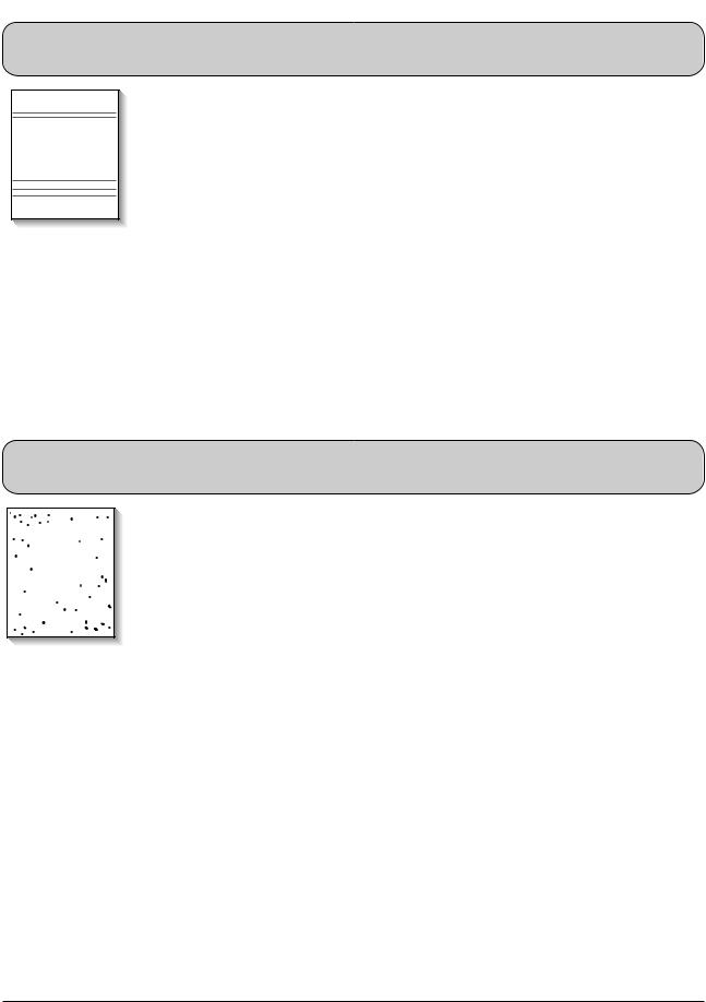
4-2-4 Black/White Spot
• Description
 Digital Printer
Digital Printer 
 Digital Printer
Digital Printer
Digital Printer
1.Dark or blurry black spots occur periodically in the printing.
2.White spots occur periodically in the printing.
Check and Cause |
Solution |
|
|
1. If dark or blurry black spots occur periodi- |
1. Run OPC cleaning Mode Print and run the |
cally, the rollers in the Developer may be |
Self-test 2 or 3 times. |
contaminated with foreign matte or paper |
|
particles. |
|
( Charge roller : 37 mm interval |
|
OPC drum : 75mm interval) |
|
2. If faded areas or voids occur in a black |
2. In case of 75mm interval unremovable in 1, |
image at intervals of 75 mm, or black |
cleanly remove foreign substances stuck on |
spots occur elsewhere, the OPC drum |
the OPC location equivalent to black spots |
surface is damaged. |
and white spots with a dry duster. |
3. If a black image is partially broken, the |
3. The transfer roller guarantees 50,000 |
transfer voltage is abnormal or the trans- |
sheets printing. If the roller's life is expired, |
fer roller's life has expired. |
replace it. |
|
4. In case of 37mm interval unremovable in 1, |
|
take measures as to replace the developer |
|
cartridge and try to print out. |
|
5. Clean the inside of the set against the paper |
|
particles and foreign matter in order not to |
|
cause the trouble. |
|
|
4-6 |
Samsung Electronics |

Troubleshooting
4-2-5 Light Image
• Description
Digital Printer
Digital Printer
Digital Printer
Digital Printer
Digital Printer
The printed image is light, with no ghost.
Check and Cause |
Solution |
|
|
1. Develop roller is stained when the toner |
1. Check if the Toner Save mode is off. |
of developer cartridge is almost con- |
|
sumed. |
|
2. Ambient temperature is below than 10°C. |
2. Replace the developer cartridge and try to |
|
print out. |
|
3. Wait 30 minutes after printer is powered on |
|
before you start printing. |
3. Bad contact caused by the toner stains |
|
between the high voltage terminal in the |
|
HVPS and the one in the set. |
4. Clean up the contaminated area by the |
|
toner. |
4. Abnormal output from the HVPS. |
|
(Run self-test and check 1~4) |
|
|
5. Replace the HVPS if the problems are not |
|
solved by the above four directions. |
|
( Service parts : Figure 11, Chapter 5) |
|
|
4-2-6 Dark Image or a Black
• Description
Digital Printer
Digital Printer
Digital Printer
Digital Printer
Digital Printer
The printed image is dark.
|
Check and Cause |
|
Solution |
|
|
|
|
1. |
No charge voltage in the engine board. |
1. Clean the high voltage charge terminal. |
|
|
( Perform DCU diagnostic code 01) |
|
|
2. |
Charge voltage is not turned on due to |
2. |
Check the state of the connector which |
|
the bad contacts between power supply |
|
connects the engine board and HVPS. |
|
in the side of the Developer and charge |
|
|
|
terminal of HVPS. |
|
|
|
|
3. |
Replace the HVPS if not solved by the |
|
|
|
above direction 1 and 2. |
|
|
|
|
Samsung Electronics |
4-7 |
 Loading...