


CONFIDENTIAL
LCD-TV
Chassis Model
AL29JO LT29A13W
AL40JO LT40A13W
SERVICEManual
LCD-TV
1. Precautions
2. Product Specifications
3. Disassembly &
4. Troubleshooting
5. Exploded View & Parts
6. Electrical Parts List
7. Block Diagram
8. Wiring Diagram
9. Schematic Diagrams
10. Panel Description

CONFIDENTIAL
1 Precautions
Follow these safety, servicing and ESD precautions to prevent damage and to protect against potential hazards such as electrical shock.
1-1 Safety Precautions
1-1-1 Warnings
1.For continued safety, do not attempt to modify the circuit board.
2.Disconnect the AC power and DC Power Jack before servicing.
1-1-2 Servicing the LCD Monitor
1.When servicing the LCD Monitor disconnect the AC line cord from the AC outlet.
|
|
|
|
(READING SHOULD |
|||
|
|
|
|
NOT BE ABOVE 0.5mA) |
|||
|
|
|
|
|
|
|
|
|
|
|
|
|
|
|
|
|
|
|
|
|
LEAKAGE |
|
|
DEVICE |
|
|
|
|
|
||
|
|
|
|
CURRENT |
|
||
UNDER |
|
|
|
|
|
||
|
|
|
|
TESTER |
|
||
TEST |
|
|
|
|
|
|
|
|
|
|
TEST ALL |
||||
|
|
EXPOSED METAL |
|||||
|
|
|
SURFACES |
||||
|
2-WIRE CORD |
||||||
2.It is essential that service technicians have an accurate voltage meter available at all times. Check the calibration of this meter periodically.
1-1-3 Fire and Shock Hazard
Before returning the monitor to the user, perform the following safety checks:
1.Inspect each lead dress to make certain that the leads are not pinched or that hardware is not lodged between the chassis and other metal parts in the monitor.
2.Inspect all protective devices such as nonmetallic control knobs, insulating materials, cabinet backs, adjustment and compartment covers or shields, isolation resistor-capacitor networks, mechanical insulators, etc.
3.Leakage Current Hot Check (Figure 1-1):
WARNING:
Do not use an isolation transformer during this test.
Use a leakage current tester or a metering system that complies with American National Standards Institute (ANSI C101.1, Leakage Current for Appliances), and Underwriters Laboratories (UL Publication UL1410, 59.7).
ALSO TEST WITH
PLUG REVERSED
(USING AC ADAPTER
PLUG AS REQUIRED) EARTH GROUND
Figure 1-1. Leakage Current Test Circuit
4.With the unit completely reassembled, plug the AC line cord directly into a 120V AC outlet. With the unit’s AC switch first in the ON position and then OFF, measure the current between a known earth ground (metal water pipe, conduit, etc.) and all exposed metal parts, including: metal cabinets, screwheads and control shafts. The current measured should not exceed 0.5 milliamp. Reverse the power-plug prongs in the AC outlet and repeat
the test.
1-1-4 Product Safety Notices
Some electrical and mechanical parts have special safety-related characteristics which are often not evident from visual inspection. The protection they give may not be obtained by replacing them with components rated for higher voltage, wattage, etc. Parts that have special safety characteristics are identified by
! on schematics and parts lists. A substitute replacement that does not have the same safety characteristics as the recommended replacement part might create shock, fire and / or other hazards. Product safety is under review continuously and new instructions are issued whenever appropriate.
LT29A13W/LT40A13W |
1-1 |

1 Precautions
1-2 Servicing Precautions
CONFIDENTIAL
WARNING: An electrolytic capacitor installed with the wrong polarity might explode.
Caution: Before servicing units covered by this service manual, read and follow the Safety Precautions section of this manual.
Note: If unforeseen circumstances create conflict between the following servicing precautions and any of the safety precautions, always follow the safety precautions.
1-2-1 General Servicing Precautions
1.Always unplug the unit’s AC power cord from the AC power source and disconnect the DC Power Jack before attempting to:
(a)remove or reinstall any component or assembly,
(b)disconnect PCB plugs or connectors, (c) connect a test component in parallel with an electrolytic capacitor.
2.Some components are raised above the printed circuit board for safety. An insulation tube or tape is sometimes used. The internal wiring is sometimes clamped to prevent contact with thermally hot components. Reinstall all such elements to their original position.
3.After servicing, always check that the screws, components and wiring have been correctly reinstalled. Make sure that the area around the serviced part has not been damaged.
4.Check the insulation between the blades of the AC plug and accessible conductive parts (examples: metal panels, input terminals and earphone jacks).
5.Insulation Checking Procedure: Disconnect the power cord from the AC source and turn the power switch ON. Connect an insulation resistance meter (500 V) to the blades of the AC plug.
The insulation resistance between each blade of the AC plug and accessible conductive parts (see above) should be greater than 1 megohm.
6.Always connect a test instrument’s ground lead to the instrument chassis ground before connecting the positive lead; always remove the instrument’s ground lead last.
1-3 Electrostatically Sensitive Devices (ESD) Precautions
Some semiconductor (solid state) devices can be easily damaged by static electricity. Such components are commonly called Electrostatically Sensitive Devices (ESD). Examples of typical ESD are integrated circuits and some field-effect transistors. The following techniques will reduce the incidence of component damage caused by static electricity.
1.Immediately before handling any semiconductor components or assemblies, drain the electrostatic charge from your body by touching a known earth ground. Alternatively, wear a discharging wriststrap device. To avoid a shock hazard, be sure to remove the wrist strap before applying power to the monitor.
2.After removing an ESD-equipped assembly, place it on a conductive surface such as aluminum foil to prevent accumulation of an electrostatic charge.
3.Do not use freon-propelled chemicals. These can generate electrical charges sufficient to damage ESDs.
4.Use only a grounded-tip soldering iron to solder or desolder ESDs.
5.Use only an anti-static solder removal device. Some solder removal devices not classified as “anti-static” can generate electrical charges sufficient to damage ESDs.
6.Do not remove a replacement ESD from its protective package until you are ready to install it. Most replacement ESDs are packaged with leads that are electrically shorted together by conductive foam, aluminum foil or other conductive materials.
7.Immediately before removing the protective material from the leads of a replacement ESD, touch the protective material to the chassis or circuit assembly into which the device will be installed.
Caution: Be sure no power is applied to the chassis or circuit and observe all other safety precautions.
8.Minimize body motions when handling unpackaged replacement ESDs. Motions such as brushing clothes together, or lifting your foot from a carpeted floor can generate enough static electricity to damage an ESD.
1-2 |
LT29A13W/LT40A13W |

CONFIDENTIAL
2 Product Specifications
2-1 Specifications
Item |
|
Description |
|
|
|
|
|
|
LT29A13W |
LT40A13W |
|
|
|
|
|
LCD Panel |
TFT-LCD panel, RGB vertical stripe, normally black |
TFT-LCD panel, RGB vertical stripe, normally black |
|
|
transmissive, (29 -Inch) viewable, 0.4935 mm pixel pitch |
transmissive, (40-Inch) viewable, 0.6735 mm pixel pitch |
|
|
|
|
|
Scanning Frequency |
Horizontal : 30 KHz ~ 61 KHz |
|
|
|
Vertical : 56 Hz ~ 75 Hz |
|
|
|
|
|
|
Display Colors |
16,777,216 colors |
|
|
|
|
|
|
Maximum Resolution |
Horizontal : 1280 Pixels |
|
|
|
Vertical : 768 Pixels |
|
|
|
|
|
|
Input Video Signal |
Analog, 0.7 Vp-p ± 5% positive at 75 Ω , |
|
|
|
internally terminated |
|
|
|
|
|
|
Input Sync Signal |
Type : Seperate H/V sync, Composite H/V, Sync-on-Green |
||
|
Level : TTL level |
|
|
|
|
|
|
AC power voltage & Frequency |
AC 90 ~ 240V 60 Hz/50 Hz ± 3 Hz, DC 28V / 8A |
|
|
|
|
|
|
Power Consumption |
135W (max) |
200W (max) |
|
|
|
|
|
Dimensions |
|
|
|
Unit (W x D x H) |
29.9 x 20.0 x 1.9 Inches (760 x 506 x 49.0 mm) |
39.6 x 28.1 x 2.3 Inches (1006 x 713 x 58.0 mm) |
|
Carton (W x D x H) |
29.9 x 22.4 x 7.7 Inches (760 x 569 x 195 mm) |
39.6 x 29.4 x 11.8 Inches (1006 x 747 x 300 mm) |
|
|
37.8 x 22.4 x 7.7 Inches (961 x 569 x 195 mm) |
49.1 x 29.4 x 11.8 Inches (1248 x 747 x 300 mm) |
|
|
|
|
|
Weight (Net / Gross) |
11.2 kg (24.7 lbs) |
21.5 kg (47.4 lbs) |
|
|
13.7 kg (30.2 lbs) |
28.0 kg (61.7 lbs) |
|
|
16.0 kg (35.3 lbs) |
32.0 kg (70.5 lbs) |
|
|
|
|
|
Environmental Considerations |
Operating Temperature : 50°F ~ 104°F (10°C ~ 40°C) |
||
|
Humidity : 10 % ~ 80 % |
|
|
|
Storage Temperature : -4°F ~ 113°F (-20°C ~ 45°C) |
||
|
Humidity : 5 % ~ 95 % |
|
|
|
|
|
|
TV System |
Color |
|
NTSC-M |
|
|
|
|
|
Sound |
|
BTSC, A2 STEREO, EIAJ |
|
|
|
|
Antenna Input |
75Ω , Coaxial Cable |
|
|
|
|
|
|
Sound Characteristics |
•Max Internal speaker Out : Right c 10 W / Leftc 10 W |
||
|
•Bass control Range : -6 ± -12dB ~ +6 ± 12dB |
|
|
|
•TREBLE control Range : -10 ± -12dB ~ +10 ± 12dB |
||
|
•Output frequency : RFc 80 Hz~15 KHz / A/Vc 80 Hz~20 KHz |
||
|
•Line out : RFc 80 Hz~15 KHz / A/Vc 80 Hz~20 KHz |
||
|
|
|
|
•Designs and specifications are subject to change without prior notice.
LT29A13W/LT40A13W |
2-1 |
2 Product Specifications
2-2 PC Timing Chart
CONFIDENTIAL
This section of the service manual describes the timing that the computer industry recognizes as standard for computer-generated video signals.
Table 2-1 Timing Chart
Mode |
VGA3/60 Hz |
VGA/72 Hz |
VGA/75 Hz |
SVGA/56 Hz |
SVGA/60 Hz |
SVGA/72 Hz |
SVGA/72 Hz |
Timing |
640 x 480 |
640 x 480 |
640 x 480 |
800 x 600 |
800 x 600 |
800 x 600 |
1280 x 768 |
|
|
|
|
|
|
|
|
|
|
|
|
|
|
|
|
fH (kHz) |
31.5 |
37.9 |
37.5 |
35.2 |
37.9 |
48.1 |
47.7 |
|
|
|
|
|
|
|
|
A pixels |
800 |
832 |
840 |
1024 |
1056 |
1040 |
1680 |
B pixels |
96 |
40 |
64 |
72 |
128 |
120 |
136 |
C pixels |
40 |
120 |
120 |
128 |
88 |
64 |
200 |
D pixels |
640 |
640 |
640 |
800 |
800 |
800 |
1280 |
E pixels |
8 |
16 |
16 |
24 |
40 |
56 |
64 |
|
|
|
|
|
|
|
|
fV (Hz) |
60.0 |
72.8 |
75.0 |
56.3 |
60.3 |
72.2 |
60 |
|
|
|
|
|
|
|
|
O liues |
525 |
520 |
500 |
625 |
628 |
666 |
795 |
P liues |
2 |
3 |
3 |
2 |
4 |
6 |
3 |
Q liues |
25 |
20 |
16 |
22 |
23 |
23 |
23 |
R liues |
480 |
480 |
480 |
600 |
600 |
600 |
768 |
S liues |
2 |
1 |
1 |
1 |
1 |
37 |
1 |
|
|
|
|
|
|
|
|
Clock |
|
|
|
|
|
|
|
Freq. |
25.175 |
31.500 |
31.500 |
36.000 |
40.000 |
50.000 |
80.136 |
(MHz) |
|
|
|
|
|
|
|
|
|
|
|
|
|
|
|
Polarity |
|
|
|
|
|
|
|
H.Sync |
Negative |
Negative |
Negative |
–/+ |
Positive |
Positive |
* |
V.Sync |
Negative |
Negative |
Negative |
–/+ |
Positive |
Positive |
* |
|
|
|
|
|
|
|
|
Remark |
Separate |
Separate |
Separate |
Separate |
Separate |
Separate |
Separate |
|
|
|
|
|
|
|
|
|
|
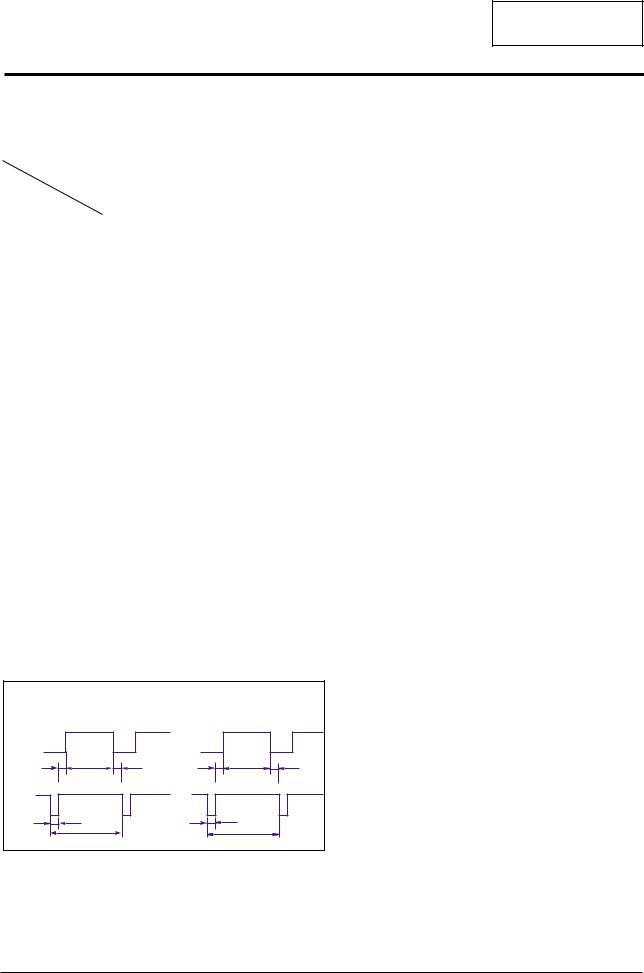
Separate Sync |
|
|
|
Horizontal |
|
|
Vertical |
|
|
Video |
|
|
Video |
|
|
C C |
DD |
E E |
Q Q |
R R |
S S |
Sync |
|
|
Sync |
|
|
|
B |
|
|
PP |
|
|
B |
|
|
|
|
|
A A |
|
|
O O |
|
A : Line time total |
B : Horizontal sync width |
O : Frame time total |
P : Vertical sync width |
C : Back porch |
D : Active time |
Q : Back porch |
R : Active time |
E : Front porch |
|
S : Front porch |
|
|
|
|
|
LTM295W/LTM405W |
2-2 |
2 Product Specifications
Table 2-2 Timing Chart (continued)
CONFIDENTIAL
Mode |
SVGA/75 Hz |
XGA/60 Hz |
XGA/70 Hz |
XGA/75 Hz |
Timing |
800 x 600 |
1024 x 768 |
1024 x 768 |
1024 x 768 |
|
|
|
|
|
|
|
|
|
|
fH (kHz) |
46.9 |
48.4 |
56.5 |
60.0 |
A pixels |
1056 |
1344 |
1328 |
1312 |
B pixels |
80 |
136 |
136 |
96 |
C pixels |
160 |
160 |
144 |
176 |
D pixels |
800 |
1024 |
1024 |
1024 |
E pixels |
16 |
24 |
24 |
16 |
fV (Hz) |
75.0 |
60.0 |
70.1 |
75.0 |
O liues |
625 |
806 |
806 |
800 |
P liues |
3 |
6 |
6 |
3 |
Q liues |
21 |
29 |
29 |
28 |
R liues |
600 |
768 |
768 |
768 |
S liues |
1 |
3 |
3 |
1 |
Clock |
|
|
|
|
Freq. |
49.500 |
65.000 |
75.000 |
78.750 |
(MHz) |
|
|
|
|
Polarity |
|
|
|
|
H.Sync |
Positive |
Negative |
Negative |
Positive |
V.Sync |
Positive |
Negative |
Negative |
Positive |
Remark |
Separate |
Separate |
Separate |
Separate |
|
|
|
|
|
|
|
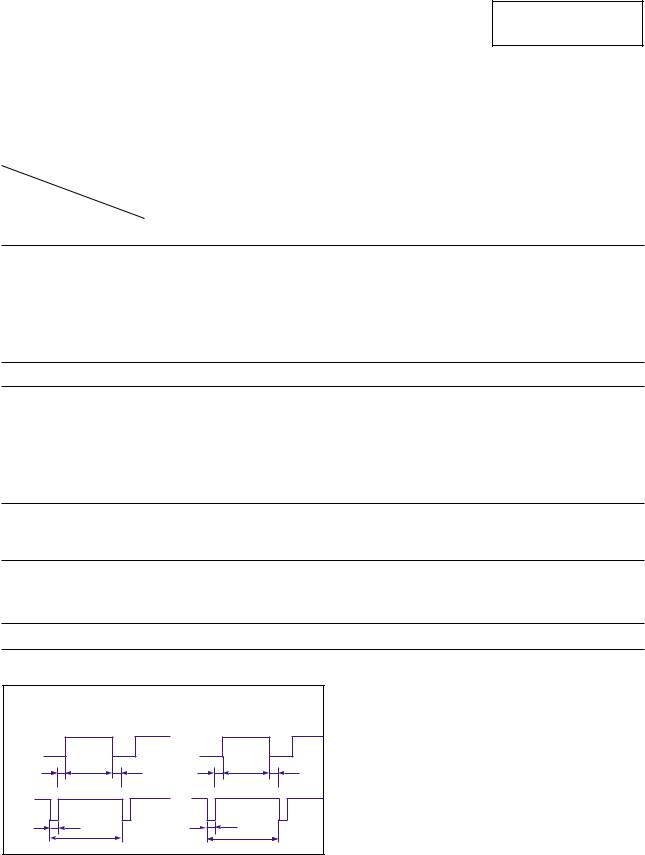
Separate Sync |
|
|
|
Horizontal |
|
|
Vertical |
|
|
Video |
|
|
Video |
|
|
C C |
DD |
E E |
Q Q |
R R |
S S |
Sync |
|
|
Sync |
|
|
|
B |
|
|
PP |
|
|
B |
|
|
|
|
|
A A |
|
|
O O |
|
A : Line time total |
B : Horizontal sync width |
O : Frame time total |
P : Vertical sync width |
C : Back porch |
D : Active time |
Q : Back porch |
R : Active time |
E : Front porch |
|
S : Front porch |
|
|
|
|
|
|
|
|
|
LT29A13W/LT40A13W |
2-3 |

2 Product Specifications
Memo
CONFIDENTIAL
2-4 |
LT29A13W/LT40A13W |
CONFIDENTIAL
3 Disassembly and Reassembly
This section of the service manual describes the disassembly and reassembly procedures for the LT29A13W/LT40A13W monitor.
WARNING: This monitor contains electrostatically sensitive devices. Use caution when handling these components.
3-1 Disassembly
Cautions:1. Disconnect the monitor from the power source before disassembly.
2.Follow these directions carefully; never use metal instruments to pry apart the cabinet.
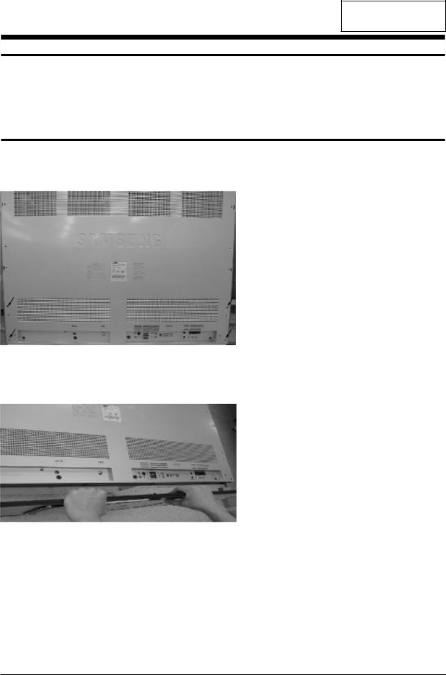
1.Remove 4 screws of the cover rear.
2. Remove the stand from LCD-TV.
LT29A13W/LT40A13W |
3-1 |
3 Disassembly and Reassembly |
|
CONFIDENTIAL |
|
|
|
|
|
|
|
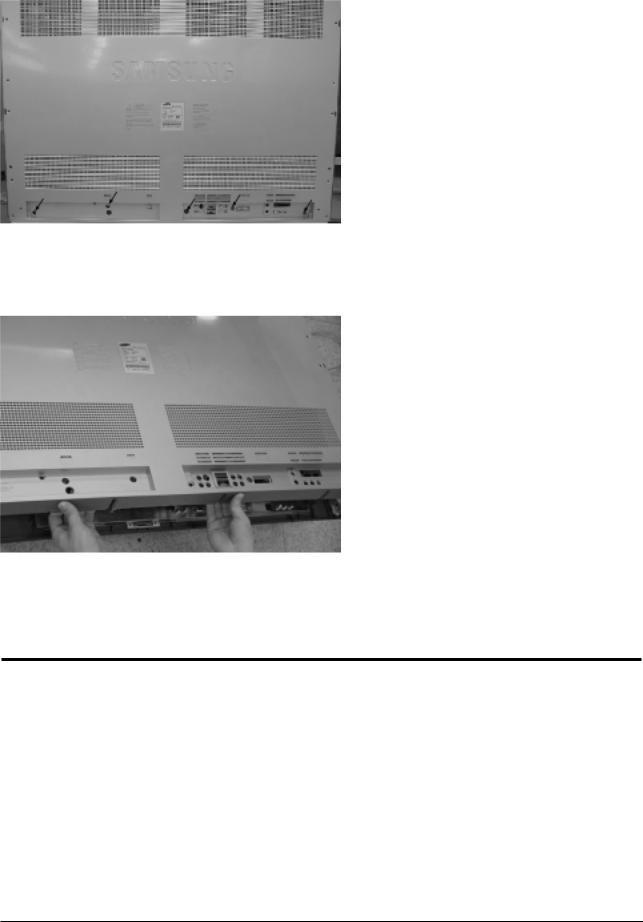
3. Remove 4 screws of the cover rear. |
|
4. Pull the cover rear.
3-2 Reassembly
Reassembly procedures are in the reverse order of Disassembly procedures.
3-2 |
LT29A13W/LT40A13W |

CONFIDENTIAL
Copyright
© 2002 by Samsung Electronics Co., Ltd.
All rights reserved.
This manual may not, in whole or in part, be copied, photocopied, reproduced, translated, or converted to any electronic or machine readable form without prior written permission of Samsung Electronics Co., Ltd.
LT29A13W/LT40A13W Service Manual
First edition October 2002.
Printed in Korea.
Trademarks
Samsung is the registered trademark of Samsung Electronics Co., Ltd.
LT29A13W/LT40A13W and MacMaster Cable Adapter are trademarks of Samsung Electronics Co., Ltd.
Macintosh, Centris, Quadra, Duo Douk, and Power Macintosh are trademarks of Apple Computer, Inc.
All other trademarks are the property of their respective owners.
ii |
LT29A13W/LT40A13W |
CONFIDENTIAL
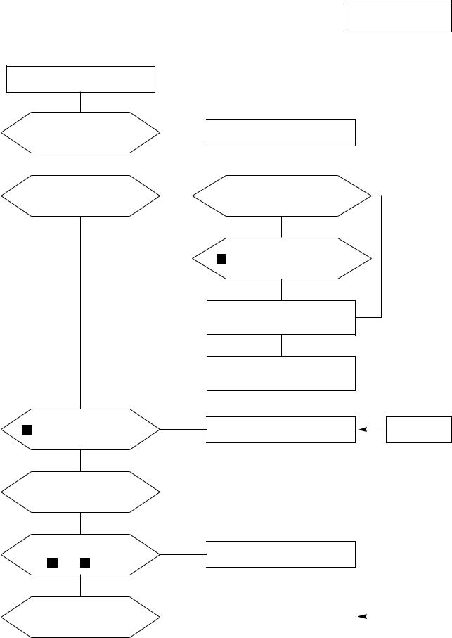
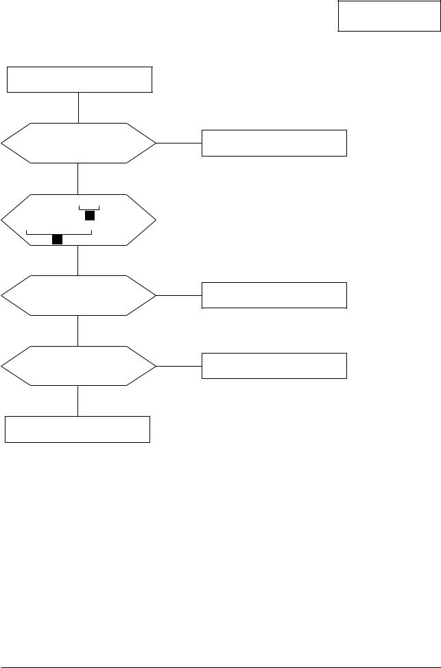
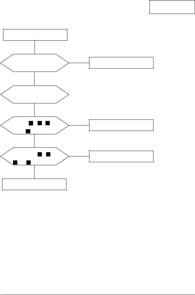
4 Troubleshooting
4-1-1 No Picture (Lamp off, LED on)
LED Green or amber and lamp off.
No
Check the adaptor output is 28V?
Yes
No
No
Check the 3rd Pin of IC904 is 12V?
Yes
No
Check R934 (BKLPW) is 3.3V?
Yes
No
Check C928 is 14V?
Change power adaptor. |
|
|
|
|
(BN44-00067B) |
|
|
|
|
|
|
|
|
|
Check the tuner board power is 28V? |
|
|
|
|
(29” : BN59-00321A, CN127 lst Pin) |
|
|
|
|
|
|
|
||
(40” : BN59-00323A, CN28 lst Pin) |
|
|
|
|
|
Yes |
|
|
|
|
|
|
|
|
|
|
|
|
No |
DC-DC defect. |
|
|
||
|
|
|
||
Change main board. |
|
|
|
|
(29” : BN94-00362A, 40” : BN94-00363A) |
|
|
|
|
|
|
|
|
|
Tuner board defect. |
|
|
|
|
Change tuner board. |
|
|
|
|
|
|
|
||
(29” : BN59-00321A, 40” : BN59-00323A) |
|
|
|
|
|
|
|
|
|
DC-DC defect. |
|
|
|
|
Change main board. |
|
|
|
|
|
|
|
|
|
|
|
|
|
|
DC-DC defect. |
|
|
|
|
Change main board. |
|
|
|
|
|
|
|
|
|
DC-DC defect.
Change main board.
Inverter defect contact HQ.
LT29A13W/LT40A13W |
4-1 |
4 Troubleshooting
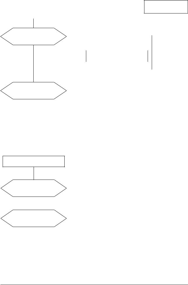
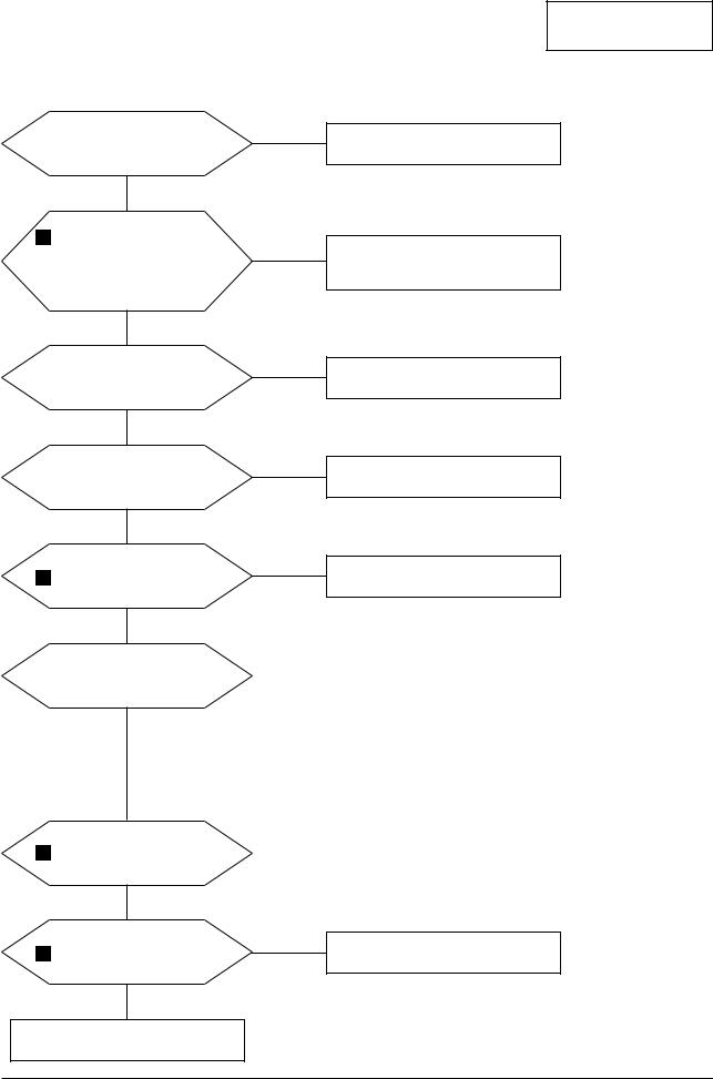
4-1-2 No Picture (RF Signal)
LED Green, Lamp on, No picture.
Check the cable connection? |
No |
|
||
(FPC, LVDS cable, IR/Tuner cable) |
|
|
||
|
|
Yes |
|
|
|
|
|
|
|
|
|
|
No |
|
|
|
|
|
|
1 |
|
|
|
|
|
|
|
|
|
|
|
|
||
No
1 Check 46th Pin of IC1?
Yes
CONFIDENTIAL
Connect the cable.
Check 33V?
(29” : BN59-00321A, IC103 7th Pin)
(40” : BN59-00323A, IC4 7th Pin)
Yes
No
2 Check Pins 11th and 12th of CN3?
Yes
Tuner board defect. Change tuner board.
(29” : BN59-00321A, 40” : BN59-00323A)
No
IIC communication error.
Change main board.
IC1 defect.
Same as CVBS.
Change main board.
|
Check 88th Pin of IC2? |
No |
FT3 defect. |
|
1 |
||||
|
Change main board. |
|||
|
|
|
||
|
|
|
|
Check 48th and 40th Pin of IC1? |
No |
IC2 defect. |
Change main board.
Check 55th and 46th Pin of IC302? |
No |
IC1 defect. |
|
|
|
Same as S-Video. |
||||
|
|
|
|
|
|
Change main board. |
|
|
|
|
|
3 |
|
4 |
|
|
|
|
|
|
|
|
|
|
Yes |
|
|
|
|
|
|
|
|
|
|
|
|
|
|
|
|
||
|
|
|
|
|
|
|
|
|
|
|
|
|
|
|
|
|
|
|
|
|
|
4-2 |
|
|
|
|
|
|
|
LT29A13W/LT40A13W |
||
4 Troubleshooting
Yes
CONFIDENTIAL
Check 9th, 17th and 23rd Pin of IC302? |
No |
Check X301. |
|
|||||||
|
|
|||||||||
|
|
|||||||||
|
|
|
|
|
|
|
|
|
|
|
|
5 |
|
6 |
|
7 |
|
|
|
|
|
|
|
|
|
|
|
|
|
|
Yes |
|
|
|
|
|
|
|
|
|
|
|
|
|
|
|
|
|
|
|
|
|
IC302 defect. |
|
No |
|
|
|
|
|
|
|
|
|
|
|
|
|
|
|
|
|
|
|
|
|
Change main board. |
|
|
|
|
|
Yes |
|
|
|
|
|
|
|
|
|
|
|
|
|
|
|
|
|
|
||
|
|
|
|
|
|
|
X301 defect. |
|
|
||
|
|
|
|
|
|
|
Change main board. |
|
|
||
Check 159th, 165th and 168th |
|
|
|
||||||||
|
|
|
|||||||||
IC703 defect. |
|
|
|||||||||
|
8 |
|
6 |
|
7 |
|
|
|
|
|
|
|
|
|
|
|
|
Change main board. |
|
|
|||
|
Pin of IC703? |
|
|
|
|
|
|
||||
|
|
|
|
|
|
|
|
||||
|
|
|
|
|
|
|
|||||
|
|
|
Yes |
|
|
|
|
|
|
|
|
|
|
|
|
|
|
|
|
|
|
||
|
|
|
|
|
|
|
|
|
|
|
|
Go to JAG ASM. |
|
|
|
|
|
|
|
||||
|
|
|
|
|
|
|
|
|
|
|
|
4-1-3 No Picture (CVBS Signal)
LED Green, Lamp on, No picture.
|
|
Check the cable connection? |
No |
Connect the cable. |
||
(FPC, LVDS cable, Component cable) |
|
|||||
|
|
|||||
|
|
|
Yes |
|
|
|
|
|
|
|
|
||
|
|
|
|
|
||
|
|
|
|
|
No |
|
|
|
|
|
|
|
|
|
|
Check 1st Pin of CN1? |
Component assy defect. |
|||
|
9 |
|
Change component assy. |
|||
|
|
|||||
|
|
|
|
|
|
|
|
|
|
|
|
|
(29” : BN59-00321A, 40” : BN59-00322A) |
|
|
|
Yes |
|
|
|
|
|
|
|
|
|
|
|
|
Same as RF. |
|
|
|
|
|
|
|
|
|
|
|
LT29A13W/LT40A13W |
4-3 |
4 Troubleshooting
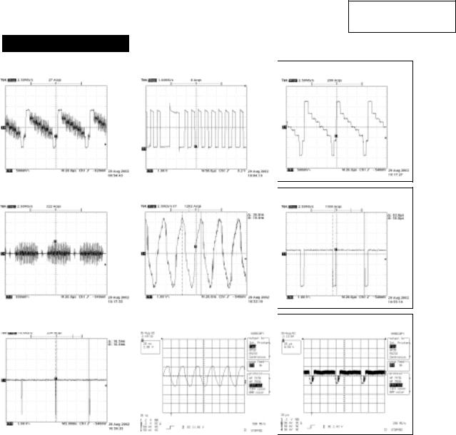
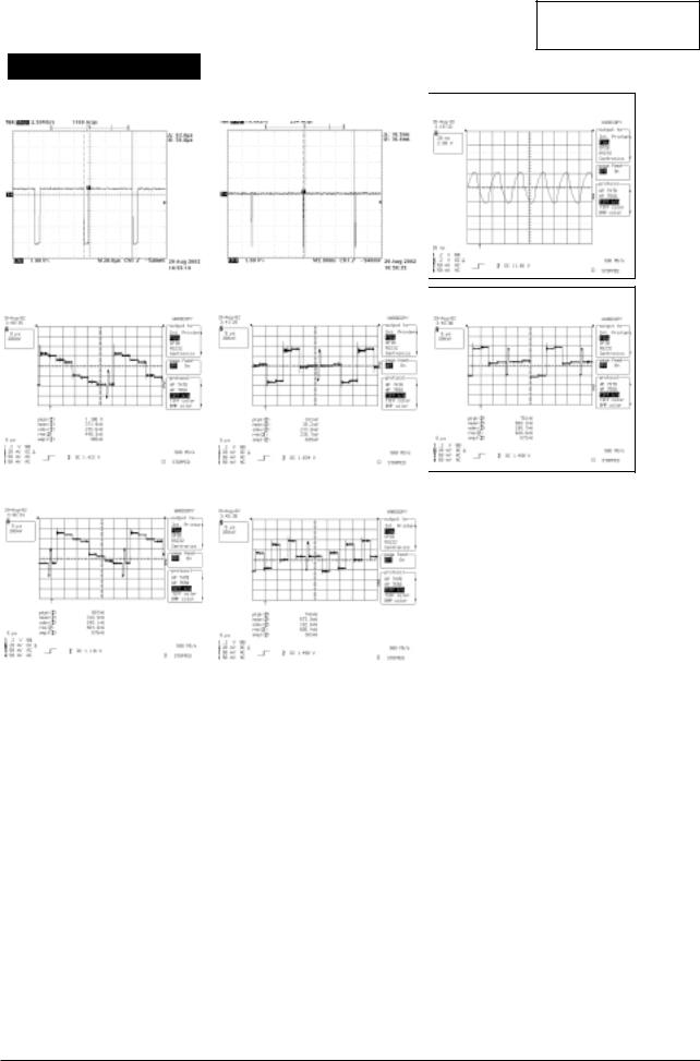
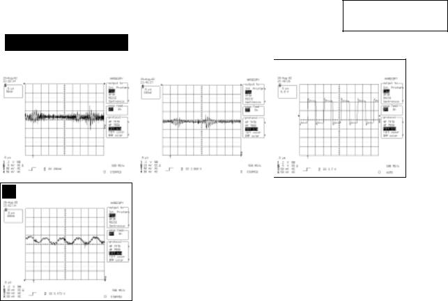
WAVEFORMS
|
|
|
|
|
|
|
|
|
|
|
|
|
1 |
|
|
|
|
2 |
|
|
|
|
3 |
|
|
|
|
|
|
|
|
|
|
|
|
|
|
|
|
|
|
|
|
|
|
|
|
|
|
|
|
|
|
|
|
|
|
|
|
|
|
|
|
|
|
|
|
|
|
|
|
|
4 |
|
|
|
|
5 |
|
|
|
|
6 |
|
|
|
|
|
|
|
|
|
|
|
|
|
|
|
|
|
|
|
|
|
|
|
|
|
|
|
|
|
|
|
|
|
|
|
|
|
|
|
|
|
|
|
|
|
|
|
|
|
7 |
|
|
|
|
8 |
|
|
|
|
9 |
|
|
|
|
|
|
|
|
|
|
|
|
|
|
|
|
|
|
|
|
|
|
|
|
|
|
|
|
|
|
|
|
|
|
|
|
CONFIDENTIAL
|
|
|
|
|
|
4-4 |
LT29A13W/LT40A13W |
|
4 Troubleshooting
4-1-4 No Picture (S-Video Signal)
LED Green, Lamp on, No picture.
CONFIDENTIAL
Check the cable connection? |
No |
Connect the cable. |
||||||
(FPC, LVDS cable, Component cable) |
|
|||||||
|
||||||||
|
|
|||||||
|
|
|
|
Yes |
|
|
||
|
|
|
|
|
|
|||
|
|
|
|
|
|
|
|
|
|
|
|
|
|
|
|
|
|
Check 4th and 6th Pin of CN1? |
No |
Component assy defect. |
||||||
Change component assy. |
||||||||
|
|
|
|
|
|
|
||
|
11 |
|
10 |
|
|
(29” : BN59-00321A, 40” : BN59-00322A) |
||
|
|
|
|
|
|
|
||
Same as RF.
WAVEFORMS
|
|
|
|
|
|
|
|
|
|
10 |
|
|
|
|
11 |
|
|
|
|
|
|
|
|
|
|
|
|
|
|
|
|
|
|
|
|
|
|
|
|
|
|
|
|
|
LT29A13W/LT40A13W |
4-5 |
4 Troubleshooting
4-1-5 No Picture (D4 Signal)
LED Green, Lamp on, No picture.
Check the cable connection? (FPC, LVDS cable, Component cable)
Yes
Check 13th, 20th,
12
9th, 11th 16th and 18th Pin of CN1?
13
Yes
Check 15th, 19th and 21st
16 |
|
15 |
|
14 |
Check 64th, 66th and 67th
7 |
|
6 |
|
8 |
Pin of IC404?
Yes
Go to JAG ASM.
CONFIDENTIAL
No
Connect the cable.
No |
Component assy defect. |
|
Change component assy. |
||
|
||
|
||
|
(29” : BN59-00321A, 40” : BN59-00322A) |
No |
IC403 defect. |
Change main board.
No |
IC404 defect. |
Change main board.
4-6 |
LT29A13W/LT40A13W |
4 Troubleshooting
WAVEFORMS
|
|
|
|
|
|
|
|
|
|
|
|
|
6 |
|
|
|
|
7 |
|
|
|
|
8 |
|
|
|
|
|
|
|
|
|
|
|
|
|
|
|
|
|
|
|
|
|
|
|
|
|
|
|
|
|
|
|
|
|
|
|
|
|
|
|
|
|
|
|
|
|
|
|
|
|
12 |
|
|
|
|
13 |
|
|
|
|
14 |
|
|
|
|
|
|
|
|
|
|
|
|
|
|
|
|
|
|
|
|
|
|
|
|
|
|
|
|
|
|
|
|
|
|
|
|
|
|
|
|
|
|
|
|
|
|
15 |
|
|
|
|
16 |
|
|
|
|
|
|
|
|
|
|
|
|
|
|
|
|
|
|
|
|
|
|
|
|
|
|
|
|
|
CONFIDENTIAL
LT29A13W/LT40A13W |
4-7 |
4 Troubleshooting
4-1-6 No Picture (PC Analog)
LED Green, Lamp on, No picture.
Check the cable connection? (FPC, LVDS cable, DVI cable)
Yes
Check 22rd and 24th Pin of CN201?
18 17
Yes
Check 30th, 31st and 67th
17 |
|
18 |
|
19 |
Check R808, R809,
23 22
R810 and R811 output of IC603?
20 21
Yes
Go to JAG ASM.
CONFIDENTIAL
No
Connect the cable.
No |
Component assy defect. |
|
Change component assy. |
||
|
||
|
||
|
(29” : BN59-00321A , 40” : BN59-00322A) |
No |
IC203 defect. |
Change main board.
No |
IC603 defect. |
Change main board.
4-8 |
LT29A13W/LT40A13W |
4 Troubleshooting
WAVEFORMS
|
|
|
|
|
|
|
|
|
|
|
|
|
17 |
|
|
|
|
18 |
|
|
|
|
19 |
|
|
|
|
|
|
|
|
|
|
|
|
|
|
|
|
|
|
|
|
|
|
|
|
|
|
|
|
|
|
|
|
|
|
|
|
|
|
|
|
|
|
|
|
|
|
|
|
|
20 |
|
|
|
|
21 |
|
|
|
|
22 |
|
|
|
|
|
|
|
|
|
|
|
|
|
|
|
|
|
|
|
|
|
|
|
|
|
|
|
|
|
|
|
|
|
|
|
|
23
CONFIDENTIAL
|
|
|
|
|
|
LT29A13W/LT40A13W |
4-9 |
|
4 Troubleshooting
4-1-7 No Picture (PC Digital)
LED Green, Lamp on, No picture.
Check the cable connection? (FPC, LVDS cable, DVI cable)
Yes
Check 1st, 2nd, 4th, 5th, 7th, 8th, 10th and 11th Pin of CN201?
Yes
Check 44th, 46th, 47th
24 27 26
and 48th Pin of IC204?
25
Check R808, R809,
23 22
R810 and R811 output of IC603?
20 21
Yes
Go to JAG ASM.
CONFIDENTIAL
No
Connect the cable.
No |
Component assy defect. |
|
Change component assy. |
||
|
||
|
||
|
(29” : BN59-00321A , 40” : BN59-00322A) |
No |
IC204 defect. |
Change main board.
No |
IC603 defect. |
Change main board.
4-10 |
LT29A13W/LT40A13W |
4 Troubleshooting
WAVEFORMS
|
|
|
|
|
|
|
|
|
|
|
|
|
20 |
|
|
|
|
21 |
|
|
|
|
22 |
|
|
|
|
|
|
|
|
|
|
|
|
|
|
|
|
|
|
|
|
|
|
|
|
|
|
|
|
|
|
|
|
|
|
|
|
|
|
|
|
|
|
|
|
|
|
|
|
|
23 |
|
|
|
|
24 |
|
|
|
|
25 |
|
|
|
|
|
|
|
|
|
|
|
|
|
|
|
|
|
|
|
|
|
|
|
|
|
|
|
|
|
|
|
|
|
|
|
|
|
|
|
|
|
|
|
|
|
|
26 |
|
|
|
|
27 |
|
|
|
|
|
|
|
|
|
|
|
|
|
|
|
|
|
|
|
|
|
|
|
|
|
|
|
|
|
CONFIDENTIAL
LT29A13W/LT40A13W |
4-11 |

4 Troubleshooting
4-2 JAG ASM
JAG ASM.
Yes
Check R812, R813,
28 29
and R814 output of IC801?
30
Yes
Check R303, R304,
28 29
and R302 output of IC603?
30
Check R307, R309, R311 and R313
31 33 32
output of IC201-1(BN41-00203A)?
34
Check 3.3V at R702 of IC700 and R730 output of IC701?
Check clock 10th, 11th, 22rd, 23rd Pin of CN701?
Panel defect.
CONFIDENTIAL
No |
IC801 defect. |
Change main board.
No |
FPC defect. |
Change main board.
No |
RTA IC201 defect. |
Change RTA board. (BN94-00372A)
No |
IC603 defect. |
Change main board.
No |
RTA IC700, 701 defect. |
|
Change RTA board. |
|
|
4-12 |
LT29A13W/LT40A13W |

4 Troubleshooting
WAVEFORMS
|
|
|
|
|
|
|
|
|
|
|
|
|
28 |
|
|
|
|
29 |
|
|
|
|
30 |
|
|
|
|
|
|
|
|
|
|
|
|
|
|
|
|
|
|
|
|
|
|
|
|
|
|
|
|
|
|
|
|
|
|
|
|
|
|
|
|
|
|
|
|
|
|
|
|
|
31 |
|
|
|
|
32 |
|
|
|
|
33 |
|
|
|
|
|
|
|
|
|
|
|
|
|
|
|
|
|
|
|
|
|
|
|
|
|
|
|
|
|
|
|
|
|
|
|
|
34
CONFIDENTIAL
|
|
|
|
|
|
LT29A13W/LT40A13W |
4-13 |
|
4 Troubleshooting
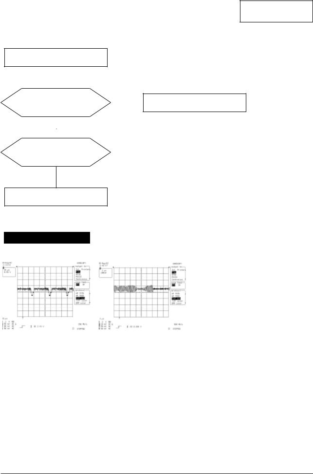
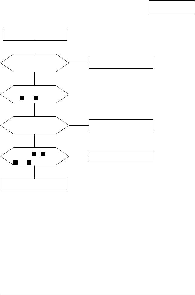
4-3 No Sound
Check the cable connection?
Yes
Sound Input?
35 RF : CN3, 14th, 16th Pin
CVBS, S-Video : CN1, 23rd, 24th Pin
D1 Input : CN1, 26th, 27th Pin
D2 Input : CN1, 29th, 30th Pin
Yes
Check 8V at 3rd Pin of IC501?
Yes
Check 5V at 3rd Pin of IC502?
Yes
36 Check 9th, 12th Pin of IC504?
Yes
Check 0V at 16th Pin of IC504?
Yes
37
Check 20th, 22th,
23rd and 25th Pin of IC504?
Check 1st, 2nd,
38
4th and 5th Pin of CN501?
Yes
Audio assy defect.
Change audio assy.
CONFIDENTIAL
No
Connect the cable.
No |
Auto assy defect. |
Change audio assy.
(29” : BN59-00320A, 40” : BN59-00322A)
No |
IC501 defect. |
Change main board.
No |
IC502 defect. |
Change main board.
No |
IC503 defect. |
Change main board.
No |
Check the connection of headphone. |
|
|
|
|
|
|
||
|
|
|
|
|
|
|
Yes |
|
|
|
|
|
|
No |
|
Disconnect headphone. |
|
||
|
|
|
|
|
|
|
|
|
|
|
Audio assy defect. |
|
|
|
|
Change audio assy. |
|
|
|
|
|
|
||
|
(29” : BN59-00320A, 40” : BN59-00322A) |
|
|
|
No |
|
|
|
|
IC504 defect. |
|
|
||
|
Change main board. |
|
|
|
|
|
|
|
|
L502, L503, L504 and L505 defect.
Change main board.
4-14 |
LT29A13W/LT40A13W |
4 Troubleshooting
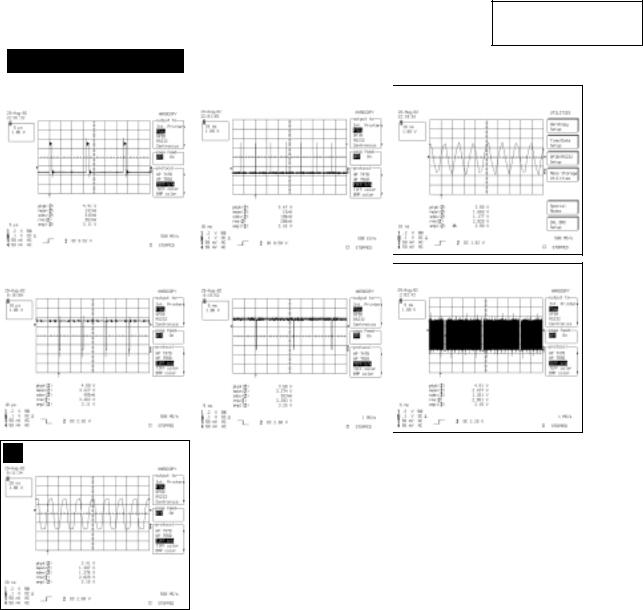
WAVEFORMS
|
|
|
|
|
|
|
|
|
|
|
|
|
35 |
|
|
|
|
36 |
|
|
|
|
37 |
|
|
|
|
|
|
|
|
|
|
|
|
|
|
|
|
|
|
|
|
|
|
|
|
|
|
|
|
|
|
|
|
|
|
|
|
38
CONFIDENTIAL
|
|
|
|
|
|
LT29A13W/LT40A13W |
4-15 |
|

4 Troubleshooting
Memo
CONFIDENTIAL
4-16 |
LT29A13W/LT40A13W |
CONFIDENTIAL
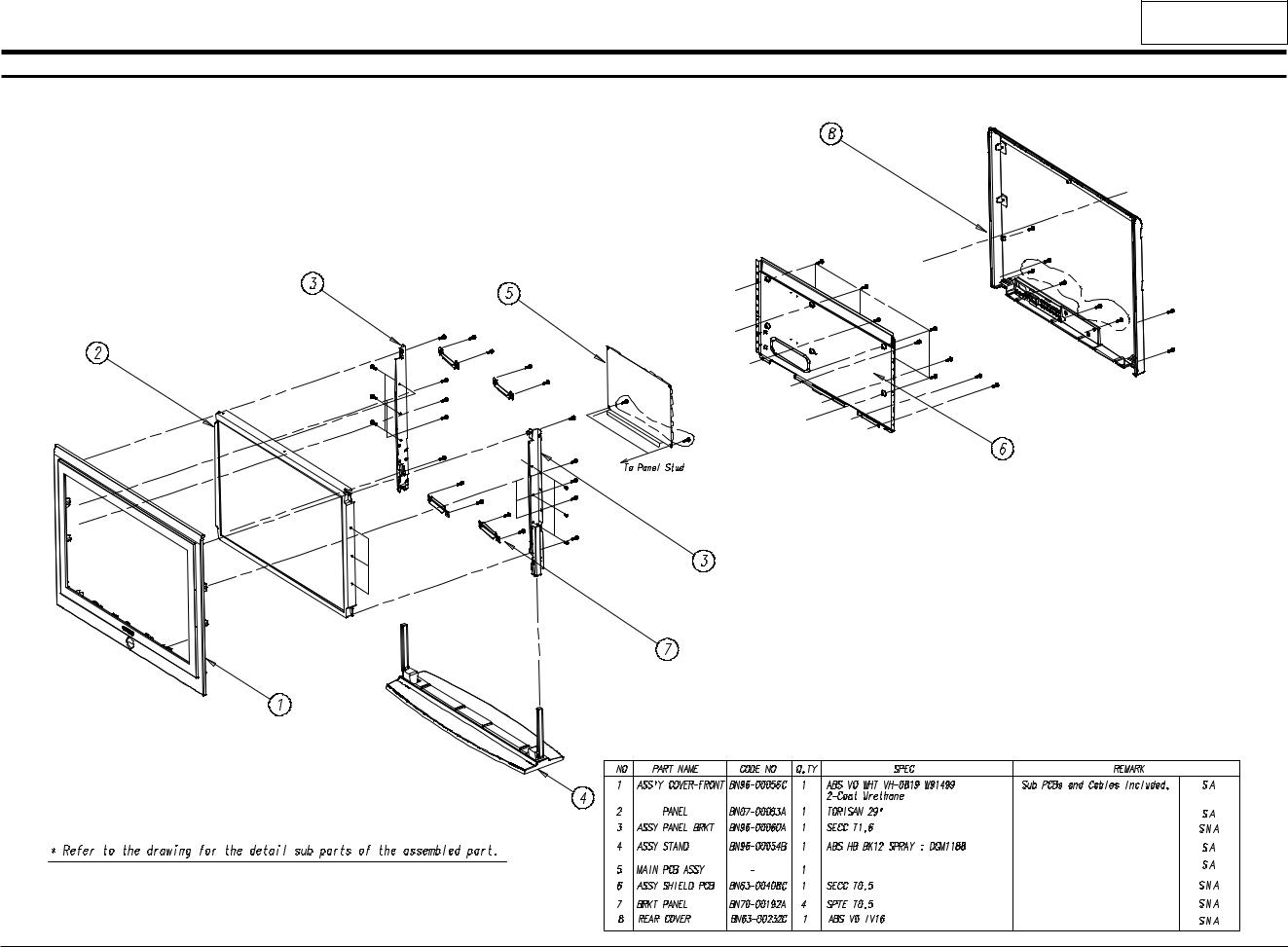
5 Exploded View and Parts List
5-1 LT29A13W
LT29A13W/LT40A13W |
5-1 |

5 Exploded View & Parts List
CONFIDENTIAL
5-2 LT40A13W
5-2 |
LT29A13W/LT40A13W |

CONFIDENTIAL
6 Electrical Parts List
6-1-1 LT29A13W Main PCB Parts
Loc. No. |
Code No. |
Description |
Specification |
Remarks |
|
|
|
|
|
- |
BN94-00362A |
ASSY PCB MAIN |
AL29JO |
SNA |
CIS01 |
6001-000677 |
SCREW-MACHINE |
RH,+,M3,L6,ZPC(YEL),SM20C,- |
SNA |
CIS04 |
0202-001044 |
SOLDER-WIRE. |
S63S-W3.0,S63S,D3,63Sn/37Pb,- |
SNA |
CIS05 |
0202-001162 |
SOLDER-CREAM |
RMA-20-21L,S63,-,SN63/PB36.6/AG0.4,FLUX9.5% |
SNA |
CIS06 |
0202-001172 |
SOLDER-WIRE FLUX |
RS-107,RS60,D1.2,SN60/PB40,- |
SNA |
CIS07 |
0204-001096 |
ETHANOL |
ISO-PROPYLENE,C2H50H,99.8%,- |
SNA |
CIS08 |
0204-001527 |
FLUX |
DF-201TVS,MIX,0.820,FLUX 13%, 14KG |
SNA |
CIS99 |
BN73-00025A |
RUBBER CUSHION |
AL29NO,CR,10*15,60,T4,BLACK,3M #9448 |
SNA |
CN2 |
3711-004261 |
CONNECTOR-HEADER |
BOX,12P,1R,2MM,ANGLE,SN |
SNA |
CN501 |
3711-004123 |
CONNECTOR-HEADER |
BOX,15P,1R,2mm,ANGLE,SN |
SNA |
CN950 |
3711-003846 |
CONNECTOR-HEADER |
BOX,8P,1R,2mm,ANGLE,SN |
SNA |
IC1 |
1001-001037 |
IC-RF/VI/AUDIO S/W |
TA8851CN,-,DIP,54P,600MIL,SING |
|
L901 |
BN27-00012A |
COIL CHOKE |
5UH,APPOLO,5UH,10%,0.01OHM MAX,10A,PEI3210S,1T,40X70X25MM,BK,-10CTO+85C |
|
X102 |
2801-003224 |
CRYSTAL-UNIT |
32.768KHz,20ppm,28-AAY,12.5pF, |
|
CIS02 |
BN96-00093A |
ASSY MISC P-SHIELD/D-SUB |
AL29NO,SPTE T0.5 |
SNA |
CIS03 |
BN97-00115W |
ASSY MICOM |
AL29JO |
|
IC105 |
1102-001108 |
IC-EPROM |
27C020,256Kx8Bit,PLCC,32P,495MIL,70nS,5V,10%,PLASTIC,0to+70C,100uA,CMOS,TR |
|
CIS |
BN46-00014R |
S/W MICOM-S/W |
AL29JO |
SNA |
- |
BN97-00150A |
ASSY SMD |
AL29JO |
SNA |
BD1 |
2703-001334 |
INDUCTOR-SMD |
1.5uH,10%,2x1.25x0.85mm |
|
BD2 |
2703-001334 |
INDUCTOR-SMD |
1.5uH,10%,2x1.25x0.85mm |
|
BD201 |
3301-001176 |
CORE-FERRITE BEAD |
AB,2x1.25x0.9mm,-,- |
|
BD202 |
3301-001176 |
CORE-FERRITE BEAD |
AB,2x1.25x0.9mm,-,- |
|
BD203 |
3301-001176 |
CORE-FERRITE BEAD |
AB,2x1.25x0.9mm,-,- |
|
BD3 |
2703-001334 |
INDUCTOR-SMD |
1.5uH,10%,2x1.25x0.85mm |
|
BD301 |
3301-001176 |
CORE-FERRITE BEAD |
AB,2x1.25x0.9mm,-,- |
|
BD302 |
3301-001176 |
CORE-FERRITE BEAD |
AB,2x1.25x0.9mm,-,- |
|
BD303 |
3301-001176 |
CORE-FERRITE BEAD |
AB,2x1.25x0.9mm,-,- |
|
BD304 |
3301-001176 |
CORE-FERRITE BEAD |
AB,2x1.25x0.9mm,-,- |
|
BD4 |
2703-001334 |
INDUCTOR-SMD |
1.5uH,10%,2x1.25x0.85mm |
|
BD401 |
3301-001176 |
CORE-FERRITE BEAD |
AB,2x1.25x0.9mm,-,- |
|
BD402 |
3301-001176 |
CORE-FERRITE BEAD |
AB,2x1.25x0.9mm,-,- |
|
BD403 |
3301-001176 |
CORE-FERRITE BEAD |
AB,2x1.25x0.9mm,-,- |
|
BD404 |
3301-001176 |
CORE-FERRITE BEAD |
AB,2x1.25x0.9mm,-,- |
|
BD405 |
3301-001176 |
CORE-FERRITE BEAD |
AB,2x1.25x0.9mm,-,- |
|
BD406 |
3301-001176 |
CORE-FERRITE BEAD |
AB,2x1.25x0.9mm,-,- |
|
BD407 |
3301-001176 |
CORE-FERRITE BEAD |
AB,2x1.25x0.9mm,-,- |
|
BD501 |
3301-001145 |
CORE-FERRITE BEAD |
AB,4.5x1.6x1.6mm,-,- |
SNA |
C1 |
2409-001065 |
C-ORGANIC |
82UF,20%,16V,WT,TP,8X6.9MM,- |
|
C10 |
2402-001155 |
C-AL,SMD |
47UF,20%,16V,WT,TP,6.3X5.2MM |
|
C1001 |
2402-001044 |
C-AL,SMD |
100UF,20%,25V,GP,TP,8.3X8.3X6.3MM |
|
C1002 |
2203-000257 |
C-CERAMIC,CHIP |
10nF,10%,50V,X7R,TP,1608 |
|
C1003 |
2203-000189 |
C-CERAMIC,CHIP |
100nF,+80-20%,25V,Y5V,TP,1608, |
|
C1004 |
2203-005137 |
C-CERAMIC,CHIP |
10uF,+80-20%,50V,JE,TP,5650,- |
|
C1005 |
2203-005137 |
C-CERAMIC,CHIP |
10uF,+80-20%,50V,JE,TP,5650,- |
|
C1006 |
2203-005005 |
C-CERAMIC,CHIP |
100nF,10%,16V,X7R,TP,1608 |
|
C1007 |
2203-005005 |
C-CERAMIC,CHIP |
100nF,10%,16V,X7R,TP,1608 |
|
C1008 |
2203-005005 |
C-CERAMIC,CHIP |
100nF,10%,16V,X7R,TP,1608 |
|
C1009 |
2409-001035 |
C-ORGANIC |
10uF,20%,10V,LZ,TP,5.4x4.3x4.3mm,1 |
|
C101 |
2203-000189 |
C-CERAMIC,CHIP |
100nF,+80-20%,25V,Y5V,TP,1608, |
|
C1010 |
2402-000176 |
C-AL,SMD |
10uF,20%,16V,GP,TP,4.3x4.3x5.4 |
|
C1011 |
2402-000176 |
C-AL,SMD |
10uF,20%,16V,GP,TP,4.3x4.3x5.4 |
|
C1012 |
2203-005005 |
C-CERAMIC,CHIP |
100nF,10%,16V,X7R,TP,1608 |
|
C1013 |
2203-000257 |
C-CERAMIC,CHIP |
10nF,10%,50V,X7R,TP,1608 |
|
C1014 |
2203-005065 |
C-CERAMIC,CHIP |
1000nF,+80-20%,10V,Y5V,TP,1608 |
|
C1015 |
2203-001851 |
C-CERAMIC,CHIP |
0.016nF,5%,50V,NP0,TP,1608 |
|
C1016 |
2203-001652 |
C-CERAMIC,CHIP |
470nF,+80-20%,16V,Y5V,TP,1608 |
|
C1017 |
2203-001652 |
C-CERAMIC,CHIP |
470nF,+80-20%,16V,Y5V,TP,1608 |
|
C1018 |
2203-001652 |
C-CERAMIC,CHIP |
470nF,+80-20%,16V,Y5V,TP,1608 |
|
C1019 |
2203-001652 |
C-CERAMIC,CHIP |
470nF,+80-20%,16V,Y5V,TP,1608 |
|
C102 |
2203-000189 |
C-CERAMIC,CHIP |
100nF,+80-20%,25V,Y5V,TP,1608, |
|
C1020 |
2203-001652 |
C-CERAMIC,CHIP |
470nF,+80-20%,16V,Y5V,TP,1608 |
|
C1021 |
2203-001652 |
C-CERAMIC,CHIP |
470nF,+80-20%,16V,Y5V,TP,1608 |
|
C1022 |
2203-001652 |
C-CERAMIC,CHIP |
470nF,+80-20%,16V,Y5V,TP,1608 |
|
C1023 |
2203-001652 |
C-CERAMIC,CHIP |
470nF,+80-20%,16V,Y5V,TP,1608 |
|
|
|
|
|
|
LT29A13W/LT40A13W |
6-1 |

6 Electrical Parts List
CONFIDENTIAL
Loc. No. |
Code No. |
Description |
Specification |
Remarks |
|
|
|
|
|
C1024 |
2203-001652 |
C-CERAMIC,CHIP |
470nF,+80-20%,16V,Y5V,TP,1608 |
|
C1025 |
2203-001652 |
C-CERAMIC,CHIP |
470nF,+80-20%,16V,Y5V,TP,1608 |
|
C1026 |
2203-001652 |
C-CERAMIC,CHIP |
470nF,+80-20%,16V,Y5V,TP,1608 |
|
C1027 |
2203-001652 |
C-CERAMIC,CHIP |
470nF,+80-20%,16V,Y5V,TP,1608 |
|
C1028 |
2203-001652 |
C-CERAMIC,CHIP |
470nF,+80-20%,16V,Y5V,TP,1608 |
|
C1029 |
2203-001652 |
C-CERAMIC,CHIP |
470nF,+80-20%,16V,Y5V,TP,1608 |
|
C103 |
2203-000189 |
C-CERAMIC,CHIP |
100nF,+80-20%,25V,Y5V,TP,1608, |
|
C1030 |
2203-001652 |
C-CERAMIC,CHIP |
470nF,+80-20%,16V,Y5V,TP,1608 |
|
C1031 |
2203-001652 |
C-CERAMIC,CHIP |
470nF,+80-20%,16V,Y5V,TP,1608 |
|
C104 |
2203-000189 |
C-CERAMIC,CHIP |
100nF,+80-20%,25V,Y5V,TP,1608, |
|
C105 |
2203-000189 |
C-CERAMIC,CHIP |
100nF,+80-20%,25V,Y5V,TP,1608, |
|
C106 |
2203-000189 |
C-CERAMIC,CHIP |
100nF,+80-20%,25V,Y5V,TP,1608, |
|
C107 |
2203-000815 |
C-CERAMIC,CHIP |
0.033nF,5%,50V,NP0,TP,1608 |
|
C108 |
2203-000815 |
C-CERAMIC,CHIP |
0.033nF,5%,50V,NP0,TP,1608 |
|
C109 |
2203-000189 |
C-CERAMIC,CHIP |
100nF,+80-20%,25V,Y5V,TP,1608, |
|
C11 |
2402-000170 |
C-AL,SMD |
1uF,20%,50V,GP,TP,4.3x4.3x5.4, |
|
C111 |
2203-000189 |
C-CERAMIC,CHIP |
100nF,+80-20%,25V,Y5V,TP,1608, |
|
C112 |
2203-000189 |
C-CERAMIC,CHIP |
100nF,+80-20%,25V,Y5V,TP,1608, |
|
C113 |
2203-000189 |
C-CERAMIC,CHIP |
100nF,+80-20%,25V,Y5V,TP,1608, |
|
C114 |
2203-000189 |
C-CERAMIC,CHIP |
100nF,+80-20%,25V,Y5V,TP,1608, |
|
C115 |
2203-000552 |
C-CERAMIC,CHIP |
0.02nF,5%,50V,NP0,TP,1608 |
|
C12 |
2402-000176 |
C-AL,SMD |
10uF,20%,16V,GP,TP,4.3x4.3x5.4 |
|
C13 |
2203-000440 |
C-CERAMIC,CHIP |
1nF,10%,50V,X7R,TP,1608,- |
|
C14 |
2402-000170 |
C-AL,SMD |
1uF,20%,50V,GP,TP,4.3x4.3x5.4, |
|
C15 |
2203-000236 |
C-CERAMIC,CHIP |
0.1nF,5%,50V,NP0,TP,1608 |
|
C16 |
2203-000236 |
C-CERAMIC,CHIP |
0.1nF,5%,50V,NP0,TP,1608 |
|
C17 |
2203-000189 |
C-CERAMIC,CHIP |
100nF,+80-20%,25V,Y5V,TP,1608, |
|
C18 |
2203-000189 |
C-CERAMIC,CHIP |
100nF,+80-20%,25V,Y5V,TP,1608, |
|
C19 |
2402-000209 |
C-AL,SMD |
22uF,20%,16V,WT,TP,5.3x5.3mm,1 |
|
C2 |
2203-000189 |
C-CERAMIC,CHIP |
100nF,+80-20%,25V,Y5V,TP,1608, |
|
C20 |
2402-000209 |
C-AL,SMD |
22uF,20%,16V,WT,TP,5.3x5.3mm,1 |
|
C201 |
2409-001035 |
C-ORGANIC |
10uF,20%,10V,LZ,TP,5.4x4.3x4.3mm,1 |
|
C202 |
2203-005005 |
C-CERAMIC,CHIP |
100nF,10%,16V,X7R,TP,1608 |
|
C203 |
2203-005005 |
C-CERAMIC,CHIP |
100nF,10%,16V,X7R,TP,1608 |
|
C204 |
2203-005005 |
C-CERAMIC,CHIP |
100nF,10%,16V,X7R,TP,1608 |
|
C205 |
2203-005005 |
C-CERAMIC,CHIP |
100nF,10%,16V,X7R,TP,1608 |
|
C206 |
2203-005005 |
C-CERAMIC,CHIP |
100nF,10%,16V,X7R,TP,1608 |
|
C207 |
2409-001035 |
C-ORGANIC |
10uF,20%,10V,LZ,TP,5.4x4.3x4.3mm,1 |
|
C208 |
2203-005005 |
C-CERAMIC,CHIP |
100nF,10%,16V,X7R,TP,1608 |
|
C209 |
2203-005005 |
C-CERAMIC,CHIP |
100nF,10%,16V,X7R,TP,1608 |
|
C210 |
2203-005005 |
C-CERAMIC,CHIP |
100nF,10%,16V,X7R,TP,1608 |
|
C211 |
2203-005005 |
C-CERAMIC,CHIP |
100nF,10%,16V,X7R,TP,1608 |
|
C212 |
2203-005005 |
C-CERAMIC,CHIP |
100nF,10%,16V,X7R,TP,1608 |
|
C213 |
2203-005005 |
C-CERAMIC,CHIP |
100nF,10%,16V,X7R,TP,1608 |
|
C214 |
2203-005005 |
C-CERAMIC,CHIP |
100nF,10%,16V,X7R,TP,1608 |
|
C215 |
2203-005005 |
C-CERAMIC,CHIP |
100nF,10%,16V,X7R,TP,1608 |
|
C216 |
2203-005005 |
C-CERAMIC,CHIP |
100nF,10%,16V,X7R,TP,1608 |
|
C217 |
2203-000189 |
C-CERAMIC,CHIP |
100nF,+80-20%,25V,Y5V,TP,1608, |
|
C218 |
2203-000189 |
C-CERAMIC,CHIP |
100nF,+80-20%,25V,Y5V,TP,1608, |
|
C219 |
2402-000176 |
C-AL,SMD |
10uF,20%,16V,GP,TP,4.3x4.3x5.4 |
|
C22 |
2203-000257 |
C-CERAMIC,CHIP |
10nF,10%,50V,X7R,TP,1608 |
|
C220 |
2203-005005 |
C-CERAMIC,CHIP |
100nF,10%,16V,X7R,TP,1608 |
|
C221 |
2203-005005 |
C-CERAMIC,CHIP |
100nF,10%,16V,X7R,TP,1608 |
|
C222 |
2203-005005 |
C-CERAMIC,CHIP |
100nF,10%,16V,X7R,TP,1608 |
|
C223 |
2203-005005 |
C-CERAMIC,CHIP |
100nF,10%,16V,X7R,TP,1608 |
|
C224 |
2203-005005 |
C-CERAMIC,CHIP |
100nF,10%,16V,X7R,TP,1608 |
|
C225 |
2402-000108 |
C-AL,SMD |
10uF,20%,16V,WT,TP,4.3x4.3x5.4 |
|
C226 |
2203-000440 |
C-CERAMIC,CHIP |
1nF,10%,50V,X7R,TP,1608,- |
|
C227 |
2203-000440 |
C-CERAMIC,CHIP |
1nF,10%,50V,X7R,TP,1608,- |
|
C228 |
2203-000384 |
C-CERAMIC,CHIP |
0.015nF,5%,50V,NP0,TP,1608 |
|
C229 |
2203-005005 |
C-CERAMIC,CHIP |
100nF,10%,16V,X7R,TP,1608 |
|
C23 |
2203-000189 |
C-CERAMIC,CHIP |
100nF,+80-20%,25V,Y5V,TP,1608, |
|
C230 |
2203-000440 |
C-CERAMIC,CHIP |
1nF,10%,50V,X7R,TP,1608,- |
|
C231 |
2203-005005 |
C-CERAMIC,CHIP |
100nF,10%,16V,X7R,TP,1608 |
|
C232 |
2203-000843 |
C-CERAMIC,CHIP |
39nF,10%,25V,X7R,TP,1608,- |
|
C233 |
2203-000726 |
C-CERAMIC,CHIP |
3.9nF,10%,50V,X7R,TP,1608,- |
|
C234 |
2203-000972 |
C-CERAMIC,CHIP |
47nF,10%,16V,X7R,TP,1608 |
|
C235 |
2203-000972 |
C-CERAMIC,CHIP |
47nF,10%,16V,X7R,TP,1608 |
|
C236 |
2203-000972 |
C-CERAMIC,CHIP |
47nF,10%,16V,X7R,TP,1608 |
|
C237 |
2402-000176 |
C-AL,SMD |
10uF,20%,16V,GP,TP,4.3x4.3x5.4 |
|
C238 |
2203-005005 |
C-CERAMIC,CHIP |
100nF,10%,16V,X7R,TP,1608 |
|
|
|
|
|
|
6-2 |
LT29A13W/LT40A13W |
 Loading...