


 Loading...
LED Monitor
Chassis : WVN2
Model : T19C300**
Chassis : WFB2
Model : T22C300**
T24C300**
SERVICE Manual 
LED Monitor |
|
Contents |
|
|
|
1. Precautions
2. Product specifications
3. Disassembly and Reassembly
4. Troubleshooting
5. Wiring Diagram
LT**C300**
|
|
|
Contents |
1. Precautions.................................................................................................................... |
1-1 |
||
1-1. |
Safety Precautions............................................................................................................... |
1-1 |
|
1-1-1. Warnings........................................................................................................................ |
1-1 |
||
1-1-2. |
Servicing the LED Monitor............................................................................................. |
1-1 |
|
1-1-3. |
Fire and Shock Hazard.................................................................................................. |
1-1 |
|
1-1-4. |
Product Safety Notices.................................................................................................. |
1-1 |
|
1-2. |
Servicing Precautions.......................................................................................................... |
1-2 |
|
1-2-1. |
General Servicing Precautions...................................................................................... |
1-2 |
|
1-3. |
Static Electricity Precautions................................................................................................ |
1-3 |
|
1-4. |
Installation Precautions........................................................................................................ |
1-4 |
|
2. Product specifications.................................................................................................. |
2-1 |
||
2-1. |
Model Comparison............................................................................................................... |
2-1 |
|
2-2. |
Feature & Specifications...................................................................................................... |
2-2 |
|
2-2-1. |
Feature.......................................................................................................................... |
2-2 |
|
2-2-2. |
Specifications................................................................................................................ |
2-3 |
|
2-3. |
Specification Comparison to Old Models............................................................................. |
2-6 |
|
2-4. |
Detail Factory Option........................................................................................................... |
2-7 |
|
2-5. Accessories.......................................................................................................................... |
2-8 |
||
3. Disassembly and Reassembly..................................................................................... |
3-1 |
3-1. Disassembly and Reassembly............................................................................................. |
3-1 |
4. Troubleshooting............................................................................................................ |
4-1 |
4-1. Previous check..................................................................................................................... |
4-1 |
4-2. How to check fault symptom................................................................................................ |
4-2 |
4-2-1. No Power....................................................................................................................... |
4-2 |
4-2-2. No video (Analog PC signal)......................................................................................... |
4-4 |
4-2-3. No video (HDMI1 - Digital signal).................................................................................. |
4-7 |
4-2-4. No video (Tuner_CVBS).............................................................................................. |
4-10 |
4-2-5. No video (Tuner DTV).................................................................................................. |
4-14 |
4-2-6. No video (Video CVBS)............................................................................................... |
4-18 |
4-2-7. No video (Component)................................................................................................ |
4-22 |
4-2-8. No sound..................................................................................................................... |
4-25 |
4-4. Adjustment......................................................................................................................... |
4-28 |
4-4-1. Service Instruction....................................................................................................... |
4-28 |
4-4-2. How to Access Service Mode...................................................................................... |
4-28 |
4-4-3. Service Mode Menu..................................................................................................... |
4-29 |
4-4-4. White Balance - Calibration......................................................................................... |
4-41 |
4-4-5. White Balance - Adjustment........................................................................................ |
4-43 |
4-5. Software Upgrade.............................................................................................................. |
4-45 |
4-5-1. How to check the SW version...................................................................................... |
4-45 |
4-5-2. How to Upgade SW and Micom.................................................................................. |
4-47 |
5. Wiring Diagram.............................................................................................................. |
5-1 |
5-1. Wiring Diagram.................................................................................................................... |
5-1 |
5-2. Board Connection................................................................................................................ |
5-2 |
5-3. Connector Functions............................................................................................................ |
5-4 |
5-4. Cables.................................................................................................................................. |
5-4 |
A. Exploded View & Part List [TC300]............................................................................ |
A-1 |
A-1. Exploded View.................................................................................................................... |
A-1 |
A-1-1. Parts List (T19C300**)................................................................................................. |
A-2 |
A-1-2. Electrical Parts List (T19C300**).................................................................................. |
A-2 |
|
A-2-1. |
Parts List (T22C300**)................................................................................................. |
A-5 |
A-2-2. |
Electrical Parts List (T22C300**).................................................................................. |
A-5 |
A-3-1. |
Parts List (T24C300**)................................................................................................. |
A-8 |
A-3-2. |
Electrical Parts List (T24C300**).................................................................................. |
A-8 |

This Service Manual is a property of Samsung Electronics Co.,Ltd.
Any unauthorized use of Manual can be punished under applicable International and/or domestic law.
© 2013 Samsung Electronics Co.,Ltd. All rights reserved.
Printed in Korea

3. Disassembly and Reassemble
3. Disassembly and Reassembly
This section of the service manual describes the disassembly and reassembly procedures for the Monitor.
As this monitor has parts that are sensitive to static electricity, be careful when handling them.
WARNING
3-1. Disassembly and Reassembly
1.Turn the monitor off before beginning the disassembly process.
2.When disassembling the monitor, do not use any metal tools except for the provided jig.
CAUTION 3. Disassemble the monitor carefully as directed in the following procedures.
|
Description |
Inch |
Picture Description |
Screws |
|
|
|
|
|
1 |
Place monitor face down on |
|
|
|
cushioned table. |
|
|
|
All
2 |
stand.Remove single screw from the |
All
3-1

3. Disassembly and Reassemble
|
Description |
Inch |
Picture Description |
Screws |
|
|
|
|
|
3 |
cover.Remove 4 screws from the rear- |
|
|
|
|
|
21.5" |
|
|
|
|
24" |
|
6003-001086 |
Remove 3 screws from the rearcover.
18.5"
4 |
Remove the one screw in |
interface area. |
18.5" |
6003-001782 |
21.5" |
|
24" |
|
3-2

3. Disassembly and Reassemble
|
|
Description |
Inch |
Picture Description |
Screws |
|
|
|
|
|
|
5 |
Detach the front from monitor. |
|
|
|
|
|
: locking point (14 point) |
|
|
|
|
|
|
|
|
||
All
6 |
Lift up the rear-cover. |
All
7 |
Remove the 4 screws of main |
board and 3 screws SMPS |
board.
6003-000115
All
3-3

3. Disassembly and Reassemble
|
Description |
Inch |
Picture Description |
Screws |
|
|
|
|
|
8 |
speaker.Remove the left and right |
|
|
|
|
|
All |
|
|
9 Remove the panel bracket.
All
10 Lift up the panel bracket.
All
11 |
Lift up the panel. |
|
|
: locking point |
|
|
||
All
3-4

3. Disassembly and Reassemble
How to disassembly Function & IR ASSY
Description |
Inch |
Picture Description |
Screws |
1 |
There is no clip. |
All |
|
||
|
|
|
|
|
|
2 |
Heat the Function Assy by Heat |
|
Gun and Lift up the Function |
|
|
|
Assy. |
|
All
 NOTE
NOTE
Reassembly procedures are in the reverse order of disassembly procedures.
3-5
1. Precautions
1. Precautions
1-1. Safety Precautions
Follow these safety, servicing and ESD precautions to prevent damage and to protect against potential hazards such as electrical shock.
1-1-1. Warnings
For continued safety, do not attempt to modify the circuit board.
WARNING |
Disconnect the AC power and DC power jack before servicing. |
|
1-1-2. Servicing the LED Monitor
1.When servicing the LED Monitor, Disconnect the AC line cord from the AC outlet.
2.It is essential that service technicians have an accurate voltage meter available at all times. Check the calibration of this meter periodically.
1-1-3. Fire and Shock Hazard
Before returning the monitor to the user, perform the following safety checks:
1.Inspect each lead dress to make certain that the leads are not pinched or that hardware is not lodged between the chassis and other metal parts in the monitor.
2.Inspect all protective devices such as nonmetallic control knobs, insulating materials, cabinet backs, adjustment and compartment covers or shields, isolation resistorcapacitor networks, mechanical insulators, etc.
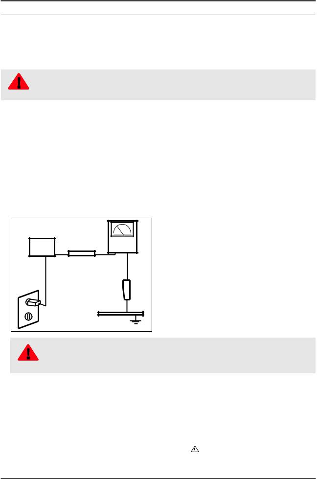
3.Leakage Current Hot Check:
(READING SHOULD) |
|
|
NOT BE ABOVE 0.5mA |
LEAKAGE |
|
DEVICE |
||
CURRENT |
||
UNDER |
||
TESTER |
||
TEST |
||
|
||
TEST ALL |
|
|
EXPOSED METAL |
|
|
SURFACES |
|
|
2-WIRE CORD |
|
|
ALSO TEST WITH PLUG |
|
|
REVERSED (USING AC |
EARTH |
|
ADAPTER PLUG AS |
||
REQUIRED) |
GROUND |
Do not use an isolation transformer during this test.
|
Use a leakage current tester or a metering system that complies with American National Standards |
|
WARNING |
Institute (ANSI C101.1, Leakage Current for Appliances), and Underwriters Laboratories (UL Publication |
|
UL1410, 59.7). |
||
|
4.With the unit completely reassembled, plug the AC line cord directly into a 120V AC outlet. With the unit’s AC switch first in the ON position and then OFF, measure the current between a known earth ground (metal water pipe, conduit, etc.) and all exposed metal parts, including: metal cabinets, screwheads and control shafts.
The current measured should not exceed 0.5 milliamp.
Reverse the power-plug prongs in the AC outlet and repeat the test.
1-1-4. Product Safety Notices
Some electrical and mechanical parts have special safetyrelated characteristics which are often not evident from visual inspection. The protection they give may not be obtained by replacing them with components rated for higher voltage, wattage, etc. Parts that have special safety characteristics are identified by on schematics and parts lists. A substitute replacement that does not have the same safety characteristics as the recommended replacement part might create shock, fire and/or other hazards. Product safety is under review continuously and new instructions are issued whenever appropriate.
1-1
1. Precautions
1-2. Servicing Precautions
WARNING
CAUTION
NOTE
An electrolytic capacitor installed with the wrong polarity might explode.
Before servicing units covered by this service manual, read and follow the Safety Precautions section of this manual.
If unforeseen circumstances create conflict between the following servicing precautions and any of the safety precautions, always follow the safety precautions.
1-2-1. General Servicing Precautions
1.Always unplug the unit’s AC power cord from the AC power source and disconnect the DC Power Jack before attempting to:
(a) remove or reinstall any component or assembly, (b) disconnect PCB plugs or connectors, (c) connect a test component in parallel with an electrolytic capacitor.
2.Some components are raised above the printed circuit board for safety. An insulation tube or tape is sometimes used. The internal wiring is sometimes clamped to prevent contact with thermally hot components. Reinstall all such elements to their original position.
3.After servicing, always check that the screws, components and wiring have been correctly reinstalled. Make sure that the area around the serviced part has not been damaged.
4.Check the insulation between the blades of the AC plug and accessible conductive parts (examples: metal panels, input terminals and earphone jacks).
5.Insulation Checking Procedure: Disconnect the power cord from the AC source and turn the power switch ON. Connect an insulation resistance meter (500 V) to theblades of the AC plug.
The insulation resistance between each blade of the AC plug and accessible conductive parts (see above) should be greater than 1 megohm.
6.Always connect a test instrument’s ground lead to the instrument chassis ground before connecting the positive lead; always remove the instrument’s ground lead last.
1-2

1. Precautions
1-3. Static Electricity Precautions
Some semiconductor (solid state) devices can be easily damaged by static electricity. Such components are commonly called Electrostatically Sensitive Devices (ESD). Examples of typical ESD are integrated circuits and some field-effect transistors. The following techniques will reduce the incidence of component damage caused by static electricity.
1.Immediately before handling any semiconductor components or assemblies, drain the electrostatic charge from your body by touching a known earth ground. Alternatively, wear a discharging wrist-strap device. To avoid a shock hazard, be sure to remove the wrist strap before applying power to the monitor.
2.After removing an ESD-equipped assembly, place it on a conductive surface such as aluminum foil to prevent accumulation of an electrostatic charge.
3.Do not use freon-propelled chemicals. These can generate electrical charges sufficient to damage ESDs.
4.Use only a grounded-tip soldering iron to solder or desolder ESDs.
5.Use only an anti-static solder removal device. Some solder removal devices not classified as “anti-static” can generate electrical charges sufficient to damage ESDs.
6.Do not remove a replacement ESD from its protective package until you are ready to install it. Most replacement ESDs are packaged with leads that are electrically shorted together by conductive foam, aluminum foil or other conductive materials.
7.Immediately before removing the protective material from the leads of a replacement ESD, touch the protective material to the chassis or circuit assembly into which the device will be installed.
Be sure no power is applied to the chassis or circuit and observe all other safety precautions.
CAUTION
8.Minimize body motions when handling unpackaged replacement ESDs. Motions such as brushing clothes together, or lifting your foot from a carpeted floor can generate enough static electricity to damage an ESD.
1-3

1. Precautions
1-4. Installation Precautions
1.For safety reasons, more than a people are required for carrying the product.
2.Keep the power cord away from any heat emitting devices, as a melted covering may cause fire or electric shock.
3.Do not place the product in areas with poor ventilation such as a bookshelf or closet. The increased internal temperature may cause fire.
4.Bend the external antenna cable when connecting it to the product. This is a measure to protect it from being exposed to moisture. Otherwise, it may cause a fire or electric shock.
5.Make sure to turn the power off and unplug the power cord from the outlet before repositioning the product. Also check the antenna cable or the external connectors if they are fully unplugged. Damage to the cord may cause fire or electric shock.
6.Keep the antenna far away from any high-voltage cables and install it firmly. Contact with the highvoltage cable or the antenna falling over may cause fire or electric shock.
7.When installing the product, leave enough space (0.4m) between the product and the wall for ventilation purposes.
A rise in temperature within the product may cause fire.
8.If an equipment is provided with a replaceable battery, and if replacement by an incorrect type could result in an explosion (for example, with some lithium batteries), the following applies:
RISK OF EXPLOSION IF BATTERY IS REPLACED BY AN INCORRECT TYPE.
CAUTION |
DISPOSE OF USED BATTERIES ACCORDING TO THE INSTRUCTIONS. |
|
1-4

2. Product specifications
2. Product specifications
2-1. Model Comparison
TC300
Front View
Detail View
Front Color |
Semitransparent Rose Black |
|
|
Panel Type |
TN |
|
|
Internal Memory |
None |
|
|
DDR |
256 Mbtye |
|
|
Feature |
Media Play(MOVIE) |
2-1

2. Product specifications
2-2. Feature & Specifications
2-2-1. Feature
•RF, 1-HDMI, 1-Component, 1-A/V, 1-USB2.0, D-SUB
•Brightness: 250cd/m2
•High Contrast Ratio: 1,000
•Response Time: 5ms
•Excellent Picture Quality
•Dynamic Contrast
-- Automatically detects the input visual signal and adjusts to create optimum contrast.
•Monitor Tuner, HDMI, Stereo, SRS Trusurround support
•Convenience
-- The Monitor utilizes the HDMI system to implement perfect digital sound and picture quality.
2-2

2. Product specifications
2-2-2. Specifications
Model Name |
T19C300** |
||
|
|
|
|
|
Item |
Description |
|
|
|
|
|
LCD Panel |
|
|
19 inch HD 60Hz |
|
|
|
|
Scanning Frequency |
Horizontal: 31 kHz ~ 80 kHz (Automatic) |
||
|
|
|
Vertical: 50 Hz ~ 75 Hz (Automatic) |
|
|
|
|
Display Colors |
|
|
16.7 Million colors |
|
|
|
|
Maximum resolution |
Horizontal : 1366 Pixels |
||
|
|
|
Vertical : 768 Pixels |
|
|
|
|
Input Signal |
|
|
Analog 0.7 Vp-p ± 5% positive at 75Ω, internally terminated |
|
|
|
|
Input Sync Signal |
|
|
H/V Separate, TTL, P. or N. |
|
|
|
|
Maximum Pixel Clock rate |
85 MHz |
||
|
|
|
|
Active Display (Horizontal/Vertical) |
409.8 (H) x 230.4 (V) (mm) / 16.1 (H) x 9.1 (V) (inches) |
||
|
|
|
|
AC power voltage & Frequency |
AC 90V~240V, 60/50Hz ± 3Hz |
||
|
|
|
|
Power Consumption |
Under 35 W(Under 0.5 W, Stand by) |
||
|
|
|
|
Dimensions |
|
With Stand |
444.7 x 356.4 x 187 (mm) / 17.5 x 14.0 x 7.4 (inches) |
(WxHxD) |
|
|
|
|
Without Stand |
444.7 x 278.2 x 48.5 (mm) / 17.5 x 11.0 x 2.0 (inches) |
|
|
|
||
|
|
|
|
Weight |
|
With Stand |
3.2 (kg) / 7.05 (lbs) |
|
|
|
|
|
|
Without Stand |
3.05 (kg) / 6.72 (lbs) |
|
|
|
|
TV System |
|
Tuning |
Frequency Synthesize |
|
|
|
|
|
|
System |
NTSC, PAL |
|
|
|
|
|
|
Sound |
NTSC, PAL |
|
|
|
|
Audio Specifications |
MAX Internal Audio Output Power : Each 5W(Left/Right) |
||
|
|
|
Equalizer : 5band |
|
|
|
Output Frequency |
|
|
|
• RF : 20 Hz ~ 15.4 kHz |
|
|
|
• AV/Componet/HDMI : 20 Hz ~ 20 kHz |
|
|
|
|
Environmental |
|
Operating |
Operating Temperature : 50°F - 104°F (10°C - 40°C) |
considerations |
|
|
Humidity : 10% - 80 % |
|
|
|
|
|
|
Storage |
Storage Temperature : -4°F - 113°F (-20°C - 45°C) |
|
|
|
Humidity : 5% - 95% |
|
|
|
|
Note: Dolby Digital +, Game Mode, Film Mode, Energy Saving
2-3

2. Product specifications
Model Name |
T22C300** |
||
|
|
|
|
|
Item |
Description |
|
|
|
|
|
LCD Panel |
|
|
21.5 inch FHD 60Hz |
|
|
|
|
Scanning Frequency |
Horizontal: 31 kHz ~ 80 kHz (Automatic) |
||
|
|
|
Vertical: 50 Hz ~ 75 Hz (Automatic) |
|
|
|
|
Display Colors |
|
|
16.7 Million colors |
|
|
|
|
Maximum resolution |
Horizontal: 1920 Pixels |
||
|
|
|
Vertical: 1080 Pixels |
|
|
|
|
Input Signal |
|
|
Analog 0.7 Vp-p ± 5% positive at 75Ω, internally terminated |
|
|
|
|
Input Sync Signal |
|
|
H/V Separate, TTL, P. or N. |
|
|
|
|
Maximum Pixel Clock rate |
85 MHz |
||
|
|
|
|
Active Display (Horizontal/Vertical) |
476.6 (H) x 268.1 (V) (mm) / 18.8 (H) x 10.6 (V) (inches) |
||
|
|
|
|
AC power voltage & Frequency |
AC 90V~240V, 60/50Hz ± 3Hz |
||
|
|
|
|
Power Consumption |
Under 35 W(Under 0.5 W, Stand by) |
||
|
|
|
|
Dimensions |
|
With Stand |
509.7 x 396.6 x 195 (mm) / 20.1 x 15.6 x 7.7 (inches) |
(WxHxD) |
|
|
|
|
Without Stand |
509.7 x 318.2 x 47 (mm) / 20.1 x 12.5 x 1.9 (inches) |
|
|
|
||
|
|
|
|
Weight |
|
With Stand |
3.95 (kg) / 8.7 (lbs) |
|
|
|
|
|
|
Without Stand |
3.7 (kg) / 8.16 (lbs) |
|
|
|
|
TV System |
|
Tuning |
Frequency Synthesize |
|
|
|
|
|
|
System |
NTSC, PAL |
|
|
|
|
|
|
Sound |
NTSC, PAL |
|
|
|
|
Audio Specifications |
MAX Internal Audio Output Power : Each 5W(Left/Right) |
||
|
|
|
Equalizer : 5band |
|
|
|
Output Frequency |
|
|
|
• RF : 20 Hz ~ 15.4 kHz |
|
|
|
• AV/Componet/HDMI : 20 Hz ~ 20 kHz |
|
|
|
|
Environmental |
|
Operating |
Operating Temperature : 50°F - 104°F (10°C - 40°C) |
considerations |
|
|
Humidity : 10% - 80 % |
|
|
|
|
|
|
Storage |
Storage Temperature : -4°F - 113°F (-20°C - 45°C) |
|
|
|
Humidity : 5% - 95% |
|
|
|
|
Note: Dolby Digital +, Game Mode, Film Mode, Energy Saving
2-4

2. Product specifications
Model Name |
T24C300** |
||
|
|
|
|
|
Item |
Description |
|
|
|
|
|
LCD Panel |
|
|
24 inch FHD 60Hz |
|
|
|
|
Scanning Frequency |
Horizontal: 31 kHz ~ 80 kHz (Automatic) |
||
|
|
|
Vertical: 50 Hz ~ 75 Hz (Automatic) |
|
|
|
|
Display Colors |
|
|
16.7 Million colors |
|
|
|
|
Maximum resolution |
Horizontal: 1920 Pixels |
||
|
|
|
Vertical: 1080 Pixels |
|
|
|
|
Input Signal |
|
|
Analog 0.7 Vp-p ± 5% positive at 75Ω, internally terminated |
|
|
|
|
Input Sync Signal |
|
|
H/V Separate, TTL, P. or N. |
|
|
|
|
Maximum Pixel Clock rate |
85 MHz |
||
|
|
|
|
Active Display (Horizontal/Vertical) |
531.36 (H) x 298.89 (V) (mm) / 20.92 (H) x 11.77 (V) (inches) |
||
|
|
|
|
AC power voltage & Frequency |
AC 90V~240V, 60/50Hz ± 3Hz |
||
|
|
|
|
Power Consumption |
Under 40 W(Under 0.5 W, Stand by) |
||
|
|
|
|
Dimensions |
|
With Stand |
569.2 x 428 x 195 (mm) / 22.4 x 16.9 x 7.7 (inches) |
(WxHxD) |
|
|
|
|
Without Stand |
569.2 x 349.4 x 49 (mm) / 22.4 x 13.8 x 1.9 (inches) |
|
|
|
||
|
|
|
|
Weight |
|
With Stand |
4.45 (kg) / 9.81 (lbs) |
|
|
|
|
|
|
Without Stand |
4.15 (kg) / 9.15 (lbs) |
|
|
|
|
TV System |
|
Tuning |
Frequency Synthesize |
|
|
|
|
|
|
System |
NTSC, PAL |
|
|
|
|
|
|
Sound |
NTSC, PAL |
|
|
|
|
Audio Specifications |
MAX Internal Audio Output Power : Each 5W(Left/Right) |
||
|
|
|
Equalizer : 5band |
|
|
|
Output Frequency |
|
|
|
• RF : 20 Hz ~ 15.4 kHz |
|
|
|
• AV/Componet/HDMI : 20 Hz ~ 20 kHz |
|
|
|
|
Environmental |
|
Operating |
Operating Temperature : 50°F - 104°F (10°C - 40°C) |
considerations |
|
|
Humidity : 10% - 80 % |
|
|
|
|
|
|
Storage |
Storage Temperature : -4°F - 113°F (-20°C - 45°C) |
|
|
|
Humidity : 5% - 95% |
|
|
|
|
Note: Dolby Digital +, Game Mode, Film Mode, Energy Saving
2-5

2. Product specifications
2-3. Specification Comparison to Old Models
|
|
|
|
O : application, X : non-application |
|
|
|
|
|
Model |
|
TC300 |
TB300 / TB350 / TB530 /TB531 |
|
|
(T**C300) |
|
(T**B300 / T**B350 / T**B530/T**B531) |
|
|
|
|||
Design
Diplay Type |
|
LCD |
|
LCD |
|
|
|
|
|
Built-in Tuner |
1 |
1 |
||
|
|
|
|
|
Resolution |
|
1920 x 1080 (21.5", 24") |
|
1920 x 1080 (21.5", 23", 23.6", 24", 27") |
|
1366 x 768 (18.5") |
|
1366 x 768 (18.5") |
|
|
|
|
||
|
|
|
|
|
LCD Panel |
|
TFT LED PANEL |
|
TFT LED PANEL |
|
|
|
|
|
Screen Size |
19" / 22" / 24" |
19" / 22" / 23" / 23.6" / 24" / 27" |
||
|
|
|
|
|
Picture ratio |
16:9 |
16:9 |
||
|
|
|
|
|
Brightness |
|
250 cd/m2 |
|
250 cd/m2 |
Contrast Ratio |
1,000 |
1,000 |
||
|
|
|
|
|
Picture Enhancer |
|
HyperReal Engine (X9) |
|
HyperReal Engine (X9) |
|
|
|
|
|
Equalizer |
|
5 Band |
|
5 Band |
|
|
|
|
|
Auto Volume Control |
|
O |
|
O |
|
|
|
|
|
Surround Sound |
|
Dolby Digital Plus/Pulse |
|
Dolby Digital Plus/Pulse |
|
|
|
|
|
Speaker Output |
|
5W X 5W |
|
5W X 5W |
|
|
|
|
|
PIP |
|
O |
|
O |
|
|
|
|
|
Double Window |
|
O |
|
O |
|
|
|
|
|
Caption |
|
O |
|
O |
|
|
|
|
|
Entertainment Mode |
|
X |
|
X |
|
|
|
|
|
Game Mode |
|
O |
|
O |
|
|
|
|
|
Energy Saving |
|
O |
|
O |
|
|
|
|
|
Anynet+ |
|
X |
|
X |
|
|
|
|
|
Antenna |
|
1(Cable/Air) |
|
1(Cable/Air) |
2-6

2. Product specifications
2-4. Detail Factory Option
If you replace the main board with new one, please change the factory option as well. The options you must change are “Type”
TC300
|
Model Name |
T19C300** |
T22C300** |
T24C300** |
||
|
|
|
|
|
|
|
|
|
|
Vendor |
AML |
CMI |
AUO |
|
|
|
|
|
|
|
Panel |
|
CODE |
BN07-01043A |
BN07-01076A |
BN07-00929A |
|
|
|
|
|
|
|
|
|
|
|
SPEC |
LTM185AT05-V |
M215HGE-L21 |
M240HW01-VB |
|
|
|
|
|
|
|
SMPS |
|
PD Board |
BN44-00504A |
BN44-00505A |
BN44-00505A |
|
|
|
|
|
|
|
|
Byte |
|
|
Item |
|
|
|
|
|
|
|
|
|
|
0 |
|
Factory Reset |
|
|
|
|
|
|
|
|
|
|
|
1 |
|
|
Type |
19A6TH1E |
22D6TF0E |
24L6TF0E |
|
|
|
|
|
|
|
2 |
|
Local Set |
|
EU |
|
|
|
|
|
|
|
|
|
3 |
|
|
Model |
|
TC300 |
|
|
|
|
|
|
|
|
4 |
|
SVC Model |
|
300 |
|
|
|
|
|
|
|
||
4 |
|
|
Tuner |
AUTO/SI_ATC2/SEC_TC/SEC_ISDB/DVB_TCS2/ |
||
|
|
DVB_T2C/DVB_T2CS2/ECHO_CD/NO_TUNER |
||||
|
|
|
|
|||
|
|
|
|
|
|
|
5 |
|
Ch Table |
|
NONE |
|
|
|
|
|
|
|
|
|
6 |
|
Front Color |
|
NONE |
|
|
|
|
|
|
|
|
|
2-7
2. Product specifications
2-5. Accessories |
|
|
|
Product |
Description |
Code. No |
Remark |
|
Remote Control & |
AA59-00622A |
|
|
Batteries |
|
|
|
4301-000121 |
|
|
|
(AAA x 2) |
|
|
|
|
|
|
|
Quick Setup Guide |
BN68-04796A |
|
|
Cloth clean |
BN63-01798B |
|
|
Owners Manual |
BN46-00319A |
|
|
|
|
Samsung Electronics |
|
|
|
Service Center |
|
|
|
(The part code for some |
|
Power Cord |
3903-000525 |
accessories may differ |
|
depending on your |
||
|
|
|
|
|
|
|
region.) |
|
D-Sub Cable |
BN39-00244H |
|
|
Stereo Cable |
BN39-01286A |
|
|
Stand Base |
- |
|
|
Stand Body & Screw |
- |
|
|
(1EA) |
|
|
|
|
|
|
2-8 |
|
|
|
4. Troubleshooting
4. Troubleshooting
4-1. Previous check
1.Check the various cable connections first.
-- Check to see if there is a burnt or damaged cable.
-- Check to see if there is a disconnected or loose cable connection.
-- Check to see if the cables are connected according to the connection diagram.
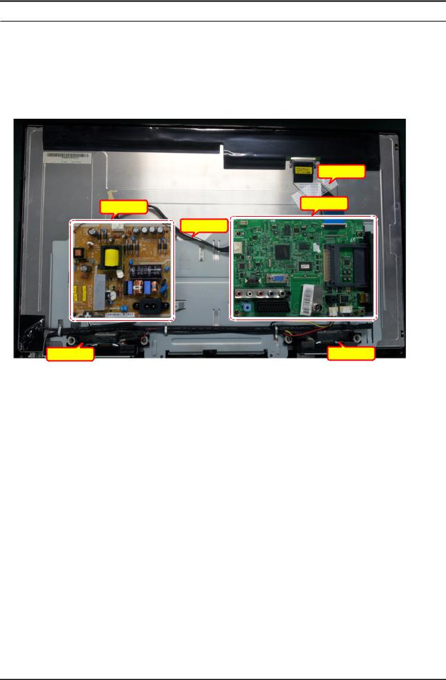
2.Check the power input to the Main Board.
|
LVDS Cable |
SMPS Assy |
Main Assy |
|
|
|
14P Cable |
Speaker |
Speaker |
Main Assy
1 |
B5V |
8 |
GND |
2 |
SW_POWER |
9 |
B12VS |
3 |
B5V |
10 |
SW_INVERTER |
|
|
|
|
4 |
A5V |
11 |
B13V |
5 |
GND |
12 |
NC |
6 |
GND |
13 |
B13V |
7 |
B12VS |
14 |
PWM_DIMM |
SMPS Assy
1 |
B13V |
8 |
PWM_DIMM |
2 |
B13V |
9 |
NC |
3 |
Vamp |
10 |
BLU_ON |
4 |
Vamp |
11 |
GND |
5 |
GND |
12 |
GND |
6 |
B5V |
13 |
A5V |
7 |
B5V |
14 |
PS_ON |
4-1
4. Troubleshooting
4-2. How to check fault symptom
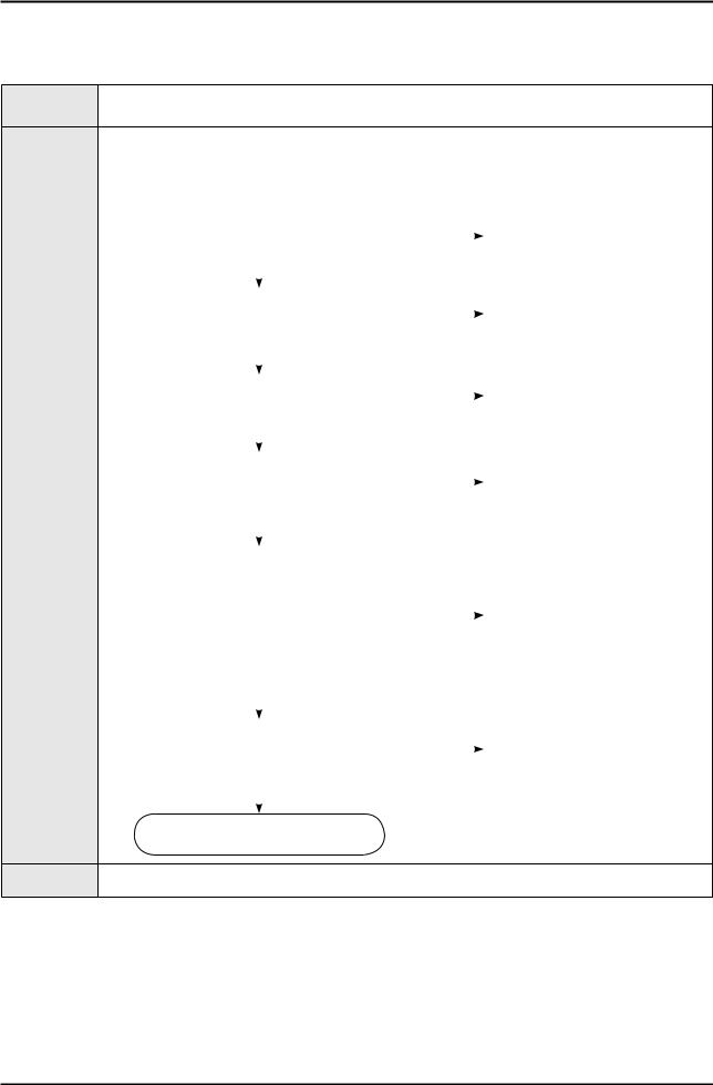
4-2-1. No Power
Symptom |
The LED on the front panel of the monitor does not work when the power is connected and the Power |
|
button is pressed. |
||
|
•Check if the Power switch on the rear panel of the monitor has been turned on.
Major |
• Check the SMPS fuse and output power of power adapter. |
|
|
||||||||
checkpoints |
• Check the power part of the Main Board and check if a similar symptom appears at another output |
||||||||||
|
terminal. |
|
|
|
|
|
|
||||
|
|
|
|
|
|
|
|
|
|
|
|
|
|
|
|
|
|
|
|
|
|
|
|
|
|
Power indicator LED on? |
|
|
|
|
Check an AC power connection. |
|
|||
|
|
|
No |
|
|
|
|||||
|
|
|
|
|
|||||||
|
|
|
|
|
|
|
|
|
|
|
|
|
|
|
|
|
|
|
|
|
|
|
|
|
|
|
Yes |
|
|
|
|
|
|
|
|
|
|
|
|
|
|
|
|
|
|
|
|
|
|
|
|
|
|
|
|
|
|
|
|
|
|
Check the 14P power cable. |
|
|
|
|
Change 14p power cable and |
|
|||
|
|
|
No |
|
|
|
|||||
|
|
|
|
|
SMPS. |
|
|||||
|
|
|
|
|
|
|
|
|
|
|
|
|
|
|
|
|
|
|
|
|
|
|
|
|
|
|
|
|
|
|
|
|
|
|
|
|
|
|
Yes |
|
|
|
|
|
|
|
|
|
|
|
|
|
|
|
|
|
|
|
|
|
|
|
|
|
|
|
|
|
|
|
|
|
|
Check the ‘Stand-By 5V’, DCA5V appear |
|
|
|
|
|
|
|||
|
|
|
No |
|
|
|
|
||||
|
|
at BD207? |
|
|
|
|
|
||||
|
|
|
|
|
|
|
|
||||
|
|
|
|
|
|
|
|
|
|
|
|
|
|
|
|
|
|
|
|
|
|
|
|
|
|
|
Yes |
|
|
|
|
|
Change SMPS. |
|
|
|
|
|
|
|
|
|
|
|
|
|
|
|
|
|
|
|
|
|
|
|
|
|
|
|
|
Check the ‘Power input of Main Ass’y’ ? |
|
|
|
|
|
|
|||
|
|
DC B13V, B5V appear at BD209(B13V), |
|
|
|
|
|
|
|||
|
|
|
No |
|
|
|
|
||||
|
|
|
|
|
|
||||||
|
|
BD213/208(B5V)? |
|
|
|
|
|
|
|||
|
|
|
|
|
|
|
|
|
|
|
|
|
|
|
|
|
|
|
|
|
|
|
|
Diagnostics |
|
|
Yes |
|
|
|
|
|
|
|
|
|
|
|
|
|
|
|
|
|
|
|
|
|
|
|
|
|
|
|
|
|
|
|
|
|
|
Check the ‘Power input of submicom |
|
|
|
|
|
|
|||
|
|
IC(A3.3V)’ ? |
|
|
|
|
|
|
|||
|
|
Check the ‘Power of nand flash |
|
|
|
|
|
|
|||
|
|
IC(B3.3V)’ , ‘Power of main IC(B2.5V, |
|
|
|
|
Change the Main Assy. |
|
|||
|
|
|
No |
|
|
|
|||||
|
|
B1.1V)’, ‘Power of DDR IC(B1.5V)’ |
|
|
|
|
|||||
|
|
|
|
|
|
|
|
||||
|
|
appear at IC202(#5), L201 (B3.3V), |
|
|
|
|
|
|
|||
|
|
BD1008/9/10/11 (B2.5V), BD1002 |
|
|
|
|
|
|
|||
|
|
(B1.2V), BD1012 (B1.5V)? |
|
|
|
|
|
|
|||
|
|
|
|
|
|
|
|
|
|
|
|
|
|
|
|
|
|
|
|
|
|
|
|
|
|
|
Yes |
|
|
|
|
|
|
|
|
|
|
|
|
|
|
|
|
|
|
|
|
|
|
|
|
|
|
|
|
|
|
|
|
|
|
Check ‘Power of LVDS (13V)’ appear |
|
|
|
|
Reconnect of Change the LVDS |
|
|||
|
|
at LVDS connector Pin #1~5 of T-con |
|
|
|
|
|
||||
|
|
|
No |
|
|
|
|||||
|
|
|
|
|
cable. |
|
|||||
|
|
board? |
|
|
|
|
|
||||
|
|
|
|
|
|
|
|
||||
|
|
|
|
|
|
|
|
|
|
|
|
|
|
|
|
|
|
|
|
|
|
|
|
|
|
|
Yes |
|
|
|
|
|
|
|
|
|
|
|
|
|
|
|
|
|
|
||
|
|
Please, Contact tech support. |
|
|
|
|
|
|
|||
Caution Make sure to disconnect the power before working on the SMPS board.
4-2
Loading...