


DM550-Cover(GB)-NOR 7/27/02 13:08 Page 2
DIGITAL HOME
THEATER SYSTEM
HT-DM550
Instruction Manual
COMPACT COMPACT
V I D E O |
DIGITAL AUDIO |
DIGITAL VIDEO |

DM550(GB)-noRDS 7/27/02 12:25 Page 1


 Safety Warnings
CLASS 1 LASER PRODUCT
KLASSE 1 LASER PRODUKT
LUOKAN 1 LASER LAITE
KLASS 1 LASER APPARAT
PRODUCTO LASER CLASE 1
CAUTION
RISK OF ELECTRIC SHOCK.
DO NOT OPEN
CAUTION:
TO REDUCE THE RISK OF ELECTRIC SHOCK, DO NOT REMOVE REAR COVER. NO USER SERVICEABLE PARTS INSIDE. REFER SERVICING TO QUALIFIED SERVICE PERSONNEL.
CLASS 1 LASER PRODUCT
This Compact Disc player is classified as a CLASS 1 LASER product.
performance of procedures other result in hazardous radiation
RADIATION WHEN OPEN AND INTERLOCKS DEFEATED, AVOID EXPOSURE TO BEAM.
This symbol indicates that dangerous voltage which can cause electric shock is present inside this unit.
This symbol alerts you to important operating and maintenance instructions accompanying the unit.
WARNING: To reduce the risk of fire or electric shock, do not expose this appliance to rain or moisture.
CAUTION: TO PREVENT ELECTRIC SHOCK, MATCH WIDE BLADE OF PLUG TO WIDE SLOT, FULLY INSERT.
1

DM550(GB)-noRDS 7/27/02 12:25 Page 2


 Precautions
Ensure that the AC power supply in your house complies with the identification sticker located on the back of your player. Install your player horizontally, on a suitable base (furniture), with enough space around it for ventilation (3~4inches). Make sure the ventilation slots are not covered. Do not stack anything on top of the player. Do not place the player on amplifiers or other equipment which may become hot. Before moving the player, ensure the disc tray is empty. This player is designed for continuous use. Switching off the DVD player to the stand-by mode does not disconnect the electrical supply. In order to disconnect the player completely from the power supply, remove the main plug from the wall outlet, especially when left unused for a long period of time.
During thunderstorms, disconnect the main plug from the socket.
Main voltage peaks due to lightning could damage the unit.
Protect the player from moisture(dripping or splashing and that no objects filled with liquids,such as vases, shall be placed on the player), and excess heat(e.g.fireplace) or equipment creating strong magnetic or electric fields (i.e.speakers...) disconnect the power cable from the mains electricity supply if the player malfunction. Your player is not intended for industrial use but for domestic purposes only. Use of this product is for personal use only. Condensation If your player or disc have been stored in a cold atmosphsre. as for example during transportation in the winter, wait for approximately 2 hours until they have reached room temperature.
Do not expose the unit to direct sun radiation or other heat sources.
This could lead to overheating and malfunction of the unit.
The battery used in this product contains the chemicals that are harmful to the environment.
Do not dispose of batteries in the general household waster. It is recommended that the replacement of the battery should be done by technician.
2

DM550(GB)-noRDS 7/27/02 12:25 Page 3
V I D E O
DVD (Digital Versatile Disc) offers fantastic audio and video, thanks to Dolby Digital surround sound and MPEG-2 video compression technology. Now you can enjoy these realistic effects in the home, as if you were in a movie theater or concert hall.
1 ~ 6
DVD players and the discs are coded by region. These regional codes must match in order for the disc to play. If the codes do not match, the disc will not play.
The Region Number for this player is given on the rear panel of the player.
(Your DVD player will only play DVDs that are labeled with identical region codes.)
Do not use the following types of disc!
this player.
appears on the TV screen.
appears on the TV screen.
Copy Protection
•Many DVD discs are encoded with copy protection. Because of this, you should only connect your DVD player directly to your TV, not to a VCR. Connecting to a VCR results in a distorted picture from copy-protected DVD discs.
•This product incorporates copyright protection technology that is protected by methods claims of certain U.S. patents and other intellectual property rights owned by Macrovision Corporation and other rights owners. Use of this copyright protection technology must be authorized by Macrovision Corporation, and is intended for home and other limited viewing uses only unless otherwise authorized by Macrovision Corporation. Reverse engineering or disassembly is prohibited.
3
DM550(GB)-noRDS 7/27/02 12:25 Page 4


 Contents
CHAPTER 1.
PREPARATION
Safety Warnings 
 1
1
Precautions 
 2
2
Description
 5
5
Remote Control
 7
7
Listening on headphones 
 8
8
CHAPTER 2.
CONNECTIONS
CHAPTER 4.
SETUP
Setting up the Language Features 
 28
28
System Setup
 29
29
Speaker Setup 
 31
31
To set up Speaker Balance 
 33
33
Creating Realistic Sound Fields 
 34
34
Dolby Pro Logic II decoder 
 35
35
DSP (Digital Signal Processor) Modes
 37
37
To increase Effect level 
 38
38
Adjusting DSP Sound Parameters 
 38
38
Presetting stations 
 40
40
CHAPTER 3.
OPERATION
DVD Playback 
 15
15
MP3-CD Playback 
 17
17
Forward/Reverse Searching 
 19
19
Slow Playback/Checking the Remaining Time 
 20
20
Repeat Playback 
 21
21
Using Disc Menu/Title 
 22
22
Selecting the Audio Language/Subtitle Language
 23
23
Zoom/Angle Functions
 24
24
Program Playback
 25
25
Sleep/D.R.C Function 
 27
27
MISCELLANENOUS OPERATION RADIO SETUP OPERATION CONNECTIONS PREPARATION
4
DM550(GB)-noRDS 7/27/02 12:25 Page 5


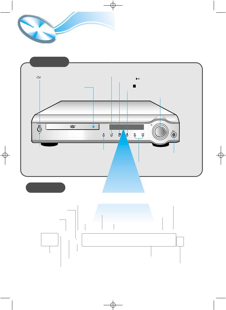
 Description
Front Panel
|
|
Function button |
|
Power ( |
) button |
Play/Pause ( |
) button |
|
|
||
|
Disc Tray |
Stop ( |
) button |
Volume control
Standby indicator |
Open/Close button |
|
Headphone Jack |
Tuning Down & Skip ( ) buttons
Tuning Up & Skip (
 ) buttons
Display
|
|
|
|
DSP |
|
|
|
|
|
|
|
|
|
|
|
|
|
|
|
||
|
|
|
|
|
|
|
|
|
||
|
|
|
|
indicator |
|
|
|
TUNER indicator |
||
|
|
|
|
|
|
|
||||
|
|
|
|
|
|
|
|
|||
|
|
|
|
|
|
PBC |
|
|
|
|
|
|
|
|
|
|
|
|
|
|
|
|
|
|
|
|
|
indicator |
|
indicator |
||
|
|
|
|
TITLE |
|
|
STEREO |
|||
|
|
|
|
|
|
|
|
|
||
LINEAR PCM |
|
PROGRAM |
|
|
|
|||||
indicator |
|
|
|
|
|
|||||
|
indicator |
|
indicator |
|
|
|
||||
|
|
|
|
|
|
|||||
|
|
|
|
|
|
|
||||
|
|
|
|
|
|
|
|
|||
|
|
|
|
LINEAR PCM DSP TITLE |
PBC PRGM |
|
ST TUNED |
|
||
|
L |
C |
R |
PRO LOGIC |
|
|
|
|
||
|
|
|
|
|
|
|
|
|||
|
|
LFE |
|
D I G I T A L |
|
|
kHZ |
|
||
|
LS |
S |
RS |
MPEG |
|
|
MHZ |
|
||
|
|
|
|
|
|
|
|
|||
SPEAKER |
MPEG indicator |
|
|
|
||||||
|
|
|
System Status Display |
|||||||
indicator |
DOLBY DIGITAL indicator |
|||||||||
|
|
|
||||||||
RADIO PRO LOGIC indicator FREQUENCY
indicator
5
DM550(GB)-noRDS 7/27/02 12:25 Page 6
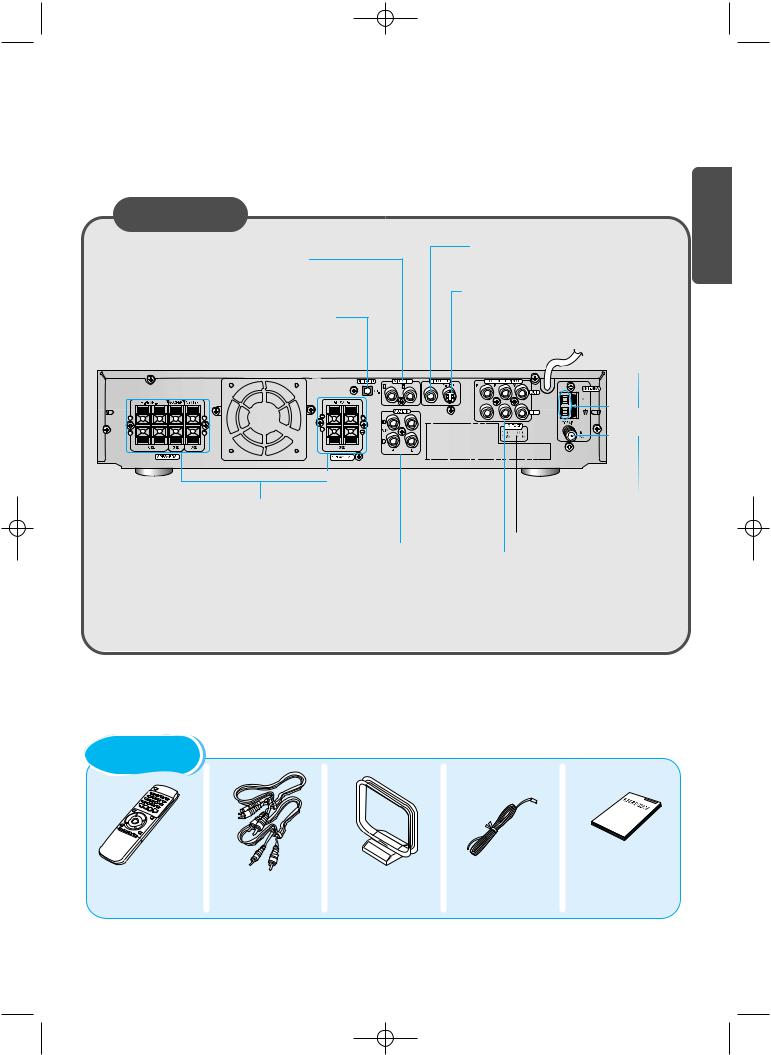
Rear Panel
External Video Component
Input Connector
External Digital Component Input Connectors
Use these for connections to external equipment capable of digital output.
Video Output Connector
Connect the TV's video input jacks (VIDEO IN) to the VIDEO OUT connector.
S-Video Output Connector
If the TV is equipped with an S-Video input connector (S-VIDEO IN), connect it to the player's S-Video output jack.
AM Antenna
Connector
PREPARATION
5.1 Channel Speaker
Output Terminals
External Audio Component
Input Connector
FM Antenna |
Connector |
Voltage Selector(option) |
COMPONENT VIDEO OUTPUT/INPUT jacks
Connect a TV with component video input jacks to these jacks.
Accessories
Remote Control |
Video/Audio Cable |
AM Antenna |
FM Antenna |
User's Manual |
6

DM550(GB)-noRDS 7/27/02 12:25 Page 7


 Remote Control Unit
DVD POWER button |
|
|
DVD button |
TV |
|
TV Power button |
||
TUNER button |
TV/VIDEO |
|
TV/VIDEO button |
||
AUX button |
Channel |
|
TV Channel Selection button |
||
|
||
Open/Close button |
Volume |
|
TV Volume Control button |
||
|
||
Title button |
Play/Pause button |
|
Menu button |
||
Stop button |
||
Audio MO/ST(mono/stereo) button |
||
Tuning Preset/CD Skip button |
||
Subtitle button |
||
|
||
Display button |
Tuning Up/Down/CD Search button |
|
|
||
Return button |
Direction/Enter button |
|
|

 Volume Control buttons
Speaker output volume control
DSP/DPL II Mode button |
Sleep button |
|
DSP/DPL II Effect button |
||
Mute button |
||
|
||
|
Sound Edit button |
|
Number(0~9) buttons |
SPK Mode button |
|
Pro Logic II button |
||
Slow button |
||
Test Tone button |
||
Angle button |
Clear button |
|
Repeat button |
||
Step button |
||
TV System/Zoom button |
||
Setup button |
||
|
||
Repeat A↔ B button |
|
|
Go To button |
Remain button |
|
|
||
D.R.C button |
Program button |
|
|
7
DM550(GB)-noRDS 7/27/02 12:25 Page 8
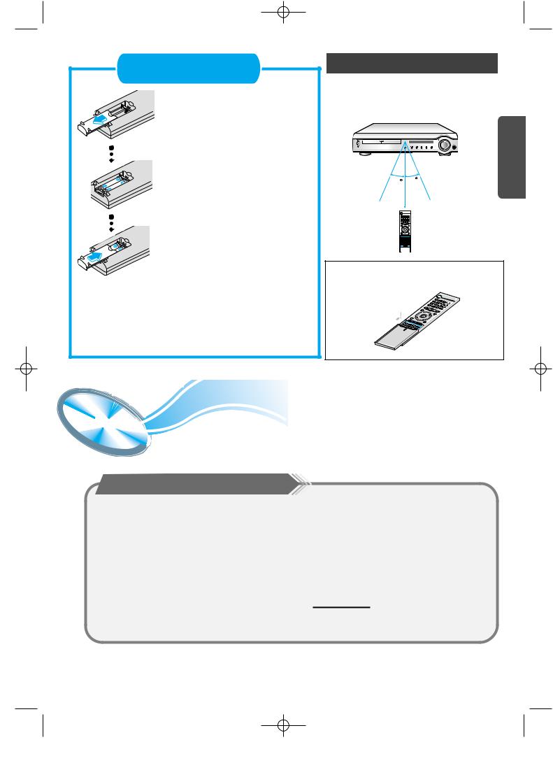
Insert Remote Batteries
1 Remove the battery cover on the back of the remote by pressing down and sliding the cover in the direction of the arrow.
2 Insert two 1.5V AAA batteries, paying attention to the correct polarities (+ and –).
3 Replace the battery cover.
Follow these precautions to avoid leaking or cracking cells:
• Place batteries in the remote control so they match the
Range of Operation of the Remote Control
The remote control can be used up to approximately 23 feet/7 meters in a straight line. It can also be operated at a horizontal angle of up to 30° from the remote control sensor.
30 |
30 |
PREPARATION |
|
||
|
7~10m |
|
To open the remote control cover, push the top of the cover, then slide downward.


 Listening on headphones
Listening on headphones
Use headphones (not supplied) for private listening pleasure.
Connect the headphones to the HEADPHONES jack of the front panel.
•No sound is produced from the speakers.
•To prevent hearing damage, do not raise the volume level excessively when using headphones.
HEADPHONE jack
8
DM550(GB)-noRDS 7/27/02 12:25 Page 9

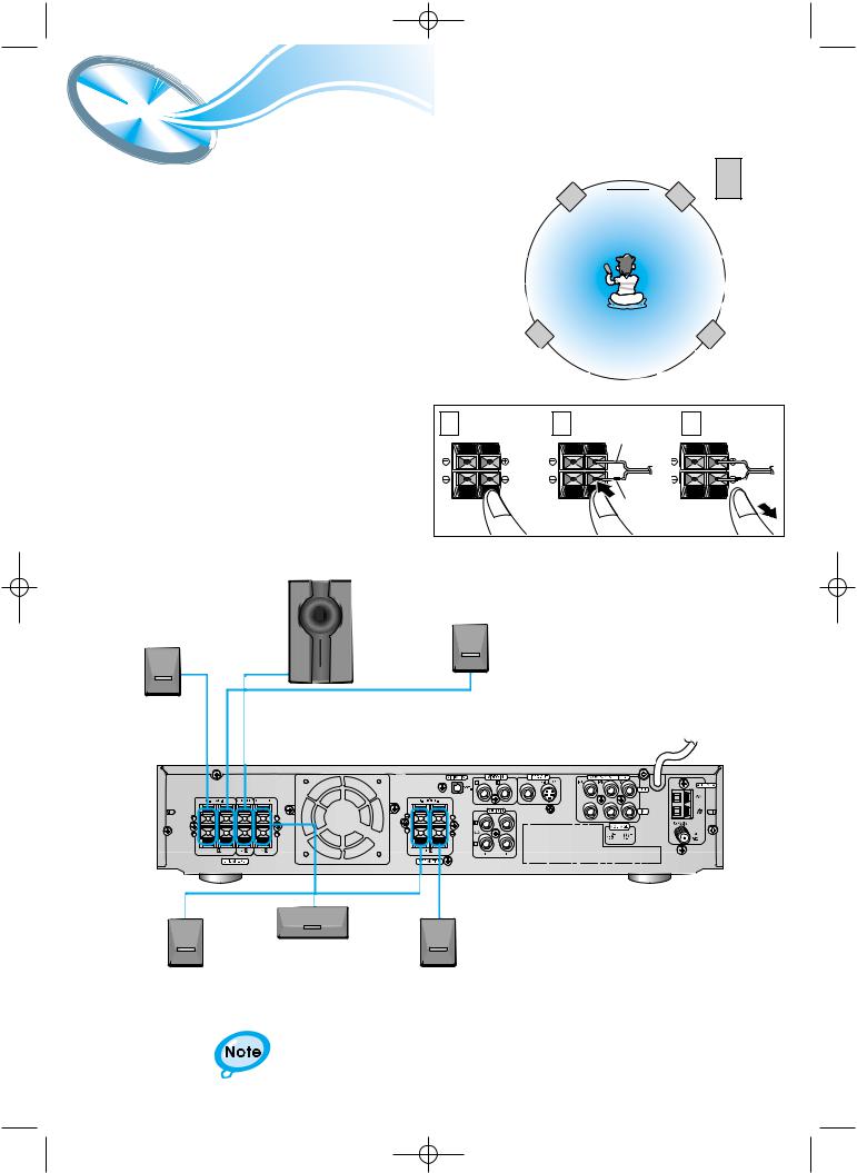
 Connecting the Speakers
Left front speaker
•Connect the satellite speakers, center speaker, and subwoofer to the terminals on the rear panel using speaker cords supplied.
•Connect the red cord to the red (+) terminal and the black cord to the black (-) terminal.
Center
speaker Right front 
 speaker
Subwoofer
Left rear |
Right rear |
speaker |
speaker |
1 Press and hold the terminal tab.
2 Insert the speaker cord.
3 Release the finger.
Subwoofer
Right rear speaker
1 |
2 |
3 |
|
|
Red |
|
|
Black |
Left rear speaker
Center speaker
Right front speaker |
Left front speaker |
• For details on the “Ideal Speaker Placement” see page 32.
9
DM550(GB)-noRDS 7/27/02 12:25 Page 10


 Connect Video to TV
CONNECTIONS
TV
Composite S-Video |
Component |
Video |
Video |
* Depending on your TV, Component Video input connectors may be marked as DVD Video input connectors.
Composite Video (Good Quality)
Connect the supplied video cable from the VIDEO OUT jack on the back panel of the system to the VIDEO IN jack on your television.
S-Video (Better Quality)
If you television is equipped with an S-Video input, connect an S-Video cable (not supplied) from the S-VIDEO OUT jack on the back panel of the system to the S-VIDEO IN jack on your television.
Component Video (Best Quality)
If your television is equipped with Component Video inputs, connect a component video cable (not supplied) from the Pr, Pb and Y jacks on the back panel of the system to the corresponding jacks on your television.
•When the Progressive scan mode is selected, the VIDEO and S-VIDEO outputs do not feed any signals.
10

DM550(GB)-noRDS 7/27/02 12:25 Page 11


 Connecting the FM and AM(MW/LW) Antennas
If AM reception is poor, connect an |
1 |
2 |
3 |
|
outdoor AM antenna(not supplied). |
||||
|
|
|
If FM reception is poor, connect an outdoor FM antenna (not supplied).
AM Loop Antenna (supplied)
Snap the tabs on the loop into the slots of the base to assemble the AM loop antenna.
FM Antenna (supplied)
Cooling fan (See “About Cooling Fan” below.)
FM antenna connection
1.Connect the FM antenna supplied to the FM 75Ω
COAXIAL terminal.
2.Slowly move the antenna wire around until you find a location where reception is good, then fasten it to a wall or other rigid surface.
•If reception is poor, connect an outdoor antenna. Before attaching a 75Ω coaxial cable (with a standard type connector), disconnect the supplied FM antenna.
AM(MW/LW) antenna connection
1.Connect the AM loop antenna supplied to the AM and  terminals.
2.If reception is poor, connect an outdoor single vinyl-covered wire to the AM terminal. (Keep the AM loop antenna connected).
(About the cooling fan)
A cooling fan is mounted on the rear panel of the center unit to prevent abnormal temperature inside the center unit, thus assuring normal operation. The cooling fan automatically starts rotating to supply external cool air to the inside of the center unit when the internal temperature exceeds the specified limit.
For safety, observe the following carefully.
•Make sure there is good ventilation around the center unit. Poor ventilation could overheat and cause damage.
•DO NOT block the cooling fan and the ventilation openings or holes. (If they are blocked by a newspaper or cloth, etc., the heat may not be able to escape.)
11

DM550(GB)-noRDS 7/27/02 12:25 Page 12


 AUX Connections
External Digital
Components
For connection to external equipment with digital output.
Example: CD recorders, MD (Mini Disc) D/A converters or other components equipped with digital output jacks
(not supplied) |
Optical Cable |
TV
To view pictures from external input, first
connect the VIDEO IN VIDEO IN jack and then connect the
VIDEO OUT jack.
CONNECTIONS
Audio Cable (Red/White)
If the external analog
component has only one Video Cable output jack, you may connect
either L or R.
External Analog
Components
R |
L |
VIDEO OUT |
Connect to external equipment with analog output.
Example: Video, TV, etc.
To Play External Digital/Analog Equipment
Press AUX on the remote control to select DIGITAL IN, AUX1, or AUX2. Press Function on the main unit to select DIGITAL IN, AUX1, or AUX2.
•Each time the button is pressed the mode switches as follows: FM AM DVD DIGITAL IN AUX 1 AUX 2.
•Always connect the video and audio connection cables to the equivalent colored jack.
12

DM550(GB)-noRDS 7/27/02 12:25 Page 13

 Controlling a TV with the Remote
You can use the remote control to operate other manufactures’ TV.
1 |
Turn on the TV. |
|
2 |
Point the DVD’s remote at the TV. |
|
3 |
TV |
|
While holding the |
button down, enter the |
|
code for your brand. |
|
|
•If there is more than one code listed in the table, enter one at a time to determine which code works.
|
example : For SAMSUNG 1TVs |
TV |
|||||||
|
|
While holding down the |
button, |
||||||
|
|
enter |
|
|
|
|
. |
|
|
|
|
|
|
|
|
|
|
|
|
4 |
If the TV turns off, setup is complete. |
||||||||
• Now, you can perform the following operations on the TV. |
|||||||||
|
|
|
|
|
|
||||
|
|
TV |
: Turn on or off the TV. |
|
|
||||
|
|
VOLUME +/– |
: Adjust the volume. |
|
|
||||
|
|
|
|
|
|||||
|
|
TV/VIDEO |
: Set the input mode (either TV or VIDEO) |
|
|||||
|
|
CHANNEL +/– |
: Change the channels. |
|
|
||||
|
|
|
|
|
|
|
|
|
|
|
|
|
|
|
|
|
|
|
|
Manufacturer |
CODES |
Samsung |
01~06,32 |
Akai |
12 |
FIisher |
12 |
Grundig |
09,17,21 |
Hitachi |
11,13,14,24 |
JVC |
32 |
LG |
02,30 |
Mitsubishi |
02,16 |
Mival |
29 |
Nokia |
23 |
Nordmende |
13,14,24 |
Panasonic |
08,23~27 |
Philips |
02,20,22 |
Saba |
13,14,22~24 |
Sanyo |
12,16 |
Schneider |
02 |
Sharp |
10,31 |
Sony |
15,16 |
Telefunken |
14,24,28 |
Thomson |
13,14,24,33,34 |
Toshiba |
07,16~19,21 |
• Manufacturers’ codes are subject to change without notice. If they are changed, this remote control cannot operate the equipment.


 Connecting your System to the Power Supply
The main lead must be plugged into an appropriate socket.
Before plugging your system into a main socket, you must check the voltage.
Check the position of the voltage selector on the rear of the system (OPTIONAL).
1.Plug the main lead (marked AC Cord on the rear of the system) into an appropriate socket.
2.Press the On/Standby button to switch your DVD Player system on.
13

DM550(GB)-noRDS 7/27/02 12:25 Page 14

 Before Using the DVD Player
Your DVD player is capable of playing DVD, VCD, and CD discs.
User instructions may vary depending on the type of disc. Read the instructions carefully before use.
|
1 |
2 |
3 |
|
Turn on the power |
Select a video mode by |
Press the DVD button |
Prepe- |
to your DVD player |
pressing the TV/VIDEO |
to select the DVD input |
rations |
and TV. |
button. |
function. |
before |
TV |
TV/VIDEO |
DVD |
use |
|
||
|
|
|
• The “WAIT” message that appears on the display for about 4~5 seconds when turning on the power or selecting a DVD function indicates a stabilization period for optimizing the condition of your DVD player. While the message is being displayed, other buttons remain inactive.
•When the power is not turned on, press down the Stop (  ) button on the main unit for over 5 seconds.
The product will be initialized to its optimum state.
•As to some operational features such as the Speaker mode, Test tone, Volume, etc. your DVD player will not display their operation on the TV screen.
TV Broadcast System
•This device is designed to work with the PAL video format.
•For normal playback, the video format a DVD disc is recorded in must coincide with your TV's video format.
TV System Selection
Press the TV System button while in stop mode.
•Each time the TV System button is pressed, “NTSC, PAL” are selected in this order.
•Different countries use different types of TV broadcast systems, video,
audio and channel systems.
Example : The player cannot playback PAL-encoded DVD with NTSC-TV.
CONNECTIONS
14
 Loading...