How it Works
Log In / Sign Up
0
My Files
0
My Downloads
185710
History
Account Settings
Log Out
Buy Points
How it Works
FAQ
Contact Us
Questions and Suggestions
Users
show menu
Samsung
Loading...
A
AQ07TSBN
AQ07XAN
AQ07XLN
AQ09
3
AQ09ASANSER
AQ09C8ME
AQ09FA
AQ09FAN
AQ09FD
AQ09MA
AQ09MSBN
AQ09NSA
AQ09NSBX
AQ09NSDX
AQ09TSBN
AQ09UGDX
AQ09VBAN
AQ09XAN
AQ09XLN
AQ12A5MB
AQ12BA
AQ12ESBT
AQ12FA
AQ12FAN
AQ12FCX
AQ12FKX
AQ12MSDX
AQ12NSBN
AQ12U
AQ12UGEN
AQ12UGF
AQ12VWAX
AQ18
4
AQ18A9
AQ18BAX
AQ18FA
AQ18FAN
2
AQ18JWAX
AQ18UBBX
AQ18UGEN
AQ18UUAX
AQ18VBAX
AQ18WJWE
AQ24UGAN
2
AQB24J2WC
AQT18A0RE
AQT24
AQT24P6GEE
AQV-09-KBAN
AQV09AWAX
AQV09FAN
AQV09FAX
AQV09FC
2
AQV09FKN
AQV09MWAX
AQV09NSAN
AQV09PSBX
AQV09PSDN
AQV09PSDX
AQV09UGAN
AQV09VBAN
AQV09VBEN
AQV09VC
AQV12
AQV12AWBN
AQV12EWAN
AQV12F2VE
AQV12FA
3
AQV12NSBN
AQV12PSBN
AQV12PWAX
AQV12UGAN
AQV12VBA
AQV12VSDX
AQV18MSAX
AQV18NSAX
AQV18NSD
AQV18UGAN
AQV18UWBX
AQV18VC
AQV24FCN
AQV24J
AQV24MSAN
AQV24MWAN
AQV24NSFX
AR09FSSSBWKN
AR09HQFSAWK
AR09HSFNCWKN
AR09HSFNRWKN
AR09JQFSAWKNER
AR12FSFPKGMN
AR12HQFNAWKN
AR12HSFSBURN
AR12HSSDRWK
AR12KSWSBWKN
AR18
AR24HSFNCWKN
AR24KSFHBWKN
ARN-CD61PCAQ
ARN-CP81B
Loading...
Loading...
Nothing found
AQV09FAN
User Manual
28 pgs
10.18 Mb
0
Manual
26 pgs
10.08 Mb
0
Manual [es]
26 pgs
10.1 Mb
0
Manual [pt]
26 pgs
10.05 Mb
0
Manual [de]
26 pgs
10.07 Mb
0
Programming guide
4 pgs
310.19 Kb
0
Service Manual
98 pgs
19.76 Mb
3
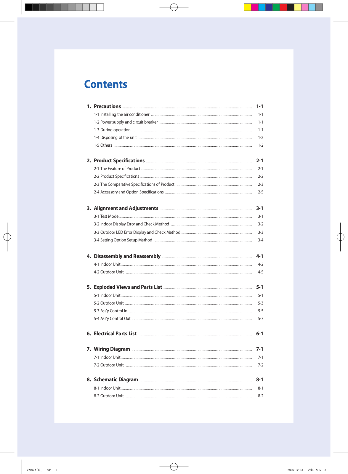
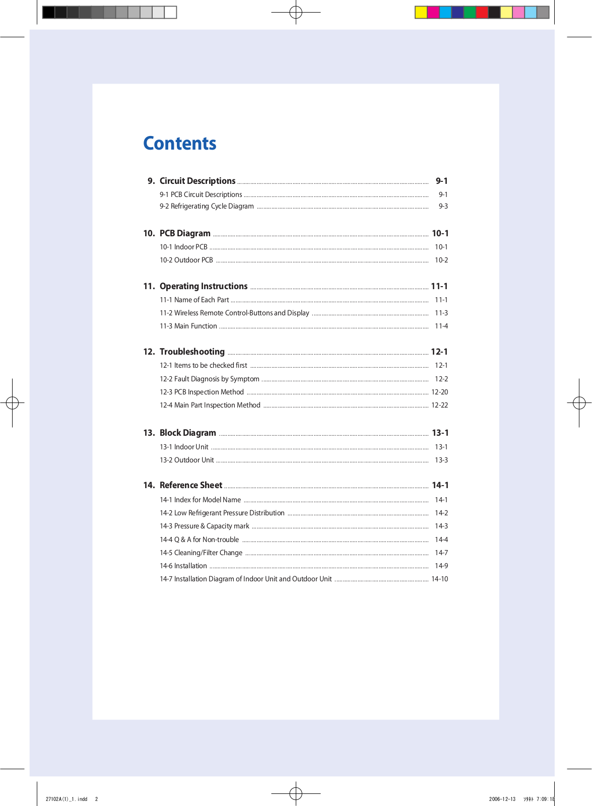
Table of contents
Loading...
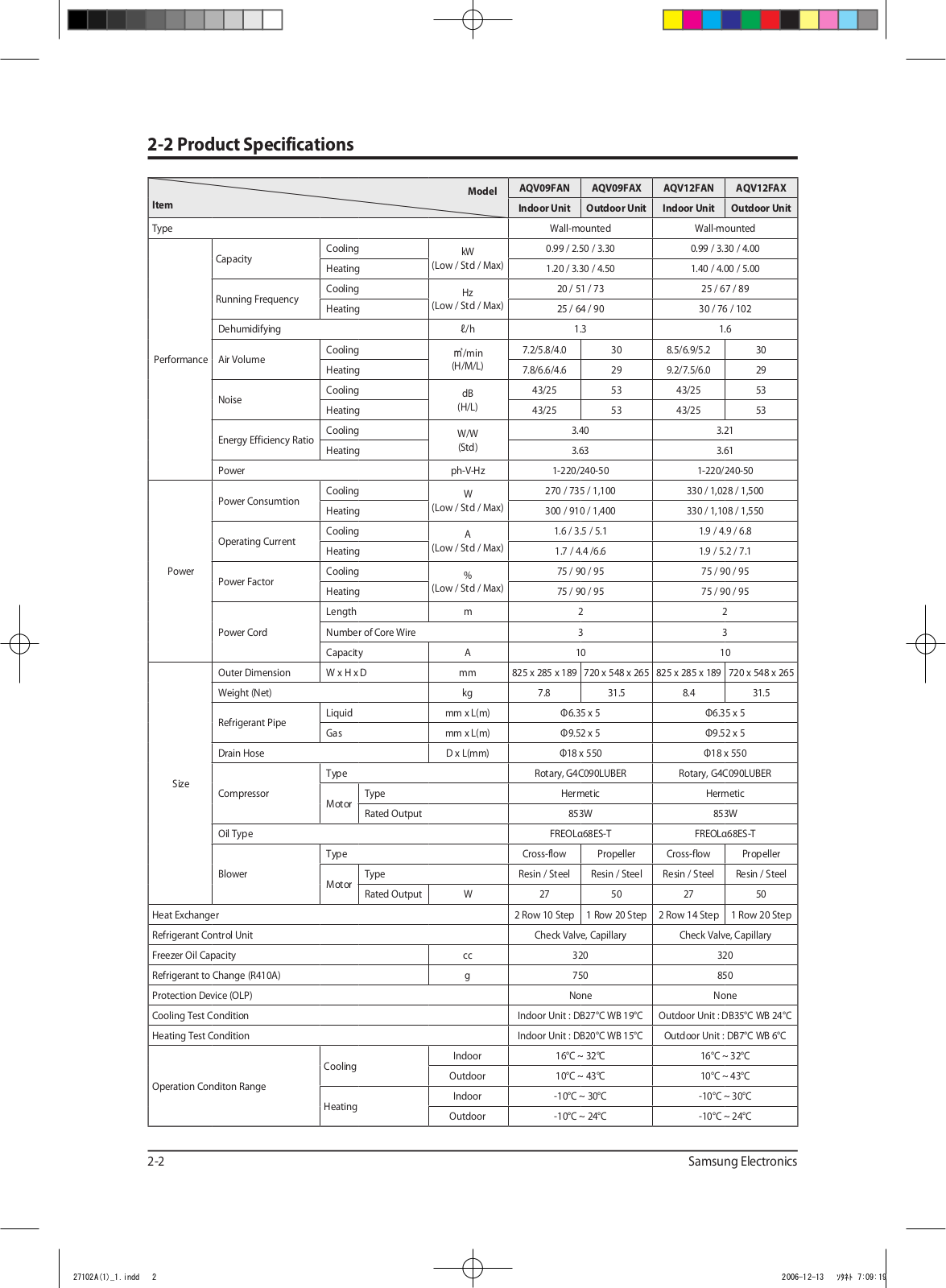
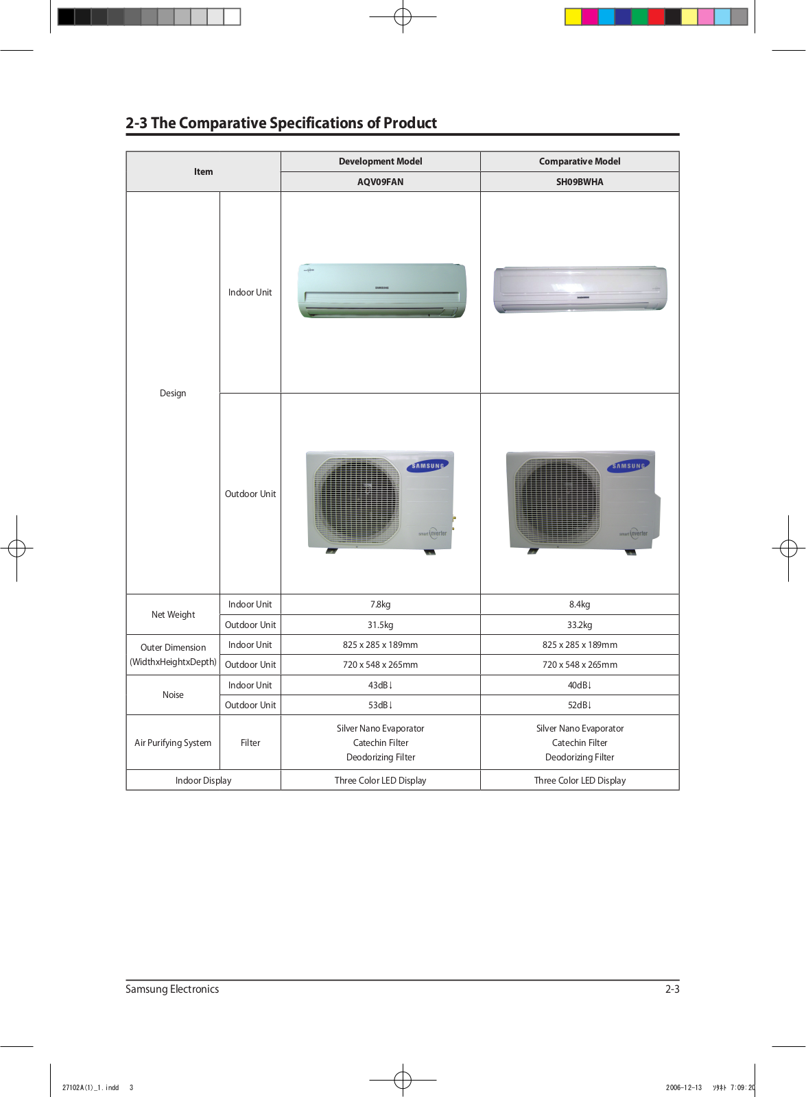
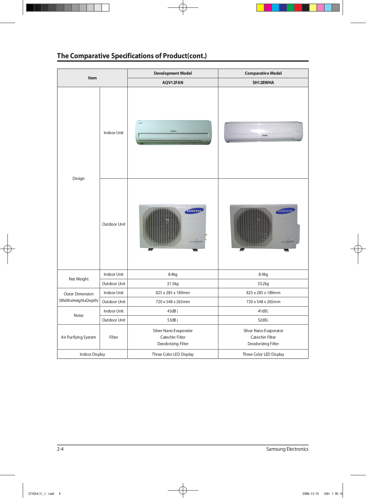
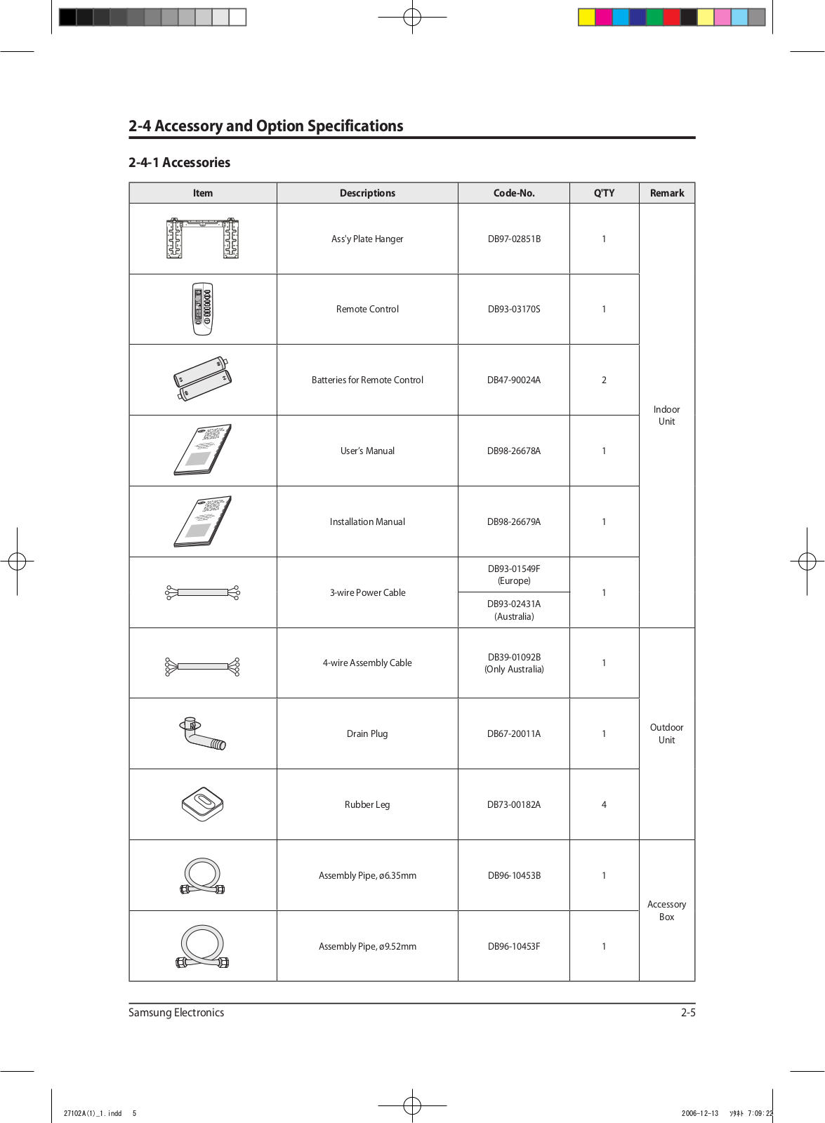
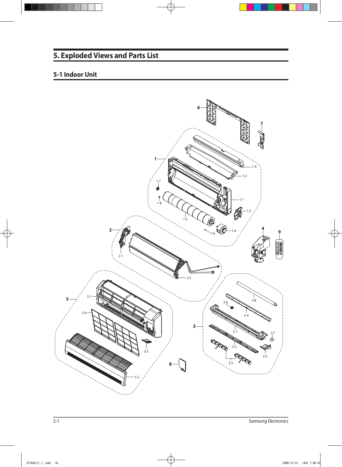
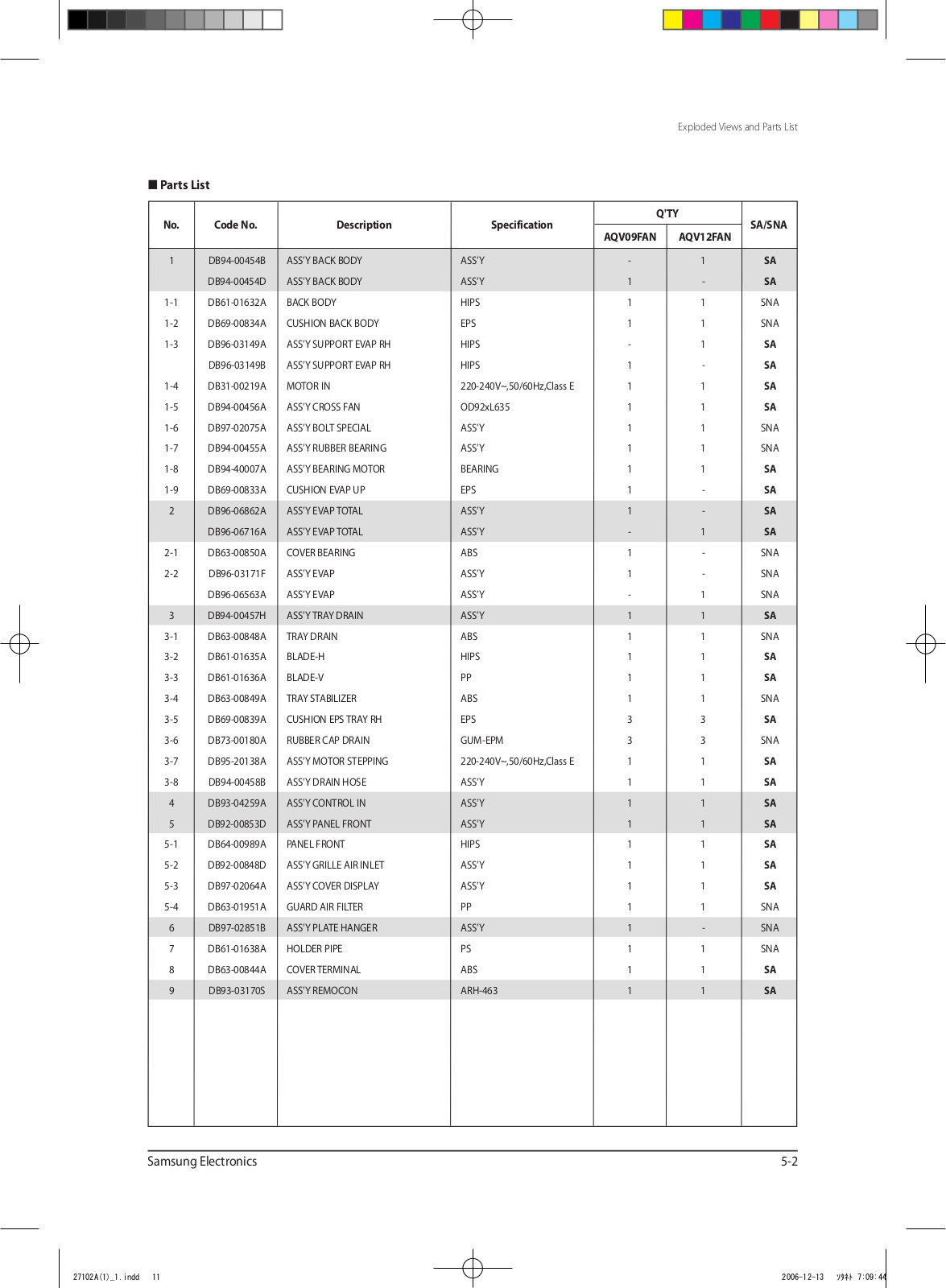
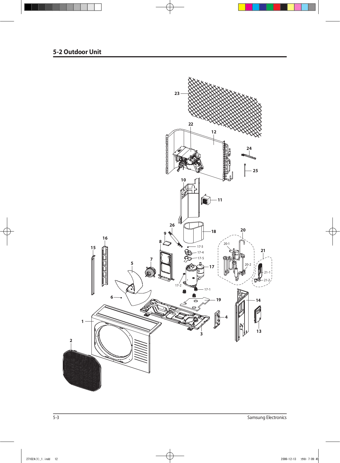
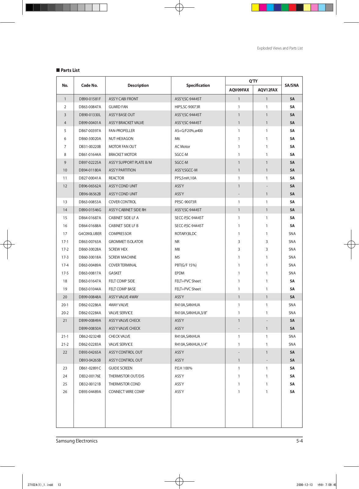
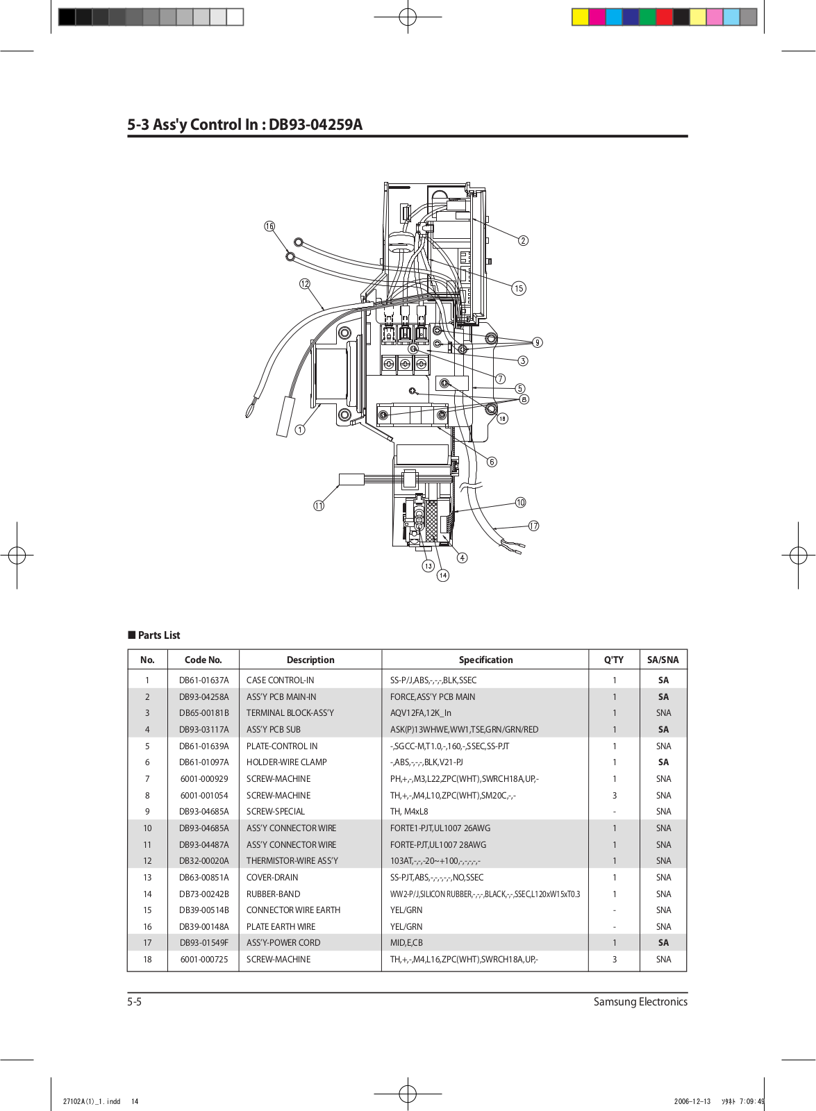
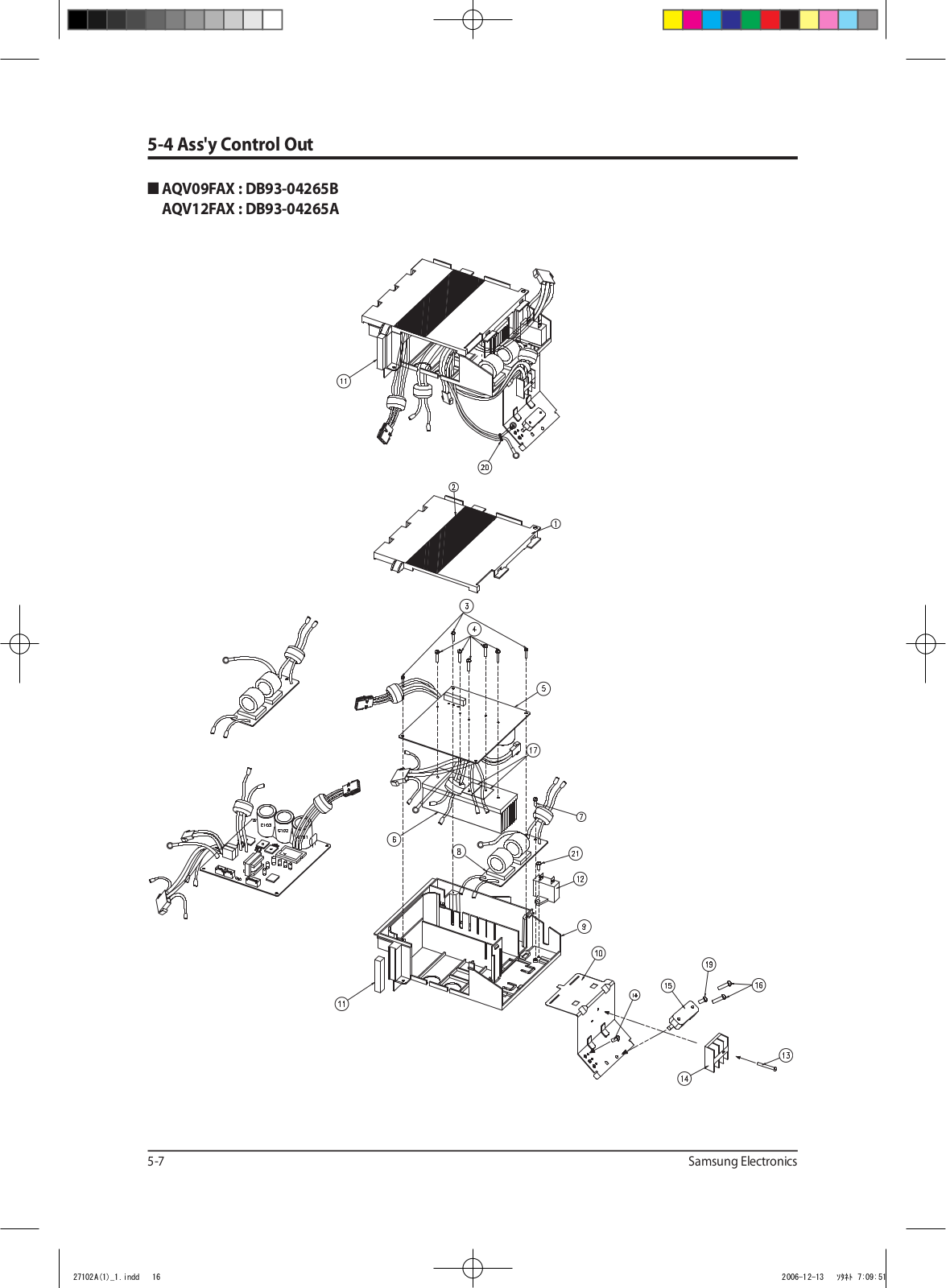
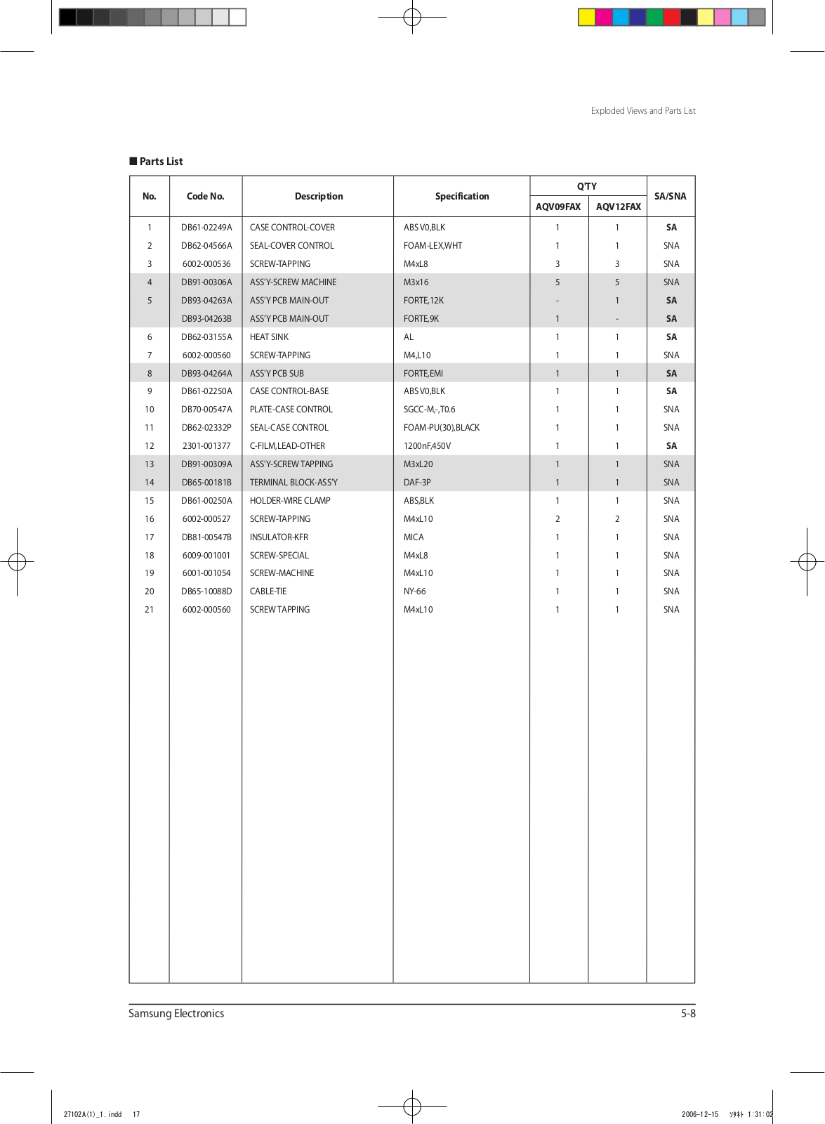
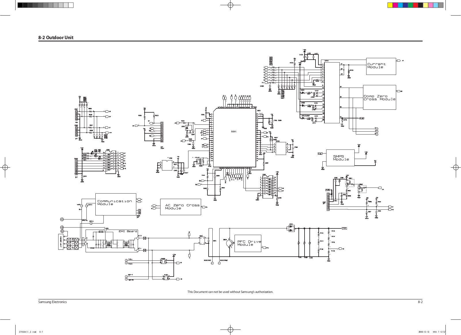
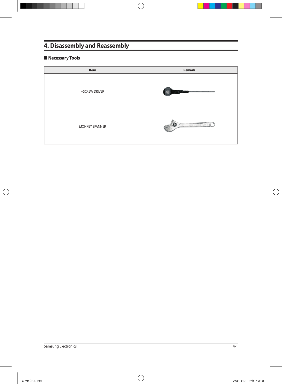
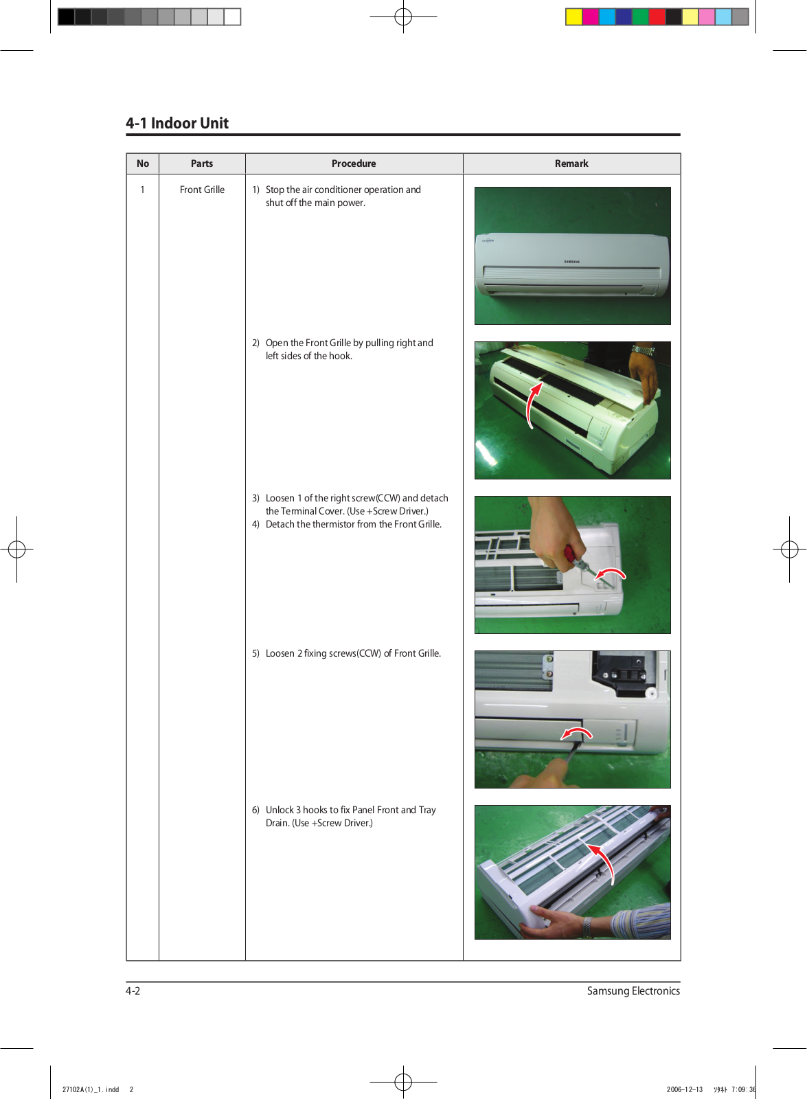
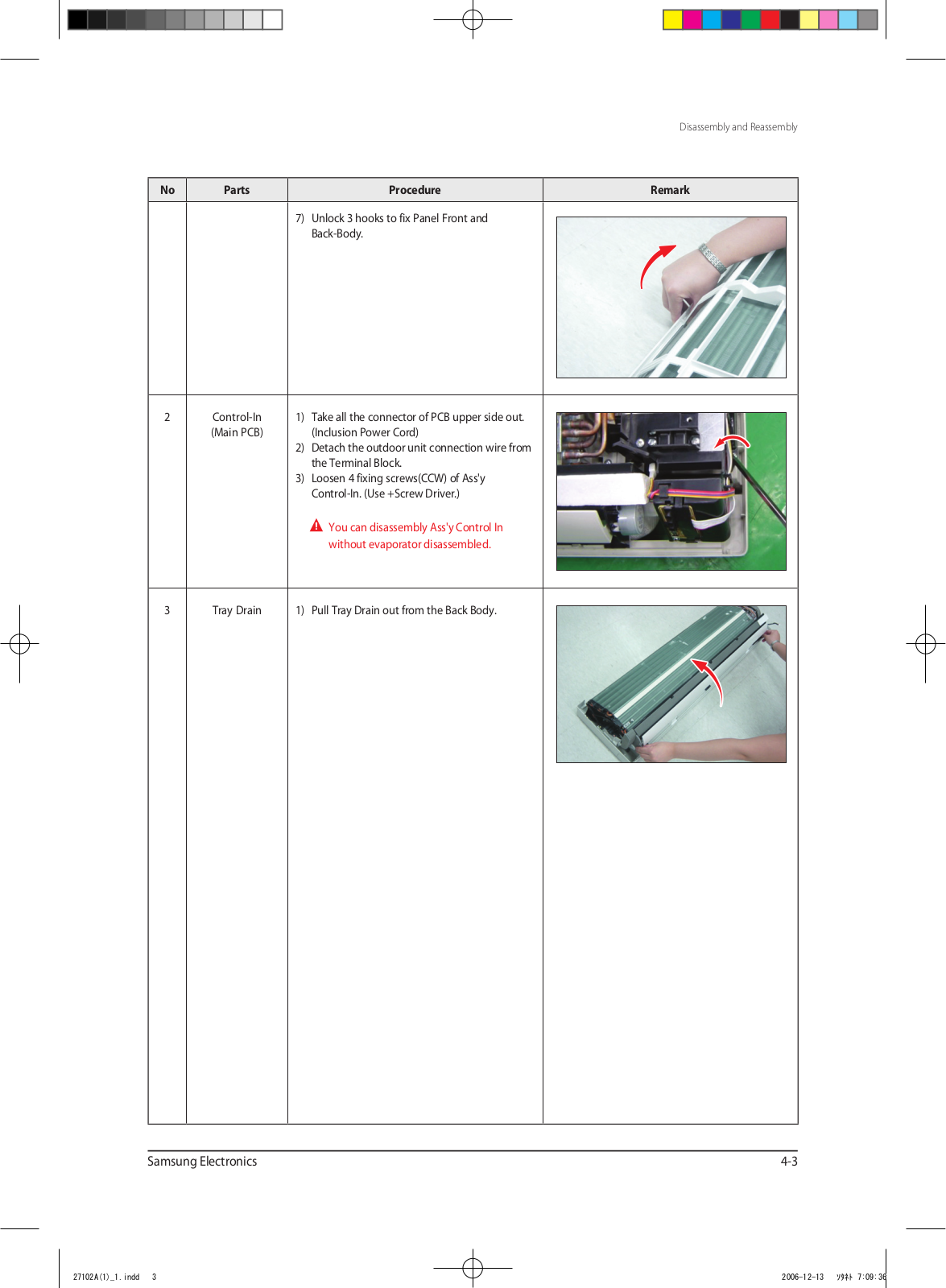
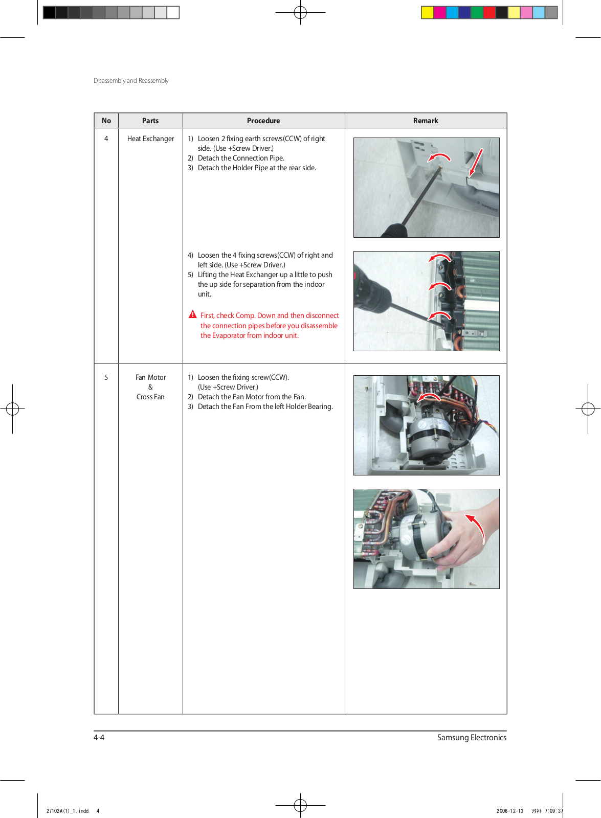
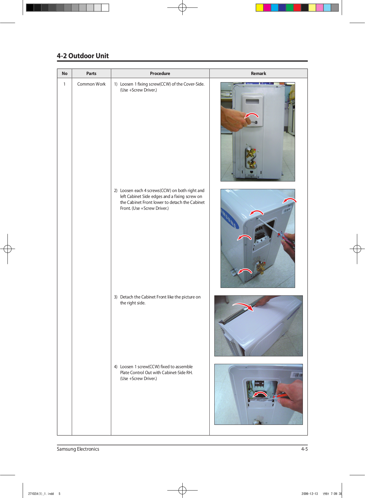
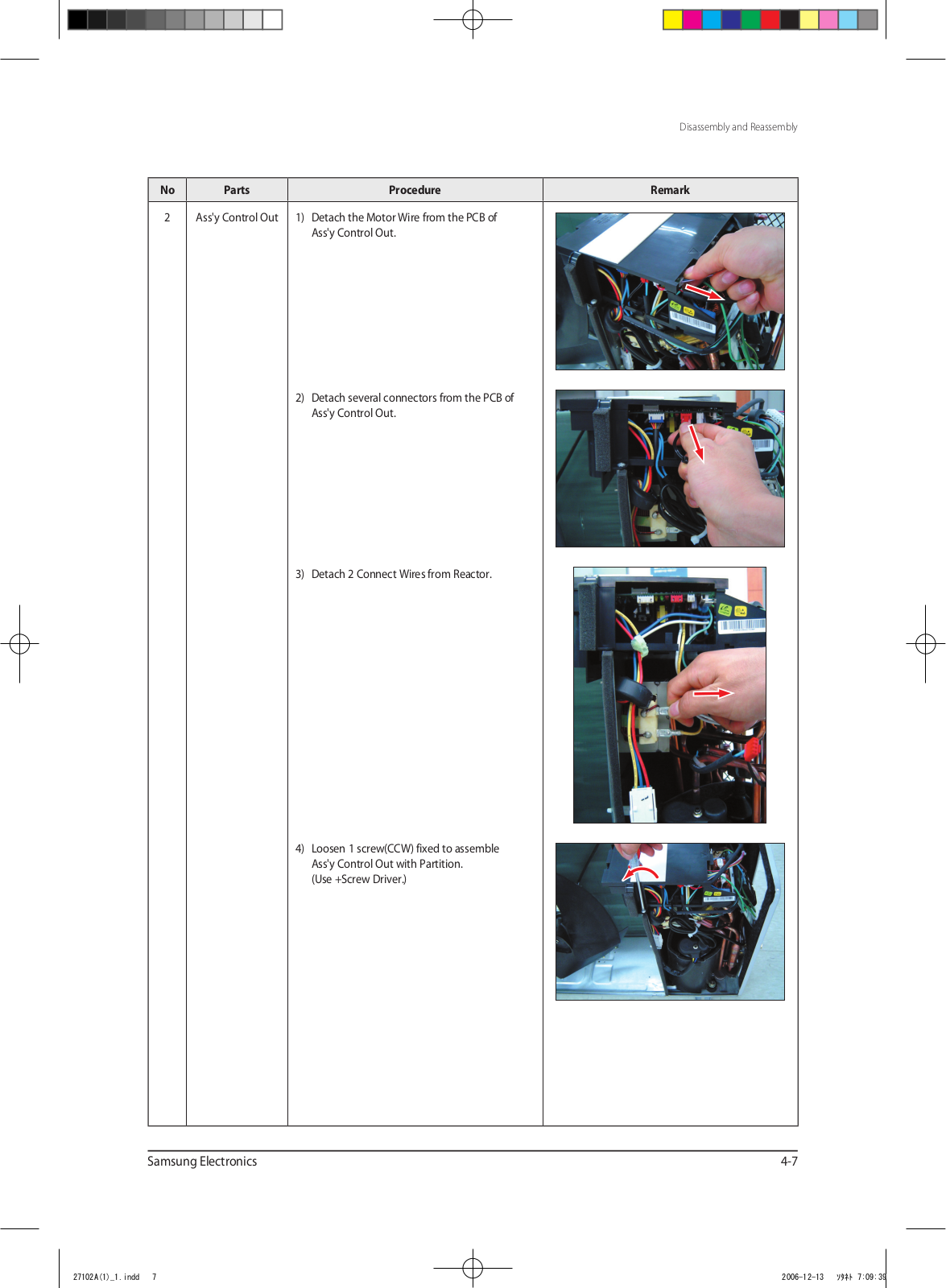
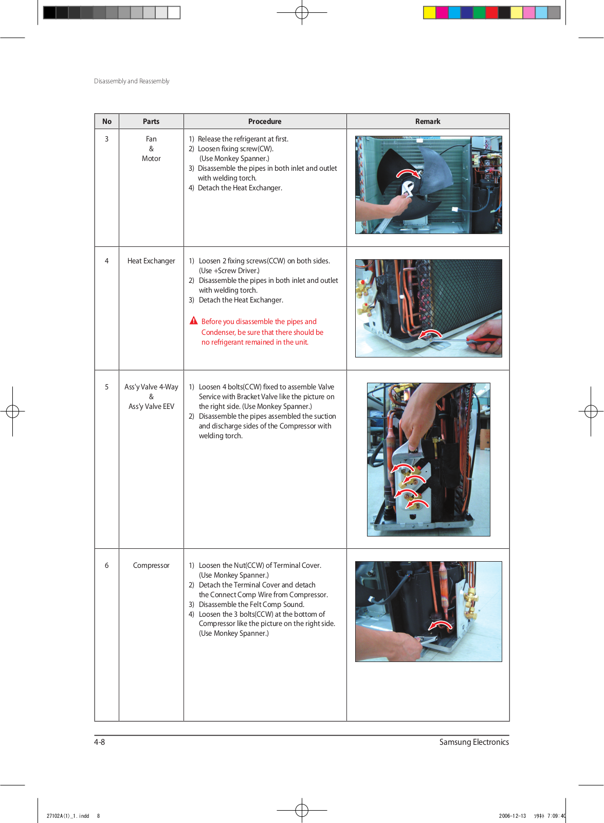
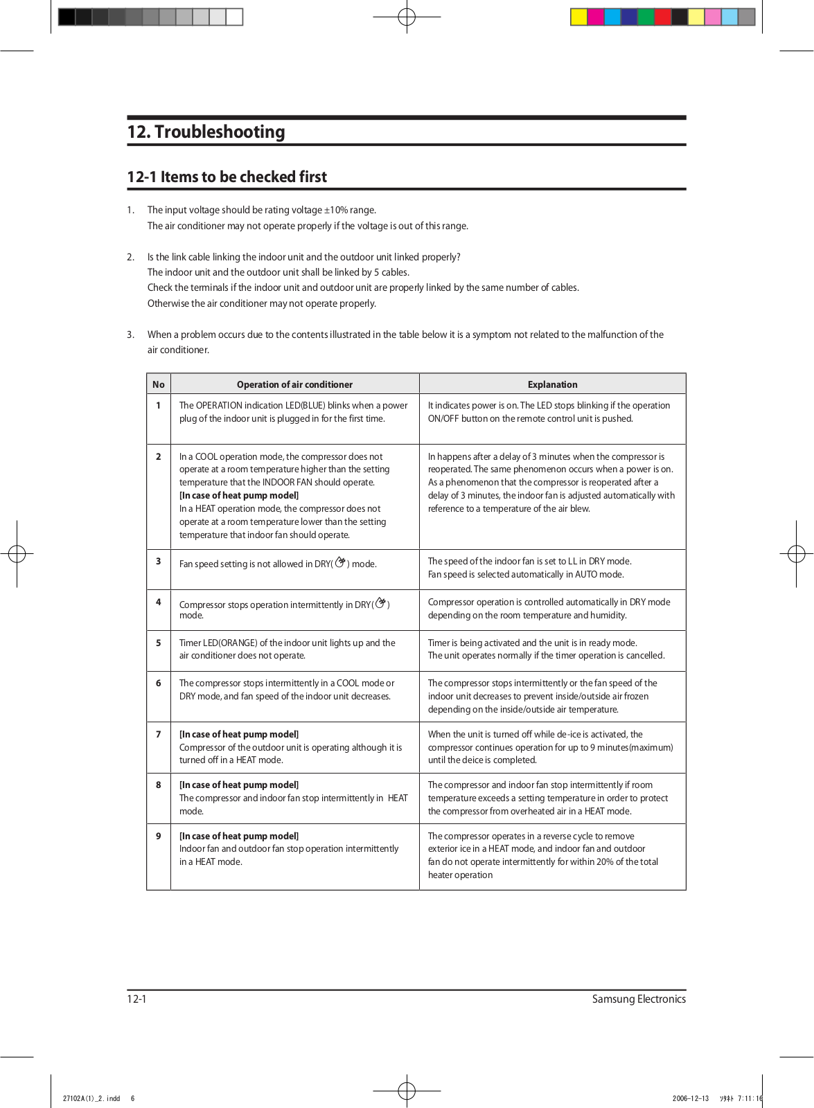
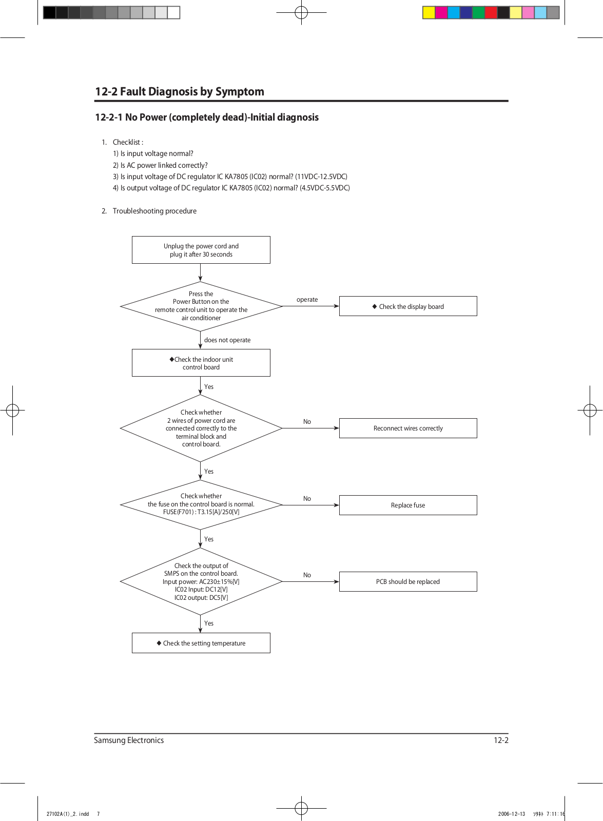
Samsung AQV09FAN, AQV09FAX, AQV12FAN, AQV12FAX Service Manual
...
Samsung Service Manual
Download
4.5
(
4
)
Loading...
+
68
hidden pages
Unhide
You need points to download manuals.
1 point = 1 manual.
You can buy points or you can get point for every manual you upload.
Buy points
Upload your manuals


 Loading... Loading...