


Samsung AQV18UGAN, AQV24UGAN, AQV18EWAN, AQV24EWAN, AQV24EWAX Service Manual
...AIR CONDITIONER
S.INVERTER
AQV18EWAN
AQV24EWAN
AQV18EWAX
AQV24EWAX
SPLIT-TYPEAIR CONDITIONER
INDOOR UNIT |
OUTDOOR UNIT |
Basic : AQV18UGAN |
|
AQV24UGAN |
|
Model: AQV18EWAN |
|
AQV24EWAN |
|
Model Code : AQV18EWAN |
AQV18EWAX |
AQV24EWAN |
AQV24EWAX |
THE FEATURE OF PRODUCT
Air Conditioner


 Mode
Mode


 Mode can help you sleep quickly and soundly and wake up refreshed.
 Silence Mode
When you use the "Silence Mode", you c n experience extremely quiet operation of your air conditioner.
Refer to the service manual in the GSPN(see the rear cover) for the more information.

Operating Instructions and Installation
Contents
11. Precautions ........................................................................................................................................ |
1-1 |
1-1 Precautions for the Service ............................................................................................................. |
1-1 |
1-2 Precautions for the Static Electricity and PL ................................................................................ |
1-1 |
1-3 Precautions for the Safety ............................................................................................................... |
1-2 |
12. Product Specifications ............................................................................................................... |
2-1 |
2-1 The Feature of Product .................................................................................................................... |
2-1 |
2-1-1 The Feature of Product ........................................................................................................... |
2-1 |
2-1-2 Modified items compared with Basic model ..................................................................... |
2-2 |
2-1-3 New components to be applied .......................................................................................... |
2-2 |
2-2 The Comparative Specifications of Product ................................................................................ |
2-3 |
2-3 Accessory and Option Specifications ........................................................................................... |
2-4 |
2-3-1 Accessories ............................................................................................................................... |
2-4 |
13. Disassembly and Reassembly .............................................................................................. |
|
|
3-1 |
3-1 Indoor Unit ......................................................................................................................................... |
|
|
3-2 |
3-2 Outdoor Unit ..................................................................................................................................... |
|
|
3-10 |
14. Troubleshooting ............................................................................................................................ |
|
|
4-1 |
4-1 Setting Option Setup Method ....................................................................................................... |
|
|
4-1 |
4-2 Display Error and Check Method .................................................................................................. |
|
|
4-4 |
4-2-1 Display Error mode ................................................................................................................. |
|
|
4-4 |
4-3 Fault Diagnosis by Symptom ........................................................................................................ |
|
|
4-6 |
4-3-1 Communication error When E101 or E102 is displayed ...................................... |
|
4-6 |
|
4-3-2 Indoor Temperature Sensor ErrorWhen |
is diplayed ....................................... |
|
4-7 |
4-3-3 Indoor Heat Exchanger Temperature Sensor ErrorWhen |
is diplayed ......... |
4-8 |
|
4-3-4 Indoor Fan Motor Speed Detecting ErrorWhen |
is diplayed ......................... |
4-9 |
|
4-3-5 MPI ErrorWhen E186 is displayed ................................................................................... |
|
|
4-10 |
4-3-6 Outdoor temperature sensor error When E221 is displayed............................................ |
|
4-11 |
|
4-3-7 Coll temperature sensor error When E237 is displayed...................................................... |
|
4-12 |
|
4-3-8 Discharge temperature sensor error When E251 is displayed.......................................... |
|
4-13 |
|
4-3-9 Discharer over termperature sensor errorWhen E416 is displayed................................ |
4-14 |
||
4-3-10 The outdoor unit fan error When E458 is displayed............................................................. |
|
4-15 |
|
4-3-11 Compressor start errorWhen E461 is displayed..................................................................... |
|
4-16 |
|
4-3-12 I_Trip error When E462 is displayed........................................................................................... |
|
|
4-17 |
4-3-13 O.C.(over current)error When E464 is displayed..................................................................... |
|
4-18 |
|
4-3-14 Comp Rotation error When E467 is displayed........................................................................ |
|
|
4-19 |
4-3-15 Current sensor errorWhen E468 is displayed......................................................................... |
|
|
4-20 |
4-3-16 DC-Link voltage sensor errorWhen E469 is displayed........................................................ |
|
4-21 |
|
4-3-17 OTP error When E471 is displayed............................................................................................... |
|
|
4-22 |
Samsung Electronics |
1 |

Operating Instructions and Installation
Contents
4-3-18 AC Line Zero Cross signal out error When E472 is displayed .................................... |
4-22 |
4-3-19 Operation condition secession errorWhen E400/441 is displayed.............................. |
4-23 |
4-3-20 Capacity miss match error When E556 is displayed........................................................... |
4-23 |
4-3-21 DC-Link voltage under/over error When E466 is displayed............................................. |
4-24 |
4-3-22 No Power (completely dead)-Initial diagnosis (Not displayed) ..................................... |
4-25 |
4-3-23 The outdoor unit power supply error (Not displayed)............................................................ |
4-26 |
4-3-24 When the Up/Down Louver Motor Does Not Operate. (Initial Diagnosis) (Not displayed) .... |
4-27 |
4-3-25 When the remote control is not receiving ........................................................................ |
4-28 |
4-4 PCB Inspection Method .................................................................................................................. |
4-29 |
4-4-1 Pre-inspection Notices............................................................................................................................. |
4-29 |
4-4-2 Inspection Procedure............................................................................................................................... |
4-29 |
4-4-3 Indoor Detailed Inspection Procedure ............................................................................................. |
4-29 |
4-4-4 Outdoor Detailed Inspection Procedure.......................................................................................... |
4-30 |
4-5 Main Part Inspection Method ........................................................................................................ |
4-31 |
15. Exploded Views and Parts List ............................................................................................. |
5-1 |
5-1 Indoor Unit ......................................................................................................................................... |
5-1 |
5-2 Outdoor Unit ..................................................................................................................................... |
5-3 |
5-3 Ass'y control in ................................................................................................................................................. |
5-5 |
5-4 Ass'y control out ................................................................................................................................................. |
5-7 |
16. Elecrtical Parts List ................................................................................................... |
6-1 |
17. Wiring Diagram .............................................................................................................................. |
7-1 |
7-1 Indoor Unit ......................................................................................................................................... |
7-1 |
7-2 Outdoor Unit ..................................................................................................................................... |
7-2 |


 10-4
10-4
11
11-1 |
|
|
||
11-2 |
|
11-2 |
||
12 |
|
|
|
|
|
|
|
12-1 |
|
|
|
|
|
|
|
|
|
|
12-1 |
12-1 |
|
|||
|
|
12-2 |
|
12-2 |
|
|
12-3 |
|
12-3 |
|
|
12-4 |
|
12-4 |
|
|
12-5 |
|
12-7 |
|
|
12-6 |
|
12-9 |
|
|
12-7 |
|
12-10 |
|
|
|
|
|
2 |
Samsung Electronics |
11 |
11-1 |
HUMDITY CONTROL |
MPI DRIVE |
11-1 |
11-2
11-2
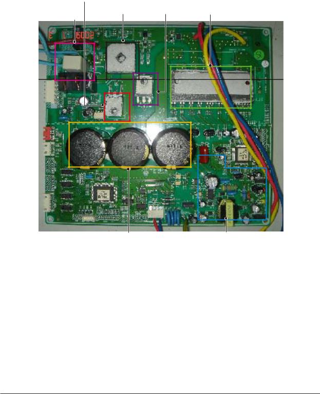
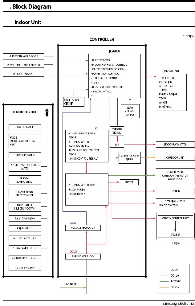
Block Diagram
IGBT
B/D |
DIODE |
IPM |
OUTDOOR FAN
DC_LINK CAP |
SMPS |
|
Samsung Electronics |
11-3 |

$JSDVJU %FTDSJQUJPOT
1$# $JSDVJU %FTDSJQUJPOT
*OEPPS 6OJU
|
4.14 1"35 |
|
#6;;&31"35 |
|
*/%003 '"/ $0/530- |
|
46#1$#$0//&$503 |
|
;&30$3044*/( 1"35 |
|
%*41-": 1"35 |
|
*/%0035&.1&3"563& 4&/403 |
|
45&1.0503 *0/ |
|
.1* 1"35 |
|
)6.*% 1"35 |
5IJT %PDVNFOU DBO OPU CF VTFE XJUIPVU 4BNTVOHT BVUIPSJ[BUJPO
4BNTVOH &MFDUSPOJDT |
|
Circuit Descriptions |
Circuit Descriptions |
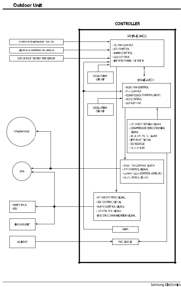
9-1-2 Outdoor Unit
Samsung Electronics |
9-2 |
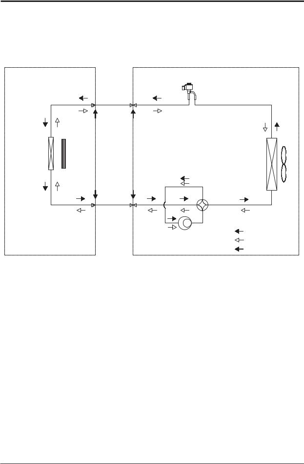
3FGSJHFSBUJOH $ZDMF %JBHSBN
*OEPPS 6OJU |
0VUEPPS 6OJU |
)FBU
&YDIBOHFS &WBQPSBUPS
$SPTT'BO
XBZWBMWF
&YQBOTJPOWBMWF
-JRVJE TJEF
)FBU |
1SPQFMMFS'BO |
|
|
&YDIBOHFS |
|
$POEFOTFS |
|
(BT TJEF
XBZWBMWF |
|
XBZWBMWF |
|
$PNQSFTTPS |
$PPMJOH |
|
|
|
|
|
)FBUJOH |
|
|
(BT-FBL$IFDL1PJOU |
|
4BNTVOH&MFDUSPOJDT |
3. Disassembly and Reassembly
Necessary Tools
Item |
Remark |
+SCREW DRIVER
MONKEY SPANNER
Samsung Electronics |
3-1 |
3-1 Indoor Unit
No |
Parts |
Procedure |
Remark |
|
|
|
|
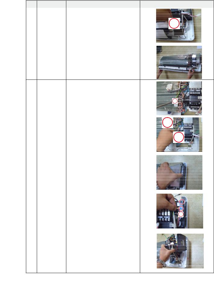
1 |
PANEL-FRONT |
1) Stop the driving of air conditioner and shut off |
|
|
|
main power supply. |
|
|
|
2) Open the FRONT-GRILLE and pull out from the |
|
|
|
PANEL-FRONT. |
|
3)Detach COVER-TERMINAL from the PANELFRONT.(use + Screw Driver)
4)Loosen connector wire(white) and detach the temperature sensor wire.
5)To detach the FRONT-PANEL the main frame, unfasten 2 screw at the bottom.(use + Screw Driver)
6) Take off the FRONT-PANEL,lifting up the bottom.
3-2 |
Samsung Electronics |
Operating Instructions and Installation
No |
Parts |
Procedure |
Remark |
|
|
|
|
2 |
TRAY DRAIN |
1) Loosen stepping motor wire and detach the |
|
|
|
hook of main frame. |
|
2)To detach TRAY-DRAIN from the main frame, pull the bottom of the TRAY-DRAIN towards you.
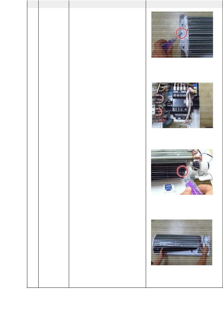
3 |
CONTROL IN |
1) Unfasten the earth screw.(use + Screw Driver) |
2)Detach the temperature sensor and Humidity sensor.
3)Detach COVER-CONTROL from the CASECONTROL.
4)Loosen MPI connector wire(yellow), and MOTOR
wires(white,blue).
5)Take off the CASE-CONTROL from the main frame.
Samsung Electronics |
3-3 |
Operating Instructions and Installation
No |
Parts |
Procedure |
Remark |
|
|
|
|
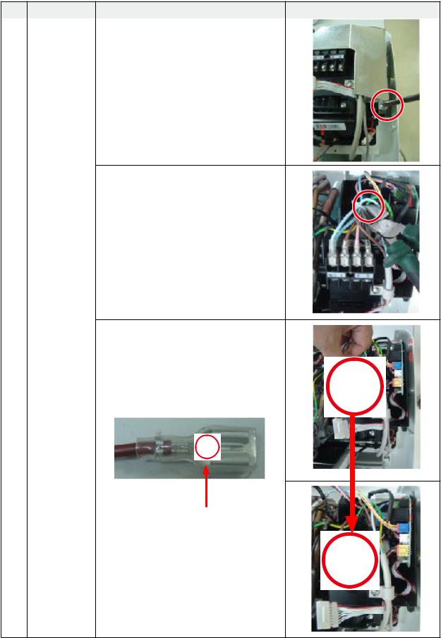
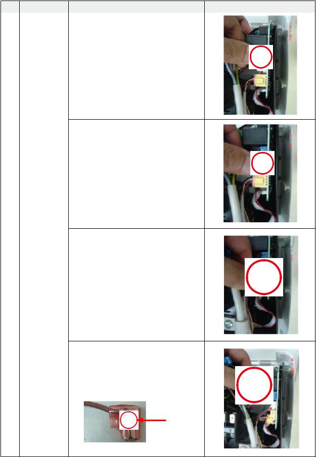
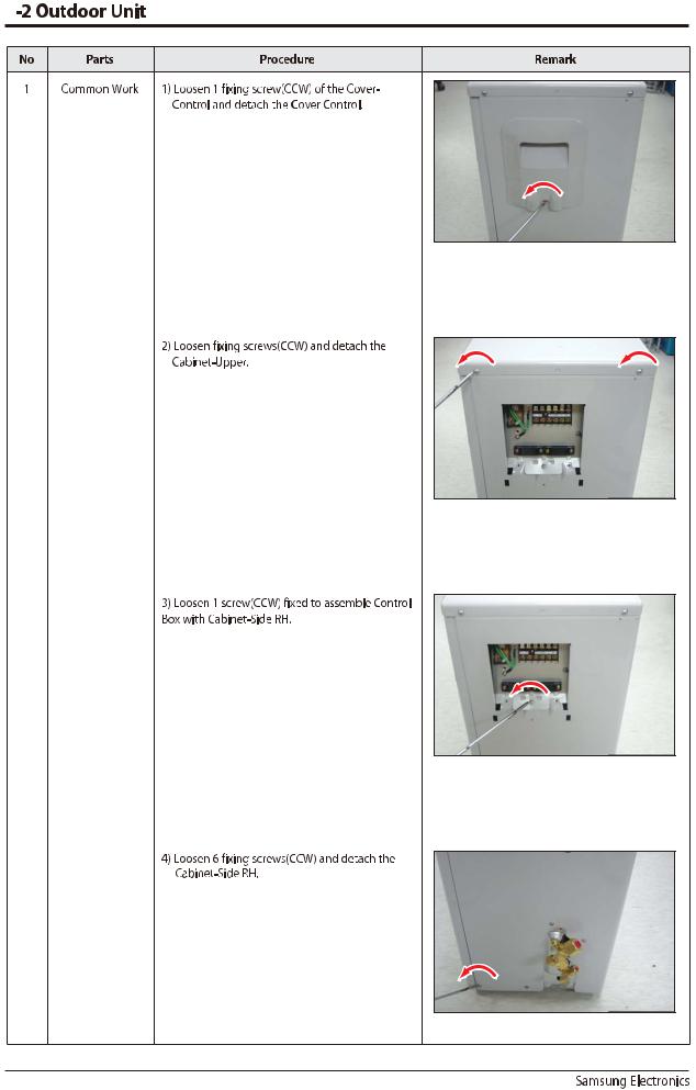
4 |
PBA |
1) Unfasten the screw. |
|
2) Cut the cable tie.
3)Loosen the terminal block wires. (Total 4EA: #N(T)-2EA, #2-TEA, #3-TEA)
Caution:
The terminal is locking type.
So, when you separate terminals, pull pressing the button.
Button
3-4 |
Samsung Electronics |
Operating Instructions and Installation
No |
Parts |
Procedure |
Remark |
|
|
|
|
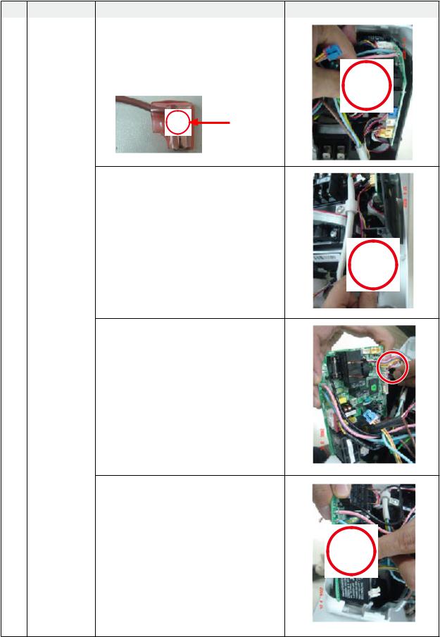
4 |
PBA |
4) Loosen the Motor Feedback connector(CN44). |
|
|
|
Caution: |
|
|
|
When you separate the connector, |
|
|
|
pull pressing the locking button. |
|
5)Loosen the Humidity sensor connector(CN42).
Option connector.
Caution:
When you separate the connector, pull pressing the locking button.
6)Loosen the MPI connector(CN81).
Option connector.
Caution:
When you separate the connector, pull pressing the locking button.
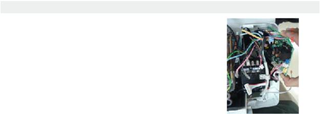
7) Loosen the Relay #4 blue-connector(RY71).
Caution:
The terminal is locking type.
So, when you separate terminals, pull pressing the button.
Button
Samsung Electronics |
3-5 |
Operating Instructions and Installation
No |
Parts |
Procedure |
Remark |
|
|
|
|
4 |
PBA |
8) Loosen the Relay #3 red-connector(RY71). |
|
|
|
Caution: |
|
|
|
The terminal is locking type. |
|
|
|
So, when you separate terminals, |
|
|
|
pull pressing the button. |
|
Button
9) Loosen the Step motor connector.
Caution:
When you separate the connector, pull pressing the locking button.
10) Loosen the Thermistor wire connector(CN43).
Caution:
When you take off the PBA, don’t touch the components.
Please hold the PBA both side.
11) Loosen the Motor connector(CN71).
Caution:
When you separate the connector, pull pressing the locking button.
3-6 |
Samsung Electronics |
|
|
|
Operating Instructions and Installation |
|
|
|
|
No |
Parts |
Procedure |
Remark |
|
|
|
|
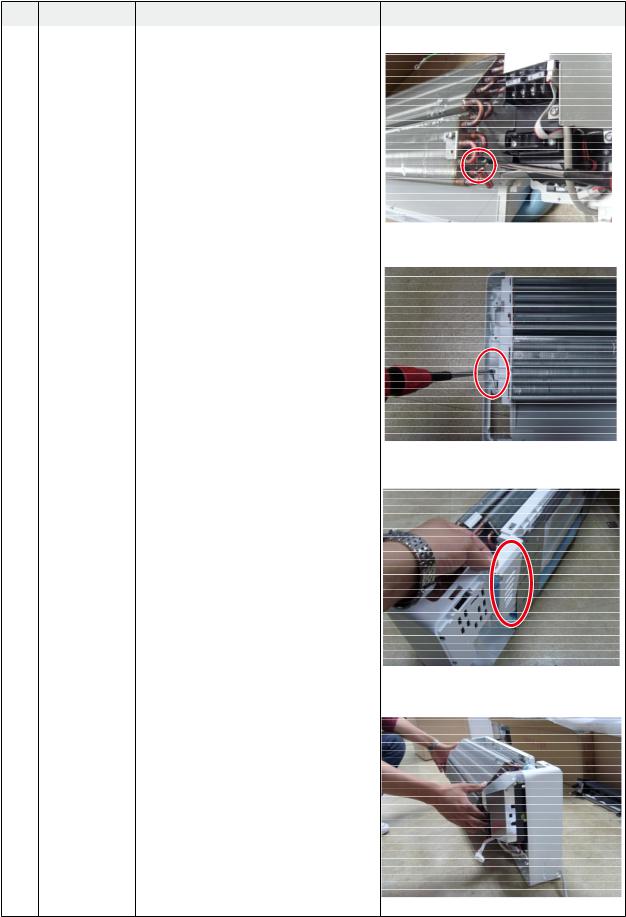
4 |
PBA |
12) Take off the main PBA from the ASS’Y |
|
|
|
Control in. |
|
|
|
Caution: |
|
|
|
When you take off the PBA, don’t touch |
|
|
|
the components. |
|
|
|
Please hold the PBA both side. |
|
|
|
|
|
Samsung Electronics |
3-7 |
Operating Instructions and Installation
No |
Parts |
Procedure |
Remark |
|
|
|
|
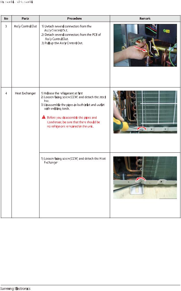
5 |
EVAPORATOR |
1) Unfasten the screw at the right side. |
|
|
|
(use + Screw Driver) |
|
2)Unfasten the screw at the left side. (use + Screw Driver)
3) Detach the HOLDER PIPE.
4)Take off the EVAPORATOR from the main frame.
3-8 |
Samsung Electronics |
|
|
|
Operating Instructions and Installation |
|
|
|
|
No |
Parts |
Procedure |
Remark |
|
|
|
|
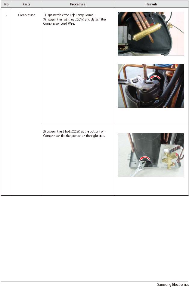
6 |
FAN MOTOR |
1) Unfasten the screw in the HOLDER-EVAP on the |
|
|
& |
left side of evaporator.(use + Screw Driver) |
|
|
CROSS FAN |
|
|
2)unfasten the 3 points screws in the CASECONTROL, and then detach the CASE. (use + Screw Driver)
3) unfasten the screw a little.(use + Screw Driver)
4)Lift up the evaporator slightly and pull the CROSS-FAN to the left side.
Samsung Electronics |
3-9 |
3
3-10

3-11
3-12
3-13
3-14

6.Electrical Parts List
INDOOR MAIN PCB(DB93-07499B)
LOCATION |
CODE |
DESC_SPEC |
Q'TY |
|
|
|
|
D701 |
0402-000012 |
DIODE-RECTIFIER;UF4007,1KV,1A,DO-41,TP |
1 |
|
|
|
|
D4201 |
0402-000137 |
DIODE-RECTIFIER;1N4007,1KV,1A,DO-41,TP |
1 |
|
|
|
|
D4202 |
0402-001194 |
DIODE-RECTIFIER;UG2D,200V,2A,-,TP |
1 |
|
|
|
|
BD4201 |
0402-001298 |
DIODE-BRIDGE;DF06S,600V,1A,SMD-4,TP |
1 |
|
|
|
|
ZD4201 |
0403-000252 |
DIODE-ZENER;BZX84C3V6,3.4-3.8V,350MW,SOT-23,TP |
1 |
|
|
|
|
ZD4203 |
0403-000258 |
DIODE-ZENER;BZX84C5V6,5.6,225mW,SOT-23,TP |
1 |
|
|
|
|
ZD4202 |
0403-001285 |
DIODE-ZENER;BZX84-C11,10.4-11.6V,350mW,SOT-23,TP |
1 |
|
|
|
|
Q2321,Q401 |
0501-000534 |
TR-SMALL SIGNAL;2SC2412K,NPN,200mW,SOT-23,TP,180- |
2 |
|
|
|
|
Q6103 |
0501-002296 |
TR-SMALL SIGNAL;MMST2907A,PNP,200MW,SMT3,TP,100-3 |
1 |
|
|
|
|
Q6101,Q6102 |
0504-000127 |
TR-DIGITAL;FJV3102RMTF,NPN,200MW,10K/10K,SOT-23,T |
2 |
|
|
|
|
Q4201 |
0504-001064 |
TR-DIGITAL;DTC114EKA,NPN,200mW,10K/10K,SOT-23,TP |
1 |
|
|
|
|
IC05,IC06,IC07 |
0506-000175 |
TR-ARRAY;2003,NPN,7,1W,SOP-16,ST,1000 |
3 |
|
|
|
|
PC2321 |
0604-001003 |
PHOTO-COUPLER;TR,50-150%,200mW,DIP-4,ST |
1 |
|
|
|
|
PC4201 |
0604-001038 |
PHOTO-COUPLER;TR,130-260%,200mW,DIP-4,ST |
1 |
|
|
|
|
IC361 |
1103-001175 |
93LC56,128x16,SOP,8P,5x4mm,2.5/6.0V,-40to+85C |
1 |
|
|
|
|
IC4202 |
1203-000274 |
IC-POSI.FIXED REG.;7805,TO-220,3P,-,PLASTIC,4.8/5 |
1 |
|
|
|
|
IC4201 |
1203-002545 |
IC-PWM CONTROLLER;266,DIP,8P,300MIL,PLASTIC,-0.3/ |
1 |
|
|
|
|
IC0102 |
1203-003334 |
IC-RESET;S-801,SOT-23,5P,2.9x1.6mm,PLASTIC,3.716/ |
1 |
|
|
|
|
VA71 |
1405-000160 |
VARISTOR;680V,4500A,17.5x6.5mm,TP,INR14D681KORSY |
1 |
|
|
|
|
R4204,R4205 |
2002-001104 |
R-COMPOSITION;12Mohm,5%,1/2W,AA,TP,3.4x9mm |
2 |
|
|
|
|
R4203 |
2003-000448 |
R-METAL OXIDE(S);100Kohm,5%,2W,AA,TP,4x12mm |
1 |
|
|
|
|
R4206 |
2007-000074 |
R-CHIP;100ohm,5%,1/10W,TP,1608 |
1 |
|
|
|
|
R2102,R2104,R2106 |
2007-000076 |
R-CHIP;330ohm,5%,1/10W,TP,1608 |
3 |
|
|
|
|
R4202 |
2007-000077 |
R-CHIP;470ohm,5%,1/10W,TP,1608 |
1 |
|
|
|
|
R6107,R6106,R0101 |
2007-000078 |
R-CHIP;1Kohm,5%,1/10W,TP,1608 |
8 |
,R403,R404,R405,R2 |
|
|
|
322,R2323 |
|
|
|
R6103,R6104 |
2007-000080 |
R-CHIP;2Kohm,5%,1/10W,TP,1608 |
2 |
|
|
|
|
R4201 |
2007-000084 |
R-CHIP;4.7Kohm,5%,1/10W,TP,1608 |
1 |
|
|
|
|
R2321,R402 |
2007-000084 |
R-CHIP;4.7Kohm,5%,1/10W,TP,1608 |
2 |
|
|
|
|
R401,R6601 |
2007-000087 |
R-CHIP;6.8Kohm,5%,1/10W,TP,1608 |
2 |
|
|
|
|
R301,R302,R406,R5 |
2007-000090 |
R-CHIP;10Kohm,5%,1/10W,TP,1608 |
6 |
01,R6105,R6602 |
|
|
|
R361,R362 |
2007-000097 |
R-CHIP;47Kohm,5%,1/10W,TP,1608 |
2 |
|
|
|
|
R2107 |
2007-000097 |
R-CHIP;47Kohm,5%,1/10W,TP,1608 |
0 |
|
|
|
|
R0102 |
2007-000109 |
R-CHIP;1Mohm,5%,1/10W,TP,1608 |
1 |
|
|
|
|
R303,R305,R306 |
2007-000116 |
R-CHIP;120ohm,5%,1/10W,TP,1608 |
3 |
|
|
|
|
R6108 |
2007-000119 |
R-CHIP;560ohm,5%,1/10W,TP,1608 |
1 |
|
|
|
|
R4207 |
2007-000124 |
R-CHIP;2.2Kohm,5%,1/10W,TP,1608 |
1 |
|
|
|
|
R4208 |
2007-000312 |
R-CHIP;10ohm,5%,1/4W,TP,3216 |
1 |
|
|
|
|
R201,R202,R203,R2 |
2007-000944 |
R-CHIP;47Kohm,5%,1/4W,TP,3216 |
8 |
04,R205,R206,R207, |
|
|
|
R208 |
|
|
|
|
|
|
|
6-1 |
Samsung Electronics |

INDOOR MAIN PCB(DB93-07499B )(CONT.)
LOCATION |
CODE |
|
|
|
DESC_SPEC |
|
|
|
|
Q'TY |
||
|
|
|
|
|
|
|
|
|||||
R201,R202,R203,R204,R2 |
2007-000944 |
R-CHIP;47Kohm,5%,1/4W,TP,3216 |
|
|
|
|
8 |
|||||
05,R206,R207,R208 |
|
|
|
|
|
|
|
|
|
|
|
|
R2103,R2105 |
2007-001068 |
R-CHIP;6.8Kohm,1%,1/10W,TP,1608 |
|
|
|
|
2 |
|||||
|
|
|
|
|
|
|
|
|||||
C4202 |
2201-000983 |
C-CERAMIC,DISC;1NF,10%,2KV,7.5mm |
|
|
|
|
1 |
|||||
|
|
|
|
|
|
|
|
|||||
C701 |
2201-000983 |
C-CERAMIC,DISC;1NF,10%,2KV,7.5mm |
|
|
|
|
0 |
|||||
|
|
|
|
|
||||||||
C4203,C4204 |
2201-000987 |
C-CERAMIC,DISC;2.2NF,20%,400V,Y5U,BK,12.5X6MM,10 |
|
2 |
||||||||
|
|
|
|
|
|
|
||||||
C4205 |
2201-002193 |
C-CERAMIC,DISC;0.082nF, 10%,3000V,5mm |
|
|
|
1 |
||||||
|
|
|
|
|
|
|
|
|||||
C361,C401,C2322,C2323 |
2203-000257 |
C-CER,CHIP;10nF,10%,50V,X7R,TP,1608 |
|
|
|
|
6 |
|||||
,C6101,C6102 |
|
|
|
|
|
|
|
|
|
|
|
|
C301,C302,C305, |
2203-000440 |
C-CER,CHIP;1nF,10%,50V,X7R,TP,1608,- |
|
|
|
|
5 |
|||||
C402,C509 |
|
|
|
|
|
|
|
|
|
|
|
|
C0101,C0102,C0103,C01 |
2203-005249 |
C-CER,CHIP;100nF,10%,50V,X7R,TP,1608,- |
|
|
|
17 |
||||||
04,C0105,C0106,C0107, |
|
|
|
|
|
|
|
|
|
|
|
|
C2102,C2103,C403,C232 |
|
|
|
|
|
|
|
|
|
|
|
|
1,C4201,C4206,C4207,K |
|
|
|
|
|
|
|
|
|
|
|
|
C46,KC47,C6601 |
|
|
|
|
|
|
|
|
|
|
|
|
C2101 |
2203-005249 |
C-CER,CHIP;100nF,10%,50V,X7R,TP,1608,- |
|
|
|
1 |
||||||
|
|
|
|
|
|
|||||||
XC71,XC72 |
2301-001220 |
C-FILM,LEAD-PPF;100nF,10%,275V,BK,18x6x12,15 |
|
|
2 |
|||||||
|
|
|
|
|||||||||
CR71 |
2301-001363 |
C-FILM,LEAD-PPF;2000nF,+10-5%,450V,BK,38x18x30mm,3 |
1 |
|||||||||
|
|
|
|
|
|
|
||||||
CE4205 |
2401-000038 |
C-AL;470uF,20%,25V,GP,TP,85 |
10x12.5mm,5mm |
|
|
1 |
||||||
|
|
|
|
|
|
|
||||||
CE4204 |
2401-000151 |
C-AL;1000uF,20%,25V,GP,TP,85 |
10x20,5mm |
|
|
1 |
||||||
|
|
|
|
|
|
|
|
|||||
CE6101 |
2401-002094 |
C-AL;47uF,20%,25V,GP,TP,85 |
5x11,2.5mm |
|
|
|
1 |
|||||
|
|
|
|
|
|
|
||||||
CE4201,CE4202 |
2401-004330 |
C-AL;22 F,20%,500V,-,TP,12.5X25,7.5mm |
|
|
|
2 |
||||||
|
|
|
|
|
|
|||||||
L4201 |
2702-001118 |
INDUCTOR-RADIAL;5000uH,10%,8.0x11.0mm |
|
|
1 |
|||||||
|
|
|
|
|
|
|||||||
X0101 |
2802-001179 |
RESONATOR-CERAMIC;4MHZ,0.5%,BK,8X3X5.5MM |
|
|
1 |
|||||||
|
|
|
|
|
|
|
|
|
||||
BZ6101 |
3002-001129 |
BUZZER-PIEZO;85DB,-,-,2KHZ,- |
|
|
|
|
|
1 |
||||
|
|
|
|
|
|
|
|
|
|
|||
SS71 |
3502-000115 |
SSR;12Vdc,-,2A,1mS,1mS |
|
|
|
|
|
|
1 |
|||
|
|
|
|
|||||||||
F701-1 |
3601-000263 |
F U S E - C A R T R I D G E ; 2 5 0 V , 3 . 1 5 A , S L O W - |
1 |
|||||||||
|
|
BLOW,GLASS,5.2x20mm |
|
|
|
|
|
|
|
|||
F702 |
3601-001209 |
FUSE-RADIAL LEAD;250V,1A,TIME-LAG,-,8.5x8mm |
|
|
1 |
|||||||
|
|
|
|
|
|
|
|
|
|
|
|
|
CN72 |
3711-000262 |
C |
O |
N |
N |
E |
C |
T |
O |
R |
- |
1 |
|
|
HEADER;1WALL,3P,1R,7.92MM,STRAIGHT,SN,W |
|
|
|
|||||||
CN44 |
3711-000879 |
HEADER-BOARD TO CABLE;BOX,3P,1R,2.5mm,STRAIGHT,SN |
1 |
|||||||||
|
|
|
|
|||||||||
CN6601 |
3711-000941 |
HEADER-BOARD TO CABLE;BOX,4P,1R,2.5mm,STRAIGHT,SN |
0 |
|||||||||
|
|
|
|
|
|
|
|
|
|
|
||
CN22 |
DB39-01194A |
CONNECT WIRE |
|
|
|
|
|
|
|
1 |
||
|
|
|
|
|
|
|
|
|||||
PCB |
DB41-00752A |
VIVALDI INDOOR INVERTER PCB FR-4 |
|
|
|
|
0 |
|||||
|
|
|
|
|
|
|
|
|||||
PCB |
DB41-00794A |
VIVALDI INDOOR INVERTER PCB FR-4 |
|
|
|
|
1 |
|||||
|
|
|
|
|
|
|
|
|
||||
F701 |
DB61-00924A |
HOLDER-FUSE;500V,-,100M |
|
|
|
|
|
1 |
||||
|
|
|
|
|
|
|
|
|
|
|
||
485 SUB PBA |
DB93-04257C |
INDOOR SUB PBA |
|
|
|
|
|
|
|
1 |
||
|
|
|
|
|||||||||
CN91(1-8) |
DB93-06896C |
Vivaldi-P/J,190mm,25045TP,SMH250-5HRT,AWG#26,SSEC |
1 |
|||||||||
|
|
|
|
|
|
|
|
|
|
|
||
VA71 |
DB67-00942A |
VARISTOR CAP |
|
|
|
|
|
|
|
1 |
||
|
|
|
|
|
|
|
|
|
|
|
|
|
Samsung Electronics |
6-2 |

3

Electrical Part List
 OUTDOOR MAIN PCB DB93-07112K (AQV18E**),DB93-07112L(AQV24E**)
Design location |
CODE |
DESC_SPEC |
18K |
24K |
|
|
|
|
|
D451,D452,D453,D454 |
0401-000133 |
DIODE-SWITCHING;RLS4148,75V,150mA,LL-34,TP |
4 |
4 |
D103,D104,D105,D106 |
0402-001427 |
DIODE-RECTIFIER;ES1D,200V,1A,DO-214AC,TP |
4 |
4 |
D102,D401,D402,D403 |
0402-001429 |
DIODE-RECTIFIER;US1J,600V,1A,DO-214AC,TP |
4 |
4 |
BD01 |
0402-001553 |
DIODE-BRIDGE;GBPC3506W,600V,35A,SQUARE-4,BK |
1 |
1 |
ZD451,ZD452,ZD501, |
0403-000258 |
DIODE-ZENER;MMBZ5232B,5%,225mW,SOT-23,TP |
4 |
4 |
ZD502 |
|
|
|
|
CD31,CD32 |
0406-001109 |
DIODE-TVS;SAC5.0,7.6/-/-V,500W,DO-15 |
2 |
2 |
D201 |
0407-000123 |
DIODE-ARRAY;DAN202K,80V,100mA,CA2-3,SOT-23,TP |
1 |
1 |
Q904,Q905,Q906,Q907 |
0504-000001 |
TR-DIGITAL;DTA114EKA,PNP,200mW,10K/10K,SOT-23,TP |
4 |
4 |
Q801 |
0504-000127 |
TR-DIGITAL;FJV3102RMTF,NPN,200MW,10K/10K,SOT-23,T |
1 |
1 |
Q902 |
0504-000127 |
TR-DIGITAL;FJV3102RMTF,NPN,200MW,10K/10K,SOT-23,T |
1 |
0 |
IC51,IC52,IC53,IC54,IC55 |
0506-000175 |
TR-ARRAY;2003,NPN,7,1W,SOP-16,ST,1000 |
6 |
6 |
,IC72 |
|
|
|
|
Q803 |
0508-001154 |
TR-IGBT; -,600V,80A,-,195W,TO-3P |
1 |
1 |
IC12,IC61,IC62 |
0604-001172 |
PHOTO-COUPLER;TR,100-300,200mW,SOP,TP |
3 |
3 |
IC30 |
0801-000393 |
IC-CMOS LOGIC;74HC86,OR GATE,SOP,14P,150MIL,QUAD,S |
1 |
1 |
IC20 |
1006-001371 |
IC-BUS TRANSCEIVER |
1 |
1 |
IC21 |
1202-000104 |
IC-VOLTAGE COMP.;393,SOP,8P,150MIL,DUAL,36V,CMO |
1 |
1 |
IC16,IC19 |
1203-000274 |
IC-POSI.FIXED REG.;7805,TO-220,3P,-,PLASTIC,4.8/5 |
2 |
2 |
IC13 |
1203-002948 |
IC-POSI.ADJUST REG.;TL431ACD,SOP,8P,4.9X3.9MM,PLA |
1 |
1 |
IC59 |
1203-003334 |
IC-RESET;S-801,SOT-23,5P,2.9x1.6mm,PLASTIC,3.716/ |
1 |
1 |
IC11 |
1203-003527 |
IC-PWM CONTROLLER;TOP243,DIP,7P,9.83x6.6mm,PLASTIC |
1 |
1 |
R107 |
2003-000708 |
R-METAL OXIDE(S);47ohm,5%,1W,AA,TP,3.3x9mm |
1 |
1 |
R101 |
2003-000855 |
R-METAL OXIDE(S);47Kohm,5%,3W,AA,TP,6x16mm |
1 |
1 |
R110 |
2003-002246 |
R-METAL OXIDE(S);620ohm,5%,1W,AA,TP,2.4x6.4mm |
1 |
1 |
R001 |
2006-001168 |
R-CEMENT;200ohm,5%,10W,CB,BK,15.7x11.5x34.2mm |
1 |
1 |
R421 |
2006-001145 |
ASSY-R CEMENT |
1 |
1 |
R401,R402,R403,R404,R |
2007-000074 |
R-CHIP;100ohm,5%,1/10W,TP,1608 |
6 |
6 |
405,R406 |
|
|
|
|
R504,R505,R506,R507,R |
2007-000076 |
R-CHIP;330ohm,5%,1/10W,TP,1608 |
7 |
7 |
553,R606,R607 |
|
|
|
|
R323,R342,R808 |
2007-000077 |
R-CHIP;470ohm,5%,1/10W,TP,1608 |
3 |
3 |
R103,R512,R557,R559,R |
2007-000078 |
R-CHIP;1Kohm,5%,1/10W,TP,1608 |
6 |
6 |
601,R604 |
|
|
|
|
R205,R208 |
2007-000080 |
R-CHIP;2Kohm,5%,1/10W,TP,1608 |
2 |
2 |
R104 |
2007-000082 |
R-CHIP;3.3Kohm,5%,1/10W,TP,1608 |
1 |
1 |
R324,R325,R327,R328, |
2007-000084 |
R-CHIP;4.7Kohm,5%,1/10W,TP,1608 |
5 |
5 |
R407 |
|
|
|
|
R315 |
2007-000097 |
R-CHIP;47Kohm,5%,1/10W,TP,1608 |
1 |
1 |
R914 |
2007-000087 |
R-CHIP;6.8Kohm,5%,1/10W,TP,1608 |
1 |
0 |
R302,R303,R304,R305, |
2007-000090 |
R-CHIP;10Kohm,5%,1/10W,TP,1608 |
22 |
22 |
R306,R316,R509,R552, |
|
|
|
|
R554,R555,R556,R558, |
|
|
|
|
R560,R561,R562,R563, |
|
|
|
|
R566,R573,R574,R805, |
|
|
|
|
R916,R917 |
|
|
|
|
R913 |
2007-000090 |
R-CHIP;10Kohm,5%,1/10W,TP,1608 |
1 |
0 |
R510 |
2007-000109 |
R-CHIP;1Mohm,5%,1/10W,TP,1608 |
1 |
1 |
R551 |
2007-000109 |
R-CHIP;1Mohm,5%,1/10W,TP,1608 |
1 |
1 |
R102 |
2007-000111 |
R-CHIP;6.8ohm,5%,1/10W,TP,1608 |
1 |
1 |
R408,R409,R410 |
2007-000113 |
R-CHIP;33ohm,5%,1/10W,TP,1608 |
3 |
3 |
Samsung Electronics |
6-4 |

Electrical Part List
OUTDOOR MAIN PCB DB93-07112K (AQV18E**),DB93-07112L(AQV24E**),(CONT.)
Design location |
CODE |
DESC_SPEC |
18K |
24K |
|
|
|
|
|
R301 |
2007-000116 |
R-CHIP;120ohm,5%,1/10W,TP,1608 |
1 |
1 |
R115 |
2007-000385 |
R-CHIP;14.3Kohm,1%,1/4W,TP,3216 |
1 |
1 |
R502,R515 |
2007-000455 |
R-CHIP;18Kohm,1%,1/10W,TP,1608 |
2 |
2 |
R706,R707,R708 |
2007-000512 |
R-CHIP;2.4Kohm,5%,1/10W,TP,1608 |
3 |
3 |
R807 |
2007-000553 |
R-CHIP;20ohm,5%,1/4W,TP,3216 |
1 |
1 |
R503,R514 |
2007-000614 |
R-CHIP;24Kohm,1%,1/10W,TP,1608 |
2 |
2 |
R112,R113,R114 |
2007-000924 |
R-CHIP;470Kohm,1%,1/4W,TP,3216 |
3 |
3 |
R412 |
2007-000929 |
R-CHIP;470ohm,1%,1/10W,TP,1608 |
1 |
1 |
R806 |
2007-000950 |
R-CHIP;47ohm,5%,1/4W,TP,3216 |
1 |
1 |
R511,R910,R911,R912 |
2007-000965 |
R-CHIP;5.1Kohm,5%,1/10W,TP,1608 |
4 |
4 |
R907,R908,R909 |
2007-001179 |
R-CHIP;8.2Kohm,5%,1/10W,TP,1608 |
3 |
3 |
R900,R901,R902,R903,R |
2007-001318 |
R-CHIP;1Kohm,5%,1/4W,TP,3216 |
7 |
7 |
904,R905,R906 |
|
|
|
|
R201,R202,R206,R207 |
2007-002667 |
R-CHIP;90.9Kohm,1%,1/4W,TP,3216 |
4 |
4 |
R106,R203,R204 |
2007-007342 |
R-CHIP;1.82Kohm,1%,1/10W,TP,1608 |
3 |
3 |
R105 |
2007-007445 |
R-CHIP;9.09Kohm,1%,1/10W,TP,1608 |
1 |
1 |
R116,R117,R118 |
2007-008261 |
R-CHIP;150Kohm,1%,1/2W,TP,5025 |
3 |
3 |
C307,C308,C309,C310 |
2201-000154 |
C-CERAMIC,DISC;10NF,+80-20%,2KV,Y5P,TP,20X5MM,7.5 |
4 |
4 |
C105,C106 |
2201-000322 |
C-CERAMIC,DISC;2.2NF,10%,2KV,Y5P,TP,13X5MM,10 |
2 |
2 |
C903 |
2201-000322 |
C-CERAMIC,DISC;2.2NF,10%,2KV,Y5P,TP,13X5MM,10 |
1 |
0 |
C411,C412,C413,C414, |
2203-000125 |
C-CER,CHIP;1.2nF,10%,50V,X7R,TP,1608,- |
6 |
6 |
C415,C416 |
|
|
|
|
C201,C203,C204,C205, |
2203-000257 |
C-CER,CHIP;10nF,10%,50V,X7R,TP,1608,- |
18 |
18 |
C301,C451,C452,C453, |
|
|
|
|
C454,C567,C603,C607, |
|
|
|
|
C801,C900,C901,C902, |
|
|
|
|
C907,C908 |
|
|
|
|
C108 |
2203-001414 |
C-CER,CHIP;330NF,10%,50V,X7R,TP,2012 |
1 |
1 |
C318,C319,C320,C321 |
2203-002002 |
C-CER,CHIP;33pF,5%,50V,NPO,BK,1608,- |
4 |
4 |
C109,C112,C116,C117, |
2203-005249 |
C-CER,CHIP;100nF,10%,50V,X7R,TP,1608,- |
47 |
47 |
C121,C202,C302,C303, |
|
|
|
|
C304,C305,C306,C404, |
|
|
|
|
C405,C406,C407,C408, |
|
|
|
|
C409,C410,C417,C418, |
|
|
|
|
C501,C502,C503,C504, |
|
|
|
|
C505,C506,C507,C508, |
|
|
|
|
C509,C510,C511,C512, |
|
|
|
|
C513,C553,C554,C555, |
|
|
|
|
C556,C560,C561,C563, |
|
|
|
|
C565,C568,C570,C575, |
|
|
|
|
C576,C706,C3011 |
|
|
|
|
C419,C420 |
2203-002398 |
C-CER,CHIP;22nF,10%,50V,X7R,1608 |
2 |
2 |
C113,C122,C802 |
2203-005261 |
C-CER,CHIP;1000nF,10%,25V,X7R,-,3216 |
3 |
3 |
C904 |
2203-006104 |
C-CER,CHIP;1000nF,10%,50V,X7R,3225 |
1 |
0 |
C008 |
2301-000141 |
C-FILM,LEAD-PEF;10nF,10%,630V,TP,16x11x7.5mm,5 |
1 |
1 |
C422,C803 |
2306-000123 |
C-FILM,LEAD-PPF;100nF,5%,630V,BK,26x16.5x8.5,2/ |
2 |
2 |
|
|
100nF,5%,630V,17x12x6,15mm |
|
|
C123 |
2401-000303 |
C-AL;100uF,20%,25V,GP,TP,6.3x11,5 |
1 |
1 |
C552,C559,C562,C564, |
2401-000493 |
C-AL;10uF,20%,50V,LZ,TP,5x11mm,5mm ,105 |
7 |
7 |
C569,C574,C577 |
|
|
|
|
C906 |
2401-000493 |
C-AL;10uF,20%,50V,LZ,TP,5x11mm,5mm ,105 |
1 |
0 |
6-5 |
Samsung Electronics |

Electrical Part List
OUTDOOR MAIN PCB DB93-07112K (AQV18E**),DB93-07112L(AQV24E**)(CONT.)
Design location |
CODE |
|
|
DESC_SPEC |
|
|
|
18K |
I 24K |
|
|
|
|
|
|
|
|
|
|||
C905 |
2401-000880 |
C-AL;220uF,20%,50V,WT,TP,10x16mm,5m |
|
|
1 |
|
0 |
|||
C114,C421 |
2401-002274 |
C-AL;220uF,20%,35V,WT,TP,8x11.5mm,5 ,105 |
|
|
2 |
|
2 |
|||
C107,C118,C401, |
2401-002438 |
C-AL;47 F,20%,50V,WT,TP,6.3x11,5mm,105 |
|
|
5 |
|
5 |
|||
C402,C403 |
|
|
|
|
|
|
|
|
|
|
C104 |
2401-003541 |
C-AL;10uF,20% ,450V,WT,TP,12.5x20mm,5 |
|
|
1 |
|
1 |
|||
C119,C805 |
2401-003585 |
C-AL;220uF,20%,35V,WT,TP,8x11.5mm,5 ,105 |
|
|
2 |
|
2 |
|||
C110 |
2401-001374 |
C-AL;470uF,20%,16V,WT,TP,10x12.5mm,5mm |
|
|
1 |
|
1 |
|||
C101,C102,C103 |
2401-003740 |
C-AL;560uF,20%,400V,WT,BK,35x50mm,10 ,105 |
|
3 |
|
3 |
||||
XTAL51 |
2802-001179 |
RESONATOR-CERAMIC;4MHZ,0.5%,BK,8X3X5.5MM |
|
1 |
|
1 |
||||
XTAL |
2802-001198 |
RESONATOR-CERAMIC;10MHZ,0.5%,BK,8X3X5.5MM |
|
1 |
|
1 |
||||
RY03,RY04 |
3501-001154 |
R |
E |
L |
A |
Y |
- |
0 |
|
2 |
|
|
MINIATURE;12Vdc,200mW,3000mA,1FormA,10mS,10m |
|
|
|
|
||||
RY05 |
3501-001154 |
R |
E |
L |
A |
Y |
- |
1 |
|
1 |
|
|
MINIATURE;12Vdc,200mW,3000mA,1FormA,10mS,10m |
|
|
|
|
||||
RY31 |
3501-001248 |
RELAY-MINIATURE;12V,-,11.7MA,DPDT,4MS,4MS |
|
1 |
|
1 |
||||
RY01 |
3501-001268 |
RELAY-POWER;12V,0.9W,25000mA,SPST,20mS,10mS |
|
1 |
|
1 |
||||
CN00 |
3711-003843 |
HEADER-BOARD TO CABLE |
|
|
|
1 |
|
1 |
||
CN71 |
3711-004019 |
CONNECTOR-HEADER |
|
|
|
1 |
|
0 |
||
CN34 |
3711-004182 |
CONNECTOR-HEADER;BOX,10P,1R,2MM,STRAIGHT,SN,NTR |
|
1 |
|
1 |
||||
CN61 |
3711-004484 |
CONNECTOR-HEADER;BOX,5P,1R,2mm,STRAIGHT,SN |
|
1 |
|
1 |
||||
REACTOR01, |
3712-001139 |
CONNECTOR-TERMINAL;TAB,MALE,-,6.35X0.8MM |
|
2 |
|
2 |
||||
REACTOR02 |
|
|
|
|
|
|
|
|
|
|
Q901 |
DB13-00003A |
IC DRIVER GATE;-,SOT-23,-,-,1P,1P,0.2mm,2.93x1.3mm |
|
1 |
|
0 |
||||
PT02 |
DB26-00075A |
TRANS PULSE;PT_50,MH080FXEA4,10,65.5,8~14,EI2218, |
|
1 |
|
1 |
||||
IC451,IC452 |
DB32-00173A |
S E N S O R |
|
M A G - C T |
S E N S O R ; A S C 7 1 2 , 5 H P |
2 |
|
2 |
||
|
|
INVERTER,-,-40~150 |
|
|
|
|
|
|
||
PCB MAIN |
DB41-00778A |
PCB |
|
|
|
|
|
1 |
|
1 |
IC01 |
DB91-00532E |
XSA OUTDOOR Inv Micom,MN103SFA7K,80P, ROM Size: |
0 |
|
1 |
|||||
|
|
256K bytes |
|
|
|
|
|
|
|
|
IC01 |
DB09-00517A |
IC MICOM;MN103FA7K,-,80P,+5V,10 MHz,Flash Memory, |
|
0 |
|
1 |
||||
IC01 |
DB91-00744A |
OUTDOOR Inv Micom,MN103SFA7K,80P, ROM Size: 256K |
1 |
|
0 |
|||||
|
|
bytes |
|
|
|
|
|
|
|
|
IC01 |
DB09-00517A |
IC MICOM;MN103FA7K,-,80P,+5V,10 MHz,Flash Memory, |
|
1 |
|
0 |
||||
IC50 |
DB91-00945A |
ASSY MICOM 09R FORTE,VIVACE, MONTBLANC 18K24K |
|
1 |
|
1 |
||||
IC50 |
DB09-00338A |
IC MICOM;MB90F823,-,80 P,5 V,24 MHz,STM-0493-OA,- |
|
1 |
|
1 |
||||
IC701 |
DB91-00845A |
EEPROM DATA |
|
|
|
1 |
|
0 |
||
IC701 |
1103-001038 |
IC-EEPROM;93LC66,4KBIT,256X16BIT,SOP,8P,5X4MM,-,2 |
|
1 |
|
0 |
||||
IC701 |
DB91-00844A |
EEPROM DATA |
|
|
|
0 |
|
1 |
||
IC701 |
1103-001038 |
IC-EEPROM;93LC66,4KBIT,256X16BIT,SOP,8P,5X4MM,-,2 |
|
0 |
|
1 |
||||
L/W COMM 485 |
DB93-04333B |
CONNECT WIRE |
|
|
|
1 |
|
1 |
||
C/W COMP |
DB93-04335B |
CONNECT WIRE |
|
|
|
1 |
|
1 |
||
YEL,BLU ,RED |
DB93-04338A |
CONNECT WIRE |
|
|
|
0 |
|
1 |
||
L/W EARTH |
DB93-04344A |
CONNECT WIRE |
|
|
|
1 |
|
1 |
||
C/W 4 WAY |
DB93-04349A |
CONNECT WIRE |
|
|
|
1 |
|
1 |
||
L/W POWER L_1 |
DB93-04351A |
CONNECT WIRE |
|
|
|
1 |
|
1 |
||
L/W POWER N |
DB93-04351B |
CONNECT WIRE |
|
|
|
1 |
|
1 |
||
IC81 |
DB95-00595A |
ASSY-PHOTO COUPLER;MH080FXEA4,- |
|
|
1 |
|
1 |
|||
IPM |
DB95-00954A |
ASSY-IPM MITSUBISHI |
|
|
|
0 |
|
1 |
||
IPM |
DB95-00960A |
ASSY-IPM MITSUBISHI |
|
|
|
1 |
|
0 |
||
D101 |
DB98-16591A |
ASSY-DIODE RECTIFIER;FEP30JP |
|
|
1 |
|
1 |
|||
LED2 |
DB98-16600A |
ASSY-LED GREEN;---------------------------------- |
|
|
1 |
|
1 |
|||
Samsung Electronics |
6-6 |

Electrical Part List
OUTDOOR MAIN PCB DB93-07112K (AQV18E**),DB93-07112L(AQV24E**),(CONT.)
Design location |
CODE |
DESC_SPEC |
18K |
I 24K |
|
|
|
|
|
LED1 |
DB98-16601A |
ASSY-LED RED;---------------------------------- |
1 |
1 |
LED3 |
DB98-16602A |
ASSY-LED YEL;---------------------------------- |
1 |
1 |
CN51 |
DB98-22298A |
ASSY-HOOK WHT;INVERTER,SMAW250A-04,RED |
1 |
1 |
CN50 |
DB98-22299A |
ASSY-HOOK WHT;INVERTER,SMAW250A-04,WHT |
1 |
1 |
CN30 |
DB98-24921A |
ASSY-CONNECTOR;AS-WB670X,SMAW250A-06,WHT |
1 |
1 |
6-7 |
Samsung Electronics |
 Loading...