


INSTALLATION
MANUAL
AQ07X Series
AQ09X Series
Split-type Air Conditioner
(Cooling and Heating)

Safety Precautions
The following safety precautions must be taken when using your air conditioner.
WARNING |
Risk of electric shock. • Can cause injury or death. • Disconnect all |
|
remote electric power supplies before servicing, installing or cleaning. |
||
|
||
|
• This must be done by the manufacturer or its service agent or a similar |
qualified person in order to avoid a hazard.
INSTALLING THE UNIT
POWER SUPPLY LINE, FUSE OR CIRCUIT BREAKER
The unit should not be installed by the user. Ask the dealer or authorized company to install the units except room air conditioners for the U.S.A and Canada area.
If the unit is installed improperly, water leakage, electric shock or fire may result.
Mount with the lowest moving parts at least 2.5 m above the floor or grade level. (If applicable)
The manufacturer does not assume responsibility for accidents or injury caused by an incorrectly installed air conditioner. If you are unsure about installation, contact an installation specialist.
When installing the built-in type air conditioner, keep all electrical cables such as the power cable and the connection cord in pipe, ducts, cable channels e.t.c to protect them against liquids, outside impacts and so on.
If the power cord of this air conditioner is damaged, it must be replaced by the manufacturer, its service agent or similarly qualified persons in order to avoid a hazard.
The unit must be plugged into an independent circuit if applicable or connect the power cable to the auxiliary circuit breaker. An all pole disconnection from the power supply must be incorporated in the fixed wiring with a contact opening of >3mm.
Do not use an extension cord with this product.
If the unit is equipped with a power supply cord and a plug, the plug must be accessible after installation.
The air conditioner must be installed in accordance with national wiring regulations and safety regulations wherever applicable.
E-2

Contents
ˇ PREPARING THE INSTALLATION |
|
Deciding on Where to Install the Air Conditioner .......................................... |
4 |
Air Conditioner and Accessories ................................................................... |
6 |
ˇ INSTALLING THE UNIT |
|
Fixing the Installation Plate ........................................................................... |
7 |
Purging the Unit............................................................................................. |
7 |
Connecting the Assembly Cable ................................................................... |
8 |
Installing and Connecting the Indoor Unit Drain Hose.................................. |
9 |
Installing and Connecting the Outdoor Unit Drain Hose............................... |
9 |
Installing and Connecting the Indoor Unit Assembly Piping ......................... |
10 |
Cutting/Extending the Piping ........................................................................ |
11 |
ˇ COMPLETING THE INSTALLATION |
|
Connecting Up and Purging the Circuit......................................................... |
12 |
Performing Leak Tests................................................................................... |
13 |
Placing the Indoor Unit in Position ................................................................ |
13 |
Fixing the Outdoor Unit in Position ............................................................... |
14 |
Checking and Testing Operations ................................................................. |
14 |
Explaining Operations to the Owner ............................................................. |
15 |
E-3

PREPARING THE INSTALLATION
Deciding on Where to Install the Air Conditioner
When deciding on the location of the air conditioner with the owner, the following restrictions must be taken into account.
General
Do NOT install the air conditioner in a location where it will come into contact with the following elements:
Combustible gases
Saline air
Machine oil
Sulphide gas
Special environmental conditions
If you must install the unit in such conditions, first consult your dealer.
Indoor Unit
There must be no obstacles near the air inlet and outlet.
Install the indoor unit on a surface that can support its weight.
Choose a position that enables the piping and cables to be easily connected to the outdoor unit and the recommended length of 5 metres to be respected (15 metres maximum).
Leave enough clearance beneath the indoor unit to enable the filters to be removed without hindrance.
Maintain sufficient clearance around the indoor unit, as indicated in the diagram on the page opposite.
Make sure that the water dripping from the drain hose runs away correctly and safely.
Install the indoor unit on the wall which is far from the floor by more than 2.5 meters.
Outdoor Unit
The outdoor unit must NEVER be placed on its side or upside down, as the compressor lubrication oil will run into the cooling circuit and seriously damage the unit.
Choose a location that is dry and sunny, but not exposed to direct sunlight or strong winds.
Do not block any passageways or thoroughfares.
Choose a location where the noise of the air conditioner when running and the discharged air do not disturb any neighbours.
Choose a position that enables the piping and cables to be easily connected to the indoor unit and the recommended length of 5 metres to be respected (15 metres maximum).
Install the outdoor unit on a flat, stable surface that can support its weight and does not generate any unnecessary noise and vibration.
Position the outdoor unit so that the air flow is directed towards the outside, as indicated by the arrows on the top of the unit.
Maintain sufficient clearance around the outdoor unit, as indicated in the diagram on the page opposite.
If the outdoor unit is installed at a height, ensure that its base is firmly fixed in position; the maximum height is 7 metres.
Make sure that the water dripping from the drain hose runs away correctly and safely.
CAUTION
You have just purchased a split-type room air conditioner and it has been installed by your installation specialist.
This device must be installed according to the national electrical rules.
Max input power & current is measured according to IEC standard and input power & current is measured according to ISO standard.
E-4
PREPARING THE INSTALLATION
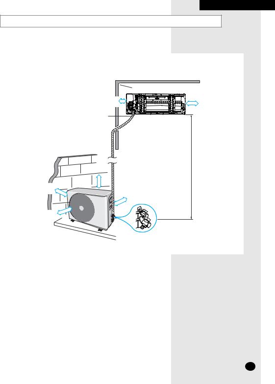
Respect the clearances and maximum lengths indicated in the diagram below when installing the unit.
300 mm or more
Wrap the refrigerant pipes and the drain hose up in the absorbent pad and the vinyl tape, refer to page 13.
|
600 mm |
|
minimum |
|
15 metres |
|
maximum |
300 mm |
300 mm |
minimum |
|
|
minimum |
600 mm |
|
minimum |
|
 300 mm or more
125 mm or more
This drain direction is selectable to left or right.
7 metres maximum
E-5

PREPARING THE INSTALLATION
Air Conditioner and Accessories
The following accessories are supplied with the air conditioner.
The quantities are indicated in parentheses.
Accessories in the Indoor Unit Case
Installation Plate (1) |
|
Remote Control (1) |
||||||||||||||||
|
|
|
|
|
|
|
|
|
|
|
|
|
|
|
|
|
|
|
|
|
|
|
|
|
|
|
|
|
|
|
|
|
|
|
|
|
|
|
|
|
|
|
|
|
|
|
|
|
|
|
|
|
|
|
|
|
|
|
|
|
|
|
|
|
|
|
|
|
|
|
|
|
|
|
|
|
|
|
|
|
|
|
|
|
|
|
|
|
|
|
|
|
|
|
|
|
|
|
|
|
|
|
|
|
|
|
|
|
|
|
|
|
|
|
|
|
|
|
|
|
|
|
|
|
|
|
|
|
|
|
|
|
Batteries for Remote Control (2)
User's Manual and
Installation Manual(1)
GMEMBAIRASTNMANUARUUOENUCALWUZHLDNIASOD'EULANERTNDI'IISLNWPEREISISENINTAISSRSTLTUUTI'URONRÇUNSGUÕCOCETCSIOIONNSES
Accessories in the Outdoor Unit Case
The follow ing connection accessories may be supplied, depending on the option. If they are not supplied, it is recommended that you collect them together before starting to install the air conditioner.
5-wire |
Assembly Cable (1) |
(**07**) |
H05VV-F 5G, 0.75mm2 |
Cable-tie (4)
5-wire |
Assembly Cable (1) |
(**09**) |
H05VV-F 5G, 1.0mm2 |
PE T3 Foam Tube
Insulation (1)
Assembly Piping |
Assembly Piping |
Ø6.35mm (1) |
Ø9.52mm (1) |
Vinyl Tape, |
M4 x 16 Tapped |
Width 50mm (2) |
Screws (6) |
|
|
|
|
|
|
|
|
|
|
|
|
|
|
|
|
|
|
|
|
|
|
|
|
|
|
|
|
|
|
|
|
|
|
|
|
|
|
|
|
|
|
|
|
|
|
|
|
|
|
|
|
|
|
|
|
|
|
|
|
|
|
|
|
|
|
Rubber Leg (4) |
|
|
Drain Hose, |
|
Putty 100g (1) |
|
Drain Plug (1) |
||||
|
|
|
|
|
length 2m (1) |
|
|
|
|
|
|
|
|
|
|
|
|
|
|
|
|
|
|
|
|
The flare nuts are attached to the end of each evaporator in/ out pipe or service valve. Use the nuts w hen connecting the pipe.
The 5-w ire assembly cable is depending on the option. If they are not supplied, Using the standard cable.
The drain plug and rubber leg are only included when the air conditioner is supplied w ithout the assembly piping illustrated below.
E-6

INSTALLING THE UNIT
Fixing the Installation Plate
Before fixing the installation plate to a wall or window frame, you must determine the position of the 65 mm hole through which the cable, piping and hose pass to connect the indoor unit up to the outdoor unit. When facing the air conditioner in position on the wall, the piping and cable can be connected from the:
Right
Left
Rear (right or left)
1Determine the position of the pipe and drain hose hole using the right figure and drill the hole with an inner diameter of 65 mm so that it slants slightly downwards.
2 |
If you are fixing the indoor unit to a... |
Then follow Steps... |
|
|
|
|
Wall |
3. |
|
|
|
|
Window frame |
4 to 6. |
3Fix the installation plate to the wall in a manner appropriate to the weight of the indoor unit.
If you are mounting the plate on a concrete wall with anchor bolts, the anchor bolts must not project by more than 20 mm.
4Determine the positions of the wooden uprights to be attached to the window frame.
5Attach the wooden uprights to the window frame in a manner appropriate to the weight of the indoor unit.
6Using tapped screws, attach the installation plate to the wooden uprights, as illustrated in the last figure opposite.
Installation plate
Pipe hole (Ø65mm)
(Unit : mm)
90 |
90 |
Purging the Unit
On delivery, the indoor unit is loaded with an inert gas. All this gas must therefore be purged before connecting the assembly piping. To purge the inert gas, proceed as follows.
Unscrew the caps at the end of each pipe.
Result: All inert gas escapes from the indoor unit.
To prevent dirt or foreign objects from getting into the pipes during installation, do NOT remove the caps completely until you are ready to connect the piping.
30mm
E-7

INSTALLING THE AIR CONDITIONER
Connecting the Assembly Cable
Indoor Unit |
N 1 |
1 |
2 |
3 |
E |
N1 |
N1 |
2 |
3 |
E |
N1 |
1 |
2 |
3 |
Outdoor Unit |
N 1 |
1 |
2 |
3 |
**Screws on terminal block must not be unscrewed with the torque less than 12 kgf.cm.
The designs and shape are subject to change according to the model.
The outdoor unit is powered from the indoor unit through the assembly cable. If the outdoor unit is more than 5 meters away from the indoor unit, you must extend the cable. The maximum length of the cable is 15 meters.
1Extend the assembly cable if necessary. .
2Remove the cover terminal on the side of the indoor unit.
3Pass the assembly cable through the rear of the indoor unit and connect the assembly cable to terminals as seen in the picture.
 Each wire is labeled with the corresponding terminal number.
4Pass the other end of the cable through the 65mm hole in the wall.
5Close the connector cover tightening the screw carefully.
6Close the cover terminal.
7Remove the terminal board cover on the side of the outdoor unit.
8Connect the cables to the terminals as seen in the picture.
 Each wire is labeled with the corresponding terminal number.
9Connect the earth conductor to the earth terminals.
10Close the terminal board cover tightening the screw carefully.
Specially for Russian and European market, Before installation, the supply authorithy should be consulted to determine the supply system impedance to ensure compliance.
 Power cable specification
Model |
Power cable |
Interconnection cable |
|
|
|
|
|
**07** |
- |
5G, 0.75mm2 |
|
H05VV-F |
|||
|
|
||
**09** |
- |
5G, 1.0mm2 |
|
H05VV-F |
|||
|
|
Connect the power cable to the auxiliary circuit breaker If every pole fails to connect to the power supply, it must
be incorporated in a wire with a contact opening of >3mm.
E-8

INSTALLING THE UNIT
Installing and Connecting the Indoor Unit Drain Hose
Care must be taken when installing the drain hose for the indoor unit to ensure that any condensation water is correctly drained outside. When passing the drain hose through the 65 mm hole drilled in the wall, check that none of the following situations occur.
The hose must |
The end of the drain |
Do NOT bend the |
NOT slope |
hose must NOT be |
hose in different |
upwards. |
placed in water. |
directions. |
5 cm |
less |
Keep a clearance of at least 5 cm between the end of the hose and the ground.
 Ditch
Ditch
Do NOT place the end of the drain hose in a hollow.
To install the drain hose, proceed as follows.
1If necessary, connect the 2-metre extension to the drain hose.
2If you are using the extension, insulate the inside part of the extension drain hose with a shield.
3Install a drain hose on one of two drain hose holes, then fix tight the end of a drain hose with a clamp.
Shield |
|
Drain hose |
Extension drain hose |
Block the rest you don't use with a rubber stopper.
4Pass the drain hose under the refrigerant piping, taking care to keep the drain hose tight.
5Pass the drain hose through the hole in the wall, making sure that it is sloping downwards, as shown in the illustrations above.
The hose will be fixed permanently into position once the whole installation has been tested for gas leaks;
refer to page 13 for further details.
Installing and Connecting the Outdoor Unit Drain Hose
When using the air conditioner in the heating mode, ice may accumulate. During de-icing, the condensed water must be drained off safely. Consequently, you must install a drain hose on the outdoor unit, following the instructions below .
1 Insert the drain plug into the drain hole on the underside of the outdoor unit.
There are 3 drain holes on the underside. You can use any hole for your convenience.
Drain hole (option) |
Drain hole |
2Connect the drain hose to the drain plug.
3Ensure that the drained water runs off correctly and safely.
E-9

INSTALLING THE UNIT
Installing and Connecting the Indoor Unit Assembly Piping
B |
A |
There are two refrigerant pipes of different diameters:
A smaller one for the liquid refrigerant
A larger one for the gas refrigerant
A short length of piping is already fitted to the air conditioner. You must extend this piping using assembly piping (optionally supplied).
The connection procedure for the refrigerant piping varies according to the exit position of the piping from the indoor unit, as seen when facing the air conditioner in position on the wall:
ˇRight (A)
ˇLeft (B)
ˇRear
1With a knife, cut out the appropriate knock-out piece on the rear of the indoor unit (unless you are connecting directly from the rear).
2Smooth the cut edges.
3Remove the protection caps on the pipes and connect the assembly piping to each pipe, tightening the nuts, first manually and then with a torque wrench, applying the following torque.
Outer Diameter |
Torque (kgf•cm) |
6.35 mm |
140~170 |
9.52 mm |
250~280 |
If the piping must be shortened or extended, refer to page 11.
4Cut off any excess foam insulation.
5If necessary, bend the pipe round, along the bottom of the indoor unit and
out through the appropriate hole, taking care to ensure that:  The piping does not jut out from the rear of the indoor unit
  The bending radius is 100 mm or more
6Pass the piping through the hole in the wall.
7For further details on how to connect up to the outdoor unit and purge the circuit, refer to page 12.
The piping will be insulated and fixed permanently into position once the whole installation has been tested for gas leaks; refer to page 13 for further details.
E-10
 Loading...