


ROOM AIR CONDITIONER
INDOOR UNIT |
OUTDOOR UNIT |
AQV12F2VE |
UQV12A0TE |
SERVICE Manual 
AIR CONDITIONER |
CONTENTS |
1. Precautions
2. Product Specifications
3. Operating Instructions and
Installation
4. Disassembly and Reassembly
5. Troubleshooting
6. Exploded Views and Parts List
7. PCB Diagrams
8. Wiring Diagrams

©Samsung Electronics Co., Ltd. FEB. 1999. Printed in Korea.
Code No. DB81-00019A(1)
1. Precautions
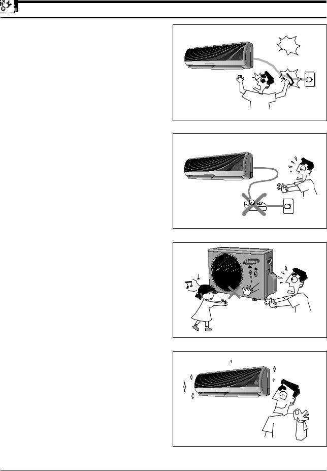
1.Warning: Prior to repair, disconnect the power cord from the circuit breaker.
2.Use proper parts: Use only exact replacement parts. (Also, we recommend replacing parts rather than repairing them.)
3.Use the proper tools: Use the proper tools and test equipment, and know how to use them. Using defective tools or test equipment may cause problems later-intermittent contact, for example.
4.Power Cord: Prior to repair, check the power cord and replace it if necessary.
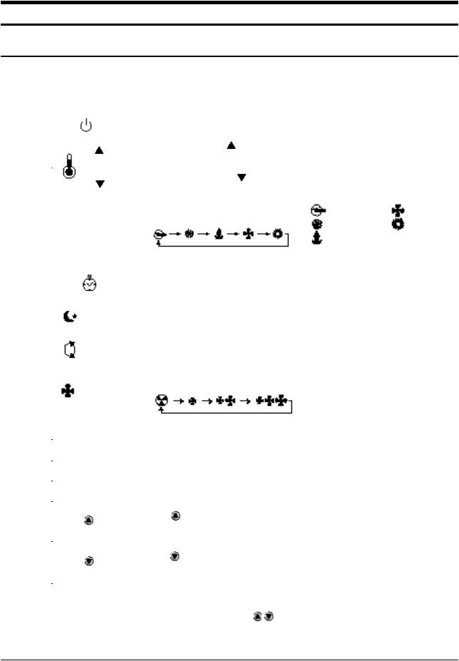
5.Avoid using an extension cord, and avoid tapping into a power cord. This practice may result in malfunction or fire.
6.After completing repairs and reassembly, check the insulation resistance. Procedure: Prior to applying power, measure the resistance between the power cord and the ground terminal. The resistance must be greater than 30 megohms.
7.Make sure that the grounds are adequate.
8.Make sure that the installation conditions are satisfactory. Relocate the unit if necessary.
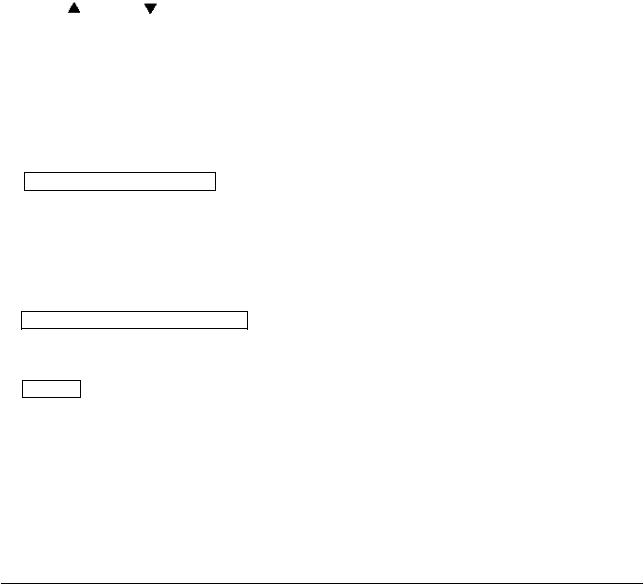
9.Keep children away from the unit while it is being repaired.
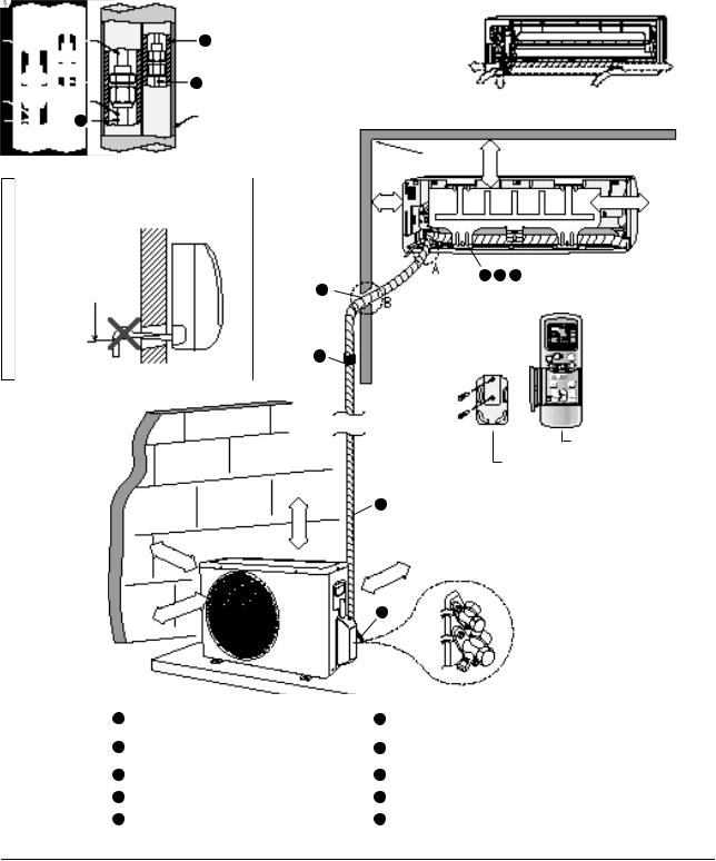
10.Be sure to clean the unit and its surrounding area.
Fig. 1-1 Avoid Dangerous Contact
Fig. 1-2 No Tapping and No Extension Cords
Fig. 1-3 No Kids Nearby!
Fig. 1-4 Clean the Unit
Samsung Electronics |
1-1 |

M E M O
1-2 |
Samsung Electronics |

2. Product Specifications
2-1 Table
|
|
|
|
|
Model (Indoor) |
|
|
|
AQV12F2VE |
Remark |
|||
Item |
|
|
|
|
|
|
(Outdoor) |
|
|
|
UQV12A0TE |
||
|
|
|
|
|
|
|
|
|
|
||||
Power Source |
|
|
|
|
ø-V-Hz |
|
|
1-220/240-50 |
|
|
|||
|
|
|
Capacity |
|
|
W |
|
|
3,500 (2,580~4,100) |
|
|
||
|
|
|
|
|
|
|
|
|
|
|
|
|
|
|
|
|
|
|
|
|
Btu/h |
|
|
12,000 (8,800~14,000) |
|
|
|
|
Cooling |
|
Energy efficiency ratio |
|
Btu/wh |
|
|
9.4 (11.3~8.4) |
|
|
|||
|
|
|
Air flow |
|
|
m2/min |
|
|
8.4 |
|
|
||
|
|
|
Moisture removal |
|
L/h |
|
|
1.9 |
|
|
|||
Performan |
|
|
Noise level |
Indoor |
|
dBA |
|
|
36~40 |
|
|
||
|
|
|
|
Outdoor |
|
|
|
51 |
|
|
|||
ce |
|
|
|
|
|
|
|
|
|
|
|||
|
|
Capacity |
|
|
W |
|
|
3,800 (2580~4830) |
|
|
|||
|
|
|
|
|
|
|
|
|
|||||
|
|
|
|
|
|
|
Btu/h |
|
|
13,000 (8800~16500) |
|
|
|
|
Heating |
|
Energy efficiency ratio |
|
Btu/wh |
|
|
9.8 (11.9~8.2) |
|
|
|||
|
|
|
Air flow |
|
|
m3/min |
|
|
8.8 |
|
|
||
|
|
|
Noise level |
Indoor |
|
dBA |
|
|
34~38 |
|
|
||
|
|
|
|
|
Outdoor |
|
|
|
52 |
|
|
||
|
|
|
|
|
|
|
|
|
|
|
|||
|
Available |
voltage range |
|
|
V |
|
|
187~264 |
|
|
|||
|
|
|
Running amperes |
|
A |
|
5.6 (3.7~7.1), (MAX 12A↓) |
|
|||||
|
Cooling |
|
Power input |
|
|
W |
|
|
1,280 (780~1,650) |
|
|
||
|
|
|
Power factor |
|
% |
|
|
95.0 (90.0~97.0) |
|
|
|||
Electrical |
|
|
Running amperes |
|
A |
|
5.7 (3.3~8.5), (MAX 12A↓) |
|
|||||
Heating |
|
Power input |
|
|
W |
|
|
1,330 (740~1,980) |
|
|
|||
Rating |
|
|
|
|
|
|
|
||||||
|
|
Power factor |
|
% |
|
|
98.0(94.0~97.0) |
|
|
||||
|
|
|
|
|
|
|
|
||||||
|
Starting |
current |
|
|
A |
|
|
|
12 ↓ |
|
|||
|
Fuse capacity |
|
|
|
|
A X V |
|
|
3.15X250 / 20X250 |
|
|||
|
Power cord |
|
|
|
|
A X V |
|
|
|
12 X 250 |
|
||
|
Cable-connector |
|
|
mm2 X C |
|
|
|
1.5 X 4 |
|
||||
Compre |
Type |
|
|
|
- |
|
|
|
Single Rotary |
|
|||
Model name |
|
|
|
- |
|
|
|
48V135RV1E4 |
|
||||
ssor |
|
|
|
|
|
|
|
||||||
Safety devices |
|
- |
|
|
|
204CT |
|
||||||
|
|
|
|
|
|
||||||||
|
Indoor |
|
Model name |
|
- |
|
|
AMPFS-040WTVB |
|
||||
Fan |
|
|
Running capacitor |
|
µF X VAC |
|
|
|
1.5 X 450 |
|
|||
motor |
Outdoor |
|
Model name |
|
- |
|
|
AMASS-020WTVB |
|
||||
|
|
|
Running capacitor |
|
µF X VAC |
|
|
|
1.5 X 450 |
|
|||
Refrigerant |
tube |
|
Narrow tube : Liquid |
|
mm X MT |
|
|
|
OD6.35 X 5 |
|
|||
|
|
|
Wide tube : Gas |
|
mm X MT |
|
|
|
OD12.7 X 5 |
|
|||
Capillary tube |
|
Cooling |
|
|
mm |
|
|
|
ID1.7 X 800 |
|
|||
|
|
|
Heating |
|
|
mm |
|
|
|
ID1.7 X 600 |
|
||
Refrigerant to charge |
(R22) |
|
|
gr |
|
|
1,000 |
|
|
||||
Dimension |
|
|
Indoor unit : W x H x D |
|
|
|
|
|
815x298x193 |
|
|||
|
|
|
Outdoor unit : W x H x D |
|
|
|
|
|
762x532x280 |
|
|||
Weight |
|
|
Indoor unit |
|
|
|
|
|
9.2 |
|
|
||
|
|
|
Outdoor unit |
|
|
|
|
|
44.0 |
|
|
||
Remark : Text condition |
|
|
|
|
|
|
|
|
|
|
|||
|
|
|
|
Indoor room |
|
|
Outdoor room |
|
|
||||
|
|
|
|
|
|
|
|
|
|
|
|||
|
|
|
|
Cooling test |
|
DB27˚C / WB19˚C |
|
DB35˚C / WB24˚C |
|
|
|||
|
|
|
|
|
|
|
|
|
|
|
|
||
|
|
|
|
Heating test |
|
DB20˚C / - |
|
|
DB 7˚C / WB 6˚C |
|
|
||
|
|
|
|
|
|
|
|
|
|
|
|
|
|
Samsung Electronics |
2-1 |

2-2 Dimensions
2-2-1 Indoor Unit
(Remote control)
(Front view)
Air
in
Air out
Installation plate
(Rear view)
2-2-1 Outdoor Unit
(Front view) |
(Rear view) |
2-2 |
Samsung Electronics |

2-3 Refrigerating Cycle Block Diagram
INDOOR UNIT |
|
|
|
|
|
|
|
|
|
|
|
|
|
|
OUTDOOR UNIT |
|||||||||||||||||
|
|
|
|
|
|
|
|
|
|
|
|
|
|
|
|
|
|
|
|
|
|
|
|
|
|
|
|
|
|
|
|
|
|
|
|
|
|
|
|
|
|
|
|
|
|
|
|
|
|
|
|
|
|
|
|
|
|
|
|
|
|
|
|
|
|
|
Capillary tube |
|
T |
2-way valve |
Check valve |
|
|
|
|
Liquid side |
|
|
|
Capillary tube |
Heat |
|
Heat |
exchanger |
|
exchanger |
(Evaporator) |
|
(Condenser) |
|
T |
|
|
Gas side |
|
|
3-way valve |
4-way valve |
|
|
|
|
|
Cooling |
|
|
Heating |
|
|
Compressor |
|
|
Gas leak check point |
|
|
|
|
|
|
|
|
|
|
|
|
|
|
|
|
|
|
|
|
|
|
|
|
|
|
|
|
|
|
|
|
|
|
|
|
|
|
|
|
|
|
|
|
Samsung Electronics |
2-3 |
||||||||||||||||||||||||||||||||||||||||||

M E M O
2-4 |
Samsung Electronics |
3. Operating Instructions and Installation
3-1 Operating Instructions
3-1-1 Name & Function of Key in remote controller
NO |
|
|
NAMED OF KEY |
|
|
FUNCTION OF KEY |
|
|
|||
|
|
|
|
|
|
|
|
||||
1 |
|
|
|
|
|
On/Off Button. Use this button to start and stop air conditioner. |
|
||||
|
|
|
|
|
|
|
|
|
|
||
2 |
|
|
|
|
(UP) |
Temp up button. If the |
button is pressed once, |
|
|
||
|
|
|
|
|
the setting temperature is increased by 1°C |
|
|
||||
|
|
|
|
|
|
|
|
||||
|
|
|
|
|
|
|
|
|
|||
|
|
|
|
|
(DOWN) |
Temp down button. If the |
button is pressed once, |
|
|||
|
|
|
|
|
the setting temperature is decreased by 1°C |
|
|
||||
|
|
|
|
|
|
|
|
||||
|
|
|
|
|
|
|
|
|
|
||
|
|
|
|
|
|
|
|
|
|
|
|
3 |
|
|
|
|
|
Each time you press this button, |
|
: Auto Mode |
: Fan Only Mode |
||
|
|
MODE |
MODE is changed in the following order. |
: Cool Mode |
: Heat Mode |
||||||
|
|
|
|
|
|
||||||
|
|
|
|
|
|
|
|
|
|
: Dry Mode |
|
|
|
|
|
|
|
|
|||||
4 |
|
TURBO |
Use this button to provide heavy duty cooling & Heating for 30 minutes. |
|
|||||||
|
|
|
|
|
|
|
|
||||
5 |
|
OFF |
|
|
|
Set up the reserve or cancel the timer on and timer off quickly |
|
||||
|
|
|
|
|
|
|
|
|
|
||
|
|
|
|
|
|
|
|
|
|
|
|
6 |
|
|
|
|
|
Use this button for sleep operation. |
|
|
|
||
|
|
|
|
|
|
|
|
||||
|
|
|
|
|
|
(The SLEEP mode can be selected at COOL and HEAT mode.) |
|
||||
|
|
|
|
|
|
|
|
|
|
|
|
7 |
|
|
|
|
|
Adjusts air flow vertically. |
|
|
|
|
|
|
|
|
|
|
|
|
|
|
|
||
|
|
|
|
|
|
|
|
|
|
||
8 |
|
|
|
|
|
Each time you press this button, |
|
|
|
||
|
|
|
|
|
|
FAN SPEED is changed in the following order. |
|
|
|||
|
|
|
|
|
|
|
|
|
|
||
9 |
C |
|
|
ON TIMER |
Set up the time that operation start. |
|
|
|
|||
|
O |
|
|
|
|
|
|
|
|
|
|
10 |
|
|
|
|
|
|
|
|
|
|
|
V |
|
|
OFF TIMER |
Set up the time that operation stop. |
|
|
|
||||
|
E |
|
|
|
|
|
|
|
|
|
|
|
|
|
|
|
|
|
|
|
|
|
|
11 |
R |
T |
|
SET |
Use this button to reserve the timer on. |
|
|
||||
|
|
|
|
|
|
|
|
|
|
|
|
12 |
|
|
CANCEL |
Use this button to reserve or cancel the timer on and timer off. |
|
||||||
|
I |
|
|
||||||||
|
|
M |
|
|
|
|
|
|
|
|
|
13 |
|
|
|
|
|
|
|
|
|
|
|
|
E |
|
|
(UP) |
If the |
button is pressed once, the time increase by one minute |
|
||||
|
|
R |
|
|
|
||||||
|
|
|
|
during the time set mode, and ten minutes during the timer set mode. |
|
||||||
|
|
|
|
|
|
|
|||||
|
|
|
|
|
|
|
|
|
|
|
|
14 |
|
|
|
|
(DOWN) |
If the |
button is pressed once, the time decrease by one minute |
|
|||
|
|
|
|
|
|
||||||
|
|
|
|
|
during the time set mode, and ten minutes during the timer set mode. |
|
|||||
|
|
|
|
|
|
|
|||||
|
|
|
|
|
|
|
|
|
|
|
|
15 |
|
|
|
|
|
Without regard to ON/OFF condition in remote controller, |
|
||||
|
|
|
|
|
|
|
|||||
|
|
|
|
TIME |
use this button to set current time. |
|
|
|
|||
|
|
|
|
Adjust the current time using |
button. |
|
|
||||
|
|
|
|
|
|
|
|
||||
|
|
|
|
|
|
(Data can be transmitted after setting up the time) |
|
|
|||
|
|
|
|
|
|
|
|
|
|
|
|
|
|
|
|
|
|
|
|
|
|
|
|
|
|
|
|
|
|
|
|
|
|
|
|
Samsung Electronics |
3-1 |
Operating Instructions and Installation
3-1-2 Name & Function of Key in remote controller
1.AUTO MODE : In this mode, operation mode(COOL, HEAT) is selected automatically by the room temperature of initial operation.
Room Temp |
Operation Type |
|
|
Tr³ 21°C+DT |
Cool Operation (Set Temp:24°C+DT) |
|
|
21°C +DT>Tr |
Heat Operation (Set Temp : 22°C+DT) |
|
|
DT= -2°, -1°C, 0°C+1°C+2°C
DT is controlled by setting temperature up( )/down( ) key of remote controller
2.COOL MODE : The unit operates according to the difference between the setting and room temperature. (18°C~30°C)
3.HEAT MODE : The unit operates according to the difference between the setting and room temperature.(16°C~30°C) *Prevention against cold wind : For about 3~5 minutes after initial operation, thermo control or “defrost”, the indoor fan will either not operate or operate very slowly, then switch to the selected fan speed. This period is to allow the indoor unit's heatexchanger to prewarm before emitting warm air.
*High temperature release function : The outdoor unit for and compressor ON/OFF control for safety operation, when the overheat is heat exchanger of indoor unit. *Defrost : Deicing operation is controlled by outdoor unit's heat exchanger temperature and outdoor temperature and accumulating time of compressor's operation. De-ice end by sensing of the processing time by de-ice Condition.
4.DRY MODE :
The unit operates in DRY mode. *Protective function : Low temperature release. (Prevention against freeze)
5.TURBO MODE : This mode is available in AUTO, COOL, HEAT, DRY, FAN, SLEEP Mode.
When this button is pressed at first, the air conditioner is operated “powerful” state for 30 minutes regardless of the set temperature, room temperature.
When this button is pressed again, or when the operating time is 30 minutes, turbo operation mode is canceled and returned to the previous mode.
*But, if you press the TURBO button in DRY or FAN mode that is changed with AUTO mode automatically.
6.SLEEP MODE : Sleep mode is available only in COOL or HEAT mode.
The operation will stop after 6 hours.
*In COOL mode : The setting temperature is automatically raised by 1°C each 1hour When the temperature has been raised by total of 2°C, that temperature is maintained.
*In HEAT mode : The setting temperature is automatically droped by 1°C each 1hour. When the temperature has been droped by total of 2°C, that temperature is maintained.
7.FAN SPEED : Manual / Auto
Fan speed automatically varies depending on both the difference between setting and the room temperature.
3-2 |
Samsung Electronics |
Operating Instructions and Installation
8.COMPULSORY OPERATION :
For operating the air conditioner without the remote controller.
*AUTO : The operating is the same function that AUTO MODE in the remote controller.
9.SWING : BLADE-H is rotated vertically by the stepping motor.
*Swing Set / Auto |
: Press the |
button |
|
under the remote control is |
on |
||
LCD the |
and the blades move up and |
||
down, |
43°. If the one more time press |
||
the button, blatles location is stop.
10.Quick OFF TIMER: OFF timer (quick timer) allows reservation or cancel the timer on and timer off quickly
When OFF timer button is pressed at operating state, LCD displays the polling state sequentially.
The LCD also displays the time remaining.
11.24-Hour ON/OFF Real Setting Timer. : The air conditioner is turned ON at a specified time using ON TIMER .
OFF TIMER : The air Conditioner is turned OFF at a specified time using OFF TIMER . *ON TIMER : Only timer LED lights on.
*OFF TIMER : Both timer and operation LED lights on.
12.BUZZER SOUND : Whenever the ON/OFF button is pressed or whenever change occurs to the condition which is set up or select, the compulsory operation mode, buzzer is sounded "beep"
13.SELF Diagnosis
The indoor unit observes operation of the air-conditioner, and displays the results of self diagnosis on display pannel.
|
|
|
|
|
|
Error mode |
Opera- |
Defrost |
Reserva- |
Power |
Fan |
Turbo |
|
tion |
tion |
monitor |
|
|||
|
|
|
|
|
|
|
X |
X |
X |
X |
X |
X |
Operation off |
|
|
|
|
|
|
|
|
X |
X |
X |
X |
X |
Power reset |
|
|
|
|
|
|
|
X |
X |
|
X |
X |
X |
Trouble of indoor temperature |
|
sensor (open/short) |
|||||
|
|
|
|
|
|
|
|
|
|
|
|
|
|
|
|
|
|
|
|
Temperature sensor trouble of |
|
X |
|
X |
X |
X |
the indoor heat exchanger |
|
|
|
|
|
|
(open/short) |
|
|
|
|
|
|
|
X |
X |
X |
X |
|
X |
Stuck of the indoor fan motor |
|
(trouble of rotation) |
|||||
|
|
|
|
|
|
|
|
|
|
|
|
|
|
|
|
|
|
|
|
Trouble of outdoor unit tempera- |
|
|
|
|
|
|
ture sensor |
|
|
|
|
|
|
- Discharge temperature sensor |
|
X |
X |
X |
|
X |
- OLP temperature sensor of |
|
|
|
|
|
|
COMP top |
|
|
|
|
|
|
- Defrost temperature sensor |
|
|
|
|
|
|
- Outdoor temperature sensor |
|
|
|
|
|
|
|
|
|
|
|
|
|
Communication trouble between |
X |
X |
|
X |
|
X |
the indoor and outdoor units |
|
|
(Misconnection or circuit trouble |
||||
|
|
|
|
|
|
|
|
|
|
|
|
|
of the indoor and outdoor units) |
|
|
|
|
|
|
|
X |
X |
X |
X |
X |
|
Abnormal increase of the opera- |
|
tion current |
|||||
|
|
|
|
|
|
|
|
|
|
|
|
|
|
X |
X |
|
X |
X |
|
Occurring of the inverter circuit |
|
|
instantaneous over current. |
||||
|
|
|
|
|
|
|
|
|
|
|
|
|
|
|
|
|
|
|
|
Abnormal increase of the COMP. |
X |
X |
X |
X |
|
|
Top and discharge gas tempera- |
|
|
|
|
|
|
ture. |
|
|
|
|
|
|
|
|
|
|
LAMP |
|
|
Refrigerant Refill operation (test |
|
|
|
ON |
|
|
operation) |
|
|
|
|
|
|
|
(Lamp status) |
|
|
|
|
|
|
: |
Lamp flickering |
X: Lamp off |
|
|
||
14.AUTO RESTART : The air conditioner starts immediately without control of remote controller when plugged.
It’s the case that the Auto-restart fanction works.
*Auto restart function is the convenient function where the operation state is memorized in the Memory IC during the blackout and the operation restarts when the power comes back.
Samsung Electronics |
3-3 |

3-2 Installation
3-2-1 Selecting Area for Installation
Select an area for installation that is suitable to the customer's needs.
3-2-1(a) Indoor Unit
1.Make sure that you install the indoor unit in an area providing good ventilation. It must not be blocked by an obstacle affecting the airflow near the air inlet and the air outlet.
2.Make sure that you install the indoor unit in an area allowing good air handling and endurance of vibration of the indoor unit.
3.Make sure that you install the indoor unit in an area where there is no source of heat or vapor nearby.
4.Make sure that you install the indoor unit in an area from which hot or cool air is spread evenly in a room.
5.Make sure that you install the indoor unit in an area away from TVs, audio units, cordless phones, fluorescent lighting fixtures and other electrical appliances (at least 1 meter).
6.Make sure that you install the indoor unit in an area which provides easy pipe connection with the outdoor unit, and easy drainage for condensed water.
7.Make sure that you install the indoor unit in an area which is large enough to accomodate the measurements shown in figure on the next page.
3-2-1(b) Outdoor Unit
1.Make sure that you install the outdoor unit in area not exposed to the rain or direct sun light.
(Install a separate sunblind if exposed to direct sun light.)
2.Make sure that you install the outdoor unit in area allowing good air moment, not amplifying noise or vibration, especially to avoid disturbing neighbours.
(Fix the unit firmly if it is mounted in a high place.)
3.Make sure that you install the outdoor unit in area providing good ventilation and which is not dusty. It must not be blocked by any obstacle affecting the airflow near the air inlet and the air outlet.
4.Make sure that you install the outdoor unit in area free from animals or plants.
5.Make sure that you install the outdoor unit in area not blocking the traffic.
6.Make sure that you install the outdoor unit in area easy to drain condensed water from the indoor unit.
7.Make sure that you install the outdoor unit in area which provides easy connection within the maximum allowable length of a coolant pipe(10 meters).
Note
1.Add 10 grams of refrigerant (R-22) for every 1 meter if the pipe length exceeds the standard pipe length of 5 meters.
2.Maintain a height between the indoor and outdoor units of less than 3 meters.
8.Make sure that you install the outdoor unit in an area which is large enough to accommodate the measurements
shown in figure on the next page.
3-2-1(c) Remote Control Unit
1.Make sure that you install the remote control unit in an area free from obstacles such as curtains etc, which may block signals from the remote control unit.
2.Make sure that you install the remote control unit in an area not exposed to
direct sunlight, and where there is no source of heat.
3.Make sure that you install the remote control unit in an area away from TVs, audio units, cordless phones, fluorescent lighting fixtures and other electrical appliances (at least 1 meter).
Caution :
It is harmful to the air conditioner if it is used in the following environments: greasy areas (including areas near machines), salty areas such as coast areas, areas where sulfuric gas is present such as hot spring areas. Contact your dealer for advice.
3-4 |
Samsung Electronics |
Operating Instructions and Installation
3-2-2 Installation diagram of indoor unit and outdoor unit
A Indoor unit gas leak test check point |
|
Piping may be laid to the rear, left, |
|||
|
|
|
right or down . |
|
|
Indoor unit |
3 |
|
|
|
|
|
|
|
Right |
|
Left |
|
2 |
|
Rear |
Down |
Rear |
Piping |
|
|
|||
|
|
|
|||
|
|
|
|
|
|
1 |
Tape vinyl |
|
|
|
|
|
|
|
|
|
|
|
|
|
|
|
|
B Drain hose installation
100mm or more
160mm or more
Cut the piping hole sloped slightly
7 8 9
5
6
Remote control
Remote control holder
4
10
1 |
|
Piping (Liquid) 1/4" |
6 |
Clamper tube |
|
|
|
|
|
|
|
2 |
9K BTU |
|
Piping(Gas)3/8” |
7 |
Installation plate |
12K BTU |
|
Piping(Gas)1/2” |
|||
|
|
|
|
||
|
|
|
|
|
|
3 |
|
Installation tube |
8 |
Pipe-connection |
|
|
|
|
|
|
|
4 |
|
Vinyl tape |
9 |
Screw |
|
|
|
|
|
|
|
5 |
|
Putty |
10 |
Drain hose |
|
|
|
|
|
|
|
Samsung Electronics |
3-5 |
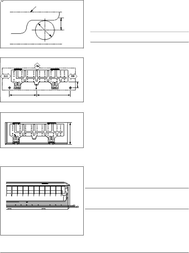
Operating Instructions and Installation
3-2-2(a) Fixing the Installation Plate
Installation plate
Pipe hole (ø65mm)
(Unit : mm)
280 |
340 |
(Unit : mm)
3-2-2(b) Purging the Unit
1.Determine the position of the pipe and drain hose hole using the right figure and drill the hole with an inner diameter of 65mm so that it slants slightly downwards.
2.If you are fixing the indoor unit to a… Then follow Steps…
Wall |
3. |
Window frame |
4 to 6. |
3.Fix the installation plate to the wall in a manner appropriate to the weight of the indoor unit.
If you are mounting the plate on a concrete wall with anchor bolts, the anchor bolts must not project by more than 20mm.
4.Determine the positions of the wooden uprights to be attached to the window frame.
5.Attach the wooden uprights to the window frame in a manner appropriate to the weight of the indoor unit.
6.Using tapped screws, attach the installation plate to the wooden uprights, as illustrated in the last figure opposite.
On delivery, the indoor unit is loaded with an inert gas. All this gas must therefore be purged before connecting the assembly piping. To purge the inert gas, proceed as fol - lows.
Unscrew the caps at the end of each pipe.
Result : All inert gas escapes from the indoor unit.
•To prevent dirt or foreign objects from getting into the pipes during installation, do NOT remove the caps completely until you are ready to connect the piping.
3-6 |
Samsung Electronics |
Operating Instructions and Installation
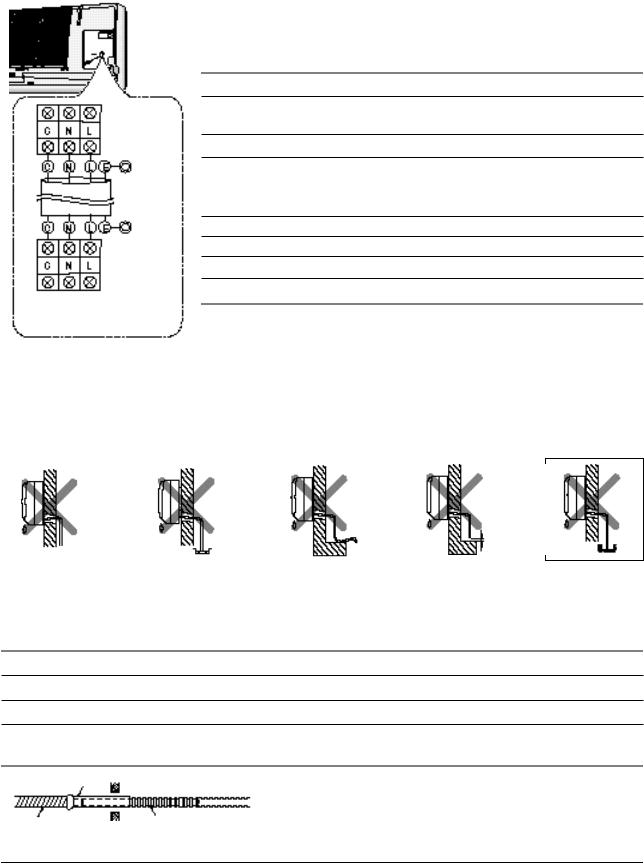
3-2-2(c) Connecting the Assembly Cable.
Indoor unit
Earth terminal
Earth terminal
Outdoor unit
L : Brown
N : Sky blue
C : Black
E : Yellow/ Green
The outdoor unit is powered from the indoor unit via the assembly cable. If the outdoor unit is more than five metres away from the indoor unit, the cable must first be extended to a maximum of ten metres.
1.Extend the assembly cable if necessary.
2.Open the front grille by pulling on the tabs on the lower right and left sides of the indoor unit.
3.Remove the screw securing the connector cover.
4.Pass the assembly cable through the rear of the indoor unit and connect the assembly cable to terminals C, N, L, E.
• Each wire is labelled with the corresponding terminal number.
5.Firmly fix the ass’y cable with clamp wire holder.
6.Pass the other end of the cable through the 65mm hole in the wall.
7.Replace the connector cover, carefully tightening the screw.
8.Close the front grille.
3-2-2(d) Installing and Connecting the Indoor Unit Drain Hose
Care must be taken when installing the drain hose for the indoor unit to ensure that any condensa - tion water is correctly drained outside.l When passing the drain hose through the 65mm hole drilled in the wall, check that none of the following situations occur.
|
|
|
|
|
|
|
The hose must |
The end of the drain |
|
Do NOT bend the |
|
Keep a clearance of at |
|
NOT slope upw |
hose must NOT be |
|
hose in different |
|
least 5cm between the |
|
ards. |
placed in water. |
|
directions. |
|
end of the hose and the |
|
|
|
|
|
|
|
ground. |
Do NOT place the end of the drain hose in a hollow.
To install the drain hose, proceed as follows.
1.If necessary, connect the 2-metre extension to the drain hose.
2.If you are using the extension, insulate the inside part of the extension drain hose with a shield.
3.Pass the drain hose under the refrigerant piping, taking care to keep the drain hose tight.
4.Pass the drain hose through the hole in the wall, making sure that it is sloping downwards, as shown in the illustrations above.
Shield
Drain hose |
Extension drain hose |
Samsung Electronics |
3-7 |

Operating Instructions and
3-2-2(e) Outdoor unit installation
Wiring connection
1.Remove the Handle-Cabi RH.
2.Firmly connect the cable connector in the terminal block.
3.Fasten the terminal to the hole marked
4.Firmly fix the ass'y cable with clamp wire holder.
5.Assemble the Handle-Cabi RH.
Installing and Connecting the Outdoor Unit Drain Hose
Drain hole
When using the air conditioner in the heating mode, ice may accumu - late. During de-icing, the condensed water must be drained off safely. Consequently, you must install a drain hose on the outdoor unit, fol - lowing the instructions below.
1Insert the drain plug into the drain hole on the underside of the outdoor unit.
2Connect the drain hose to the drain plug.
3Ensure that the drained water runs off correctly and safely.
3-8 |
Samsung Electronics |
Operating Instructions and Installation
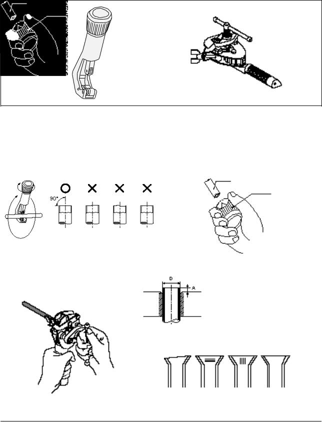
3-2-2(f) Flare Modification
• Tools used
Flare modification procedure
1) Cut the pipe using a pipe cutter. |
|
2) Remove burrs at the tip of the pipe cut. |
|
|
Caution : Burrs not removed may result in |
|
|
leakage of gas. |
|
|
Pipe |
Oblique Raughness |
Burr |
Reamer |
|
3) Insert a flare nut into the pipe and |
|
|
|
|
|
|
|
modifty flare. |
D |
|
|
|
|
|
|
Outer diameter |
A(mm) |
||||||
|
|
|
|
||||
|
|
|
A |
|
|||
|
|
|
|
|
|
||
|
|
|
|
|
ø6.35mm |
1.3 |
|
|
|
|
|
|
|||
|
|
|
|
|
|
|
|
|
|
|
|
|
ø9.52mm |
1.8 |
|
|
|
|
|
|
|
|
|
|
|
|
|
|
ø12.7mm |
2.0 |
|
|
|
|
|
|
|
|
* Unproper flaring
Inclined |
|
Surface |
|
Cracked |
Uneven |
|
|
damaged |
|
|
thickness |
|
|
|
|||
|
|
|
|
|
|
Samsung Electronics |
3-9 |
Operating Instructions and Installation
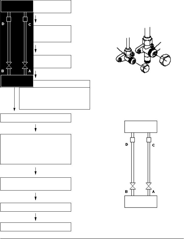
3-2-2(g) Air-Purge Procedure
•Use the refrigerant of the outdoor unit to purge air inside indoor unit and pipe.
1.Remove the caps from the 2-way valve(B) and the 3-way valve(A).
2.Turn the 2-way valve cock approx. 45° counterclockwise to open it. Close it about 10 seconds later.
Valve stem
Valve stem
Stopper
3.Check refrigerant leakage of each joint parts (A, B, C & D in right figure)
Leaking
not
leaking If leaking, tighten the flare nut one more time. If continues to leak, although the pipe fixing area has been tightened again,
repair the leaking area.
4.Open the 2-way valve again.
5.Open the service valve cap of the 3-way valve and press the needle valve to discharge gas for 3 seconds and leave it for about 1 minute.
Repeat the above procedure for 3 times to purge air.
Indoor Unit
Liquid pipe side |
Gas pipe side |
6.Open the 2-way valve and 3-way valve completely
2-way valve |
3-way valve |
Outdoor Unit
7.Close the cap of each valve.
8.Check each valve for leakage.
3-10 |
Samsung Electronics |
 Loading...