


Samsung AQ12A5MB, AQ12A5ME, AQ09A5ME, SH09ZA5, AQ07A5ME Service Manual
...ROOM AIR CONDITIONER
INDOOR UNIT |
OUTDOOR UNIT |
AQ12A5(6)MB |
UQ12A5(6)MB |
AQ12A5(6)ME |
UQ12A5(6)ME |
AQ09A5(6)ME |
UQ09A5(6)ME |
SH09ZA5(6) |
SH09ZA5(6)X |
AQ07A5(6)ME |
UQ07A5(6)ME |
SH07ZA5(6) |
SH07ZA5(6)X |
AQ09A7(8)ME |
UQ09A7(8)ME |
SH09ZA7(8) |
SH09ZA7(8)X |
AQ07A7(8)ME |
UQ07A7(8)ME |
SH07ZA7(8) |
SH07ZA7(8)X |
SERVICE Manual
AIR CONDITIONER |
CONTENTS |
1. Precautions
2. Product Specifications
3. Operating Instructions and
Installation
4. Disassembly and Reassembly
5. Troubleshooting
6. Exploded Views and Parts List
7. Block Diagrams
8. PCB Diagrams
9. Wiring Diagrams
10. Schematic Diagrams

ELECTRONICS
©Samsung Electronics Co., Ltd. Sep. 2000. Printed in Korea.
Code No. DB81-00181A(2)
1. Precautions
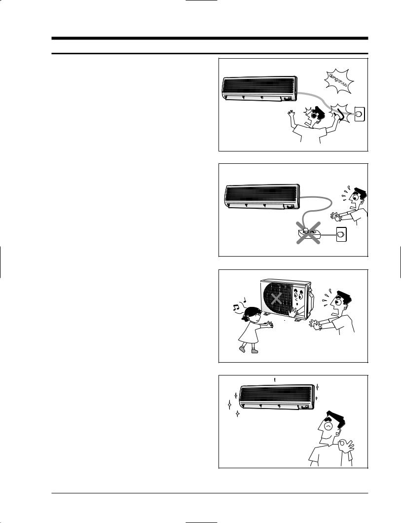
1.Warning: Prior to repair, disconnect the power cord from the circuit breaker.
2.Use proper parts: Use only exact replacement parts. (Also, we recommend replacing parts rather than repairing them.)
3.Use the proper tools: Use the proper tools and test equipment, and know how to use them. Using defective tools or test equipment may cause problems later-intermittent contact, for example.
4.Power Cord: Prior to repair, check the power cord and replace it if necessary.
5.Avoid using an extension cord, and avoid tapping into a power cord. This practice may result in malfunction or fire.
6.After completing repairs and reassembly, check the insulation resistance. Procedure: Prior to applying power, measure the resistance between the power cord and the ground terminal. The resistance must be greater than 30 megohms.
7.Make sure that the grounds are adequate.
8.Make sure that the installation conditions are satisfactory. Relocate the unit if necessary.
9.Keep children away from the unit while it is being repaired.
10.Be sure to clean the unit and its surrounding area.
Fig. 1-1 Avoid Dangerous Contact
Fig. 1-2 No Tapping and No Extension Cords
Fig. 1-3 No Kids Nearby!
.K |
O |
Fig. 1-4 Clean the Unit
Samsung Electronics |
1-1 |

MEMO
1-2 |
Samsung Electronics |

2. Product Specifications
2-1 Table
|
|
|
|
|
|
Model |
|
AQ12A5(6)MB |
AQ12A5(6)ME |
AQ09A5(6)ME/SH09ZA5(6)AS07A3(4)ME/SC07ZA3(4) |
AS12A1(2)ME/SC12ZA1(2)/SC12ZA1(2)AAQ07A5(6)ME/SH07ZA5(6) |
AQ09A7(8)ME/SH09ZA7(8) |
AQ07A7(8)ME/SH07ZA7(8) |
||||||||||||||
Item |
|
|
|
|
|
|
|
|
|
|
|
|
|
|
|
|
|
|
|
|
|
|
|
|
|||
|
|
|
|
|
|
Indoor unit |
|
Outdoor unit |
Indoor unit |
|
Outdoor unit |
IndoorIndoorunitunit |
|
OutdoorOutdoorunitunit |
IndoorIndoorunitunit |
|
OutdoorOutdoorunitunit |
Indoor unit |
|
Outdoor unit |
Indoor unit |
|
Outdoor unit |
||||
Type |
|
|
|
|
- |
|
|
Wall-mounting |
Wall-mounting |
Wall-mounting |
|
WallWall-mounting-mounting |
Wall-mounting |
Wall-mounting |
|||||||||||||
|
|
|
|
|
|
|
|
|
|
|
|
|
|
|
|
|
|
|
|
|
|
||||||
|
|
Cooling |
|
|
BTU/h(KW) |
|
12000 |
|
12000 (3.4) |
90007500(2.72) |
|
750012000(2.3) |
9000 (2.64) |
7500 (2.2) |
|||||||||||||
|
|
|
|
|
|
|
|
|
|
|
|
|
|
|
|
|
|
|
|
|
|
||||||
|
|
Heating |
|
|
BTU/h(KW) |
|
13000 |
|
13000 (3.7) |
10000- (2.95) |
|
8000 (2- .38) |
10000 (2.93) |
8000 (2.34) |
|||||||||||||
|
|
|
|
|
|
|
|
|
|
|
|
|
|
|
|
|
|
|
|
|
|
|
|
|
|
|
|
|
|
Dehumiditying |
|
|
I/h |
|
|
1.9 |
|
|
1.9 |
|
1.94 |
|
|
01.9.4 |
|
1.4 |
|
0.9 |
|||||||
|
|
Air volume |
|
Cooling |
m3/min |
7.4 |
|
|
19 |
7.4 |
|
19 |
6.50.3 |
|
20.185 |
75..46 |
|
1918 |
6.0 |
|
20.5 |
5.6 |
|
20.5 |
|||
|
|
|
|
|
|
|
|
|
|
|
|
|
|
|
|
|
|
|
|
|
|
|
|
||||
Perfor- |
|
Heating |
8.1 |
|
|
19 |
8.1 |
|
19 |
6.7- |
|
|
- 18 |
5-.5 |
|
- 18 |
6.7 |
|
20.5 |
5.5 |
|
20.5 |
|||||
|
|
|
|
|
|
|
|
|
|
|
|
|
|||||||||||||||
mance |
Noise |
|
Cooling |
dB |
|
41 |
|
|
53 |
41 |
|
53 |
3833 |
|
4751 |
3835 |
|
5050 |
38 |
|
51 |
35 |
|
50 |
|||
|
|
|
|
|
|
|
|
|
|
|
|
|
|
|
|
|
|
|
|
|
|
|
|
|
|||
|
|
|
Heating |
|
41 |
|
|
53 |
41 |
|
53 |
38- |
|
|
- 51 |
35- |
|
- 50 |
38 |
|
51 |
35 |
|
50 |
|||
|
|
|
|
|
|
|
|
|
|
|
|
|
|
|
|||||||||||||
|
|
Energy efficiency ratio |
Cooling |
BTU/h |
W |
|
9.375 |
|
|
10.0 |
910.375.0 |
|
|
1010.0.3 |
|
9.47 |
|
10.0 |
|||||||||
|
|
Heating |
|
10.0 |
|
|
10.6 |
10.-752 |
|
|
10.959- |
|
10.75 |
|
10.96 |
||||||||||||
|
|
|
|
|
|
|
|
|
|
|
|
|
|
||||||||||||||
|
|
|
|
|
|
|
|
|
|
|
|
|
|
|
|
|
|
|
|
|
|
|
|||||
|
|
Power |
|
|
V-Hz |
|
|
1-220 -60 |
|
1-220 / 240-50 |
1-220 / 240-50 |
|
11-220- 20//240240-50-50 |
1-220 / 240-50 |
1-220 / 240-50 |
||||||||||||
|
|
|
|
|
|
|
|
|
|
|
|
|
|
|
|
|
|
|
|
|
|
|
|
|
|
|
|
|
|
Power Consumption |
Cooling |
W |
|
|
1280 |
|
|
1200 |
|
750960 |
|
|
7501170 |
|
950 |
|
750 |
||||||||
|
|
|
|
|
|
|
|
|
|
|
|
|
|
|
|
|
|
|
|
|
|
|
|
||||
|
|
Heating |
|
|
1300 |
|
|
1230 |
|
930- |
|
|
|
730- |
|
930 |
|
730 |
|||||||||
|
|
|
|
|
|
|
|
|
|
|
|
|
|
|
|
||||||||||||
|
|
Operating Current |
Cooling |
A |
|
|
6.0 |
|
|
5.4 |
|
34.34 |
|
|
35.3.0 |
|
4.2 |
|
3.3 |
||||||||
|
|
|
|
|
|
|
|
|
|
|
|
|
|
|
|
|
|
|
|
|
|
|
|
||||
|
|
Heating |
|
|
6.2 |
|
|
5.5 |
|
4-.2 |
|
|
3.3- |
|
3.9 |
|
3.2 |
||||||||||
|
|
|
|
|
|
|
|
|
|
|
|
|
|
|
|||||||||||||
Power |
Power factor |
|
Cooling |
% |
|
|
97 |
|
|
96.6 |
|
948.89 |
|
|
10198..78 |
|
98.3 |
|
98.8 |
||||||||
|
|
|
|
|
|
|
|
|
|
|
|
|
|
|
|
|
|
|
|
|
|
|
|||||
|
Heating |
|
|
95.3 |
|
|
97.2 |
|
96-.3 |
|
|
96.-7 |
|
10.37 |
|
99.2 |
|||||||||||
|
|
|
|
|
|
|
|
|
|
|
|
|
|
|
|||||||||||||
|
|
Starting current |
|
|
A |
|
|
30 |
|
|
30 |
|
30 |
|
|
3030 |
|
30 |
|
30 |
|||||||
|
|
|
|
|
|
|
|
|
|
|
|
|
|
|
|
|
|
|
|
|
|
|
|
|
|
|
|
|
|
Power cord |
|
Length |
m |
|
|
- |
|
|
|
- |
|
- |
|
|
|
-- |
|
- |
|
- |
|||||
|
|
|
|
|
|
|
|
|
|
|
|
|
|
|
|
|
|
|
|
|
|
|
|
|
|
||
|
|
|
Number of core wire |
|
|
- |
|
|
|
- |
|
- |
|
|
|
-- |
|
- |
|
- |
|||||||
|
|
|
|
|
|
|
|
|
|
|
|
|
|
|
|
||||||||||||
|
|
Fuse capacity |
|
|
A |
|
|
250V-10 / 16A |
250V-10 / 16A |
250V-10 / 16A |
|
250V250V-10-10//16A16A |
250V-10 / 16A |
250V-10 / 16A |
|||||||||||||
|
|
|
|
|
|
|
|
|
|
|
|
|
|
|
|
|
|
|
|
|
|
|
|
|
|
||
|
|
Outer |
|
Width x Height |
mm |
|
790 x 245 x 165 |
|
762 x 532 x 280 |
790 x 245 x 165 |
|
762 x 532 x 280 |
790790x x245245x x165165 |
|
660660x 470x 497x 242x 235 |
790790xx245245xx165165 |
|
720660x 532x 497x 245x 235 |
790 x 245 x 165 |
|
660 x 470 x 242 |
790 x 245 x 165 |
|
660 x 470 x 242 |
|||
|
|
Dimension |
|
x Depth |
|
|
|
|
|
|
|
|
|
|
|
|
|
|
|
|
|
|
|
|
|||
|
|
|
inch |
|
31.1 x 9.6 x 6.5 |
|
30 x 20.9 x 11 |
31.1 x 9.6 x 6.5 |
|
30 x 20.9 x 11 |
3131.1.1x x9.96.6x x6.65.5 |
|
6.260 xx1819.5.6xx99.3 |
3131..11xx99..66xx66..55 |
|
28.263 xx2119.0.6xx99.6.3 |
31.1 x 9.6 x 6.5 |
|
26 x 18.5 x 9.5 |
31.1 x 9.6 x 6.5 |
|
26 x 18.5 x 9.5 |
|||||
|
|
Weight |
|
|
|
|
7.7 |
|
|
35 |
7.7 |
|
35 |
7.7.7 |
|
2529 |
77..77 |
|
38.290 |
7.7 |
|
2.5 |
7.7 |
|
25 |
||
|
|
|
|
|
|
|
|
|
|
|
|
|
|
|
|
|
|
|
|
|
|
|
|
||||
|
|
Refrigerant pipe |
Liquid |
mm x L(MT) |
|
ø6.35 x 5 |
|
ø6.35 x 5 |
ø6.35 x 5 |
|
ø6ø6.35.35xx55 |
|
ø6.35 x 5 |
|
ø6.35 x 5 |
||||||||||||
|
|
GAS |
mm x L(MT) |
|
ø12.7 x 5 |
|
ø12.7 x 5 |
ø9.52 x 5 |
|
ø9ø12.52.7xx55 |
|
ø9.52 x 5 |
|
ø9.52 x 5 |
|||||||||||||
|
|
|
|
|
|
|
|
|
|
||||||||||||||||||
|
|
|
|
|
|
|
|
|
|
|
|
|
|
|
|
|
|
|
|
|
|
||||||
Size |
Drain hose |
|
|
D x L(mm) |
|
ø18 x 2000 |
|
ø18 x 2000 |
ø18 x 2000 |
|
ø18ø18xx20002 0 |
ø18 x 2000 |
ø18 x 2000 |
||||||||||||||
Compressor |
|
Type |
|
|
|
|
Rotary |
|
|
Rotary |
Rotary |
|
|
RotaryOTARY |
|
Rotary |
|
Rotary |
|||||||||
|
|
|
|
|
|
|
|
|
|
|
|
|
|||||||||||||||
|
|
|
|
|
|
|
|
|
|
|
|
|
|
|
|
|
|
|
|
|
|
|
|
|
|
|
|
|
|
|
|
Motor |
Type |
|
|
- |
|
|
- |
- |
|
- |
-- |
|
- |
- |
-- |
|
- - |
- |
|
- |
- |
|
- |
|
|
|
|
|
|
|
|
|
|
|
|
|
|
|
|
|
|
|
|
|
|
|
|
|
|
|
|
|
|
|
|
|
Rated output |
|
|
- |
|
|
- |
- |
|
- |
-- |
|
- |
- |
-- |
|
1215- |
- |
|
- |
- |
|
- |
|
|
Blower |
|
Type |
|
|
|
Cross-flow |
|
Propeller |
Cross-flow |
|
Propeller |
CrossCross-flow-flow |
|
PropellPropellerr |
CrossCross--flowflow |
|
PropellerPropeller |
Cross-flow |
|
Propeller |
Cross-flow |
|
Propeller |
||
|
|
|
|
|
|
|
|
|
|
|
|
|
|
|
|
|
|
|
|
|
|
|
|
|
|
||
|
|
|
|
Motor |
Type |
|
|
Resin |
|
steel |
Resin |
|
steel |
ResinResin |
|
steelsteel |
ResinResin |
|
steelsteel |
Resin |
|
steel |
Resin |
|
steel |
||
|
|
|
|
|
Rated output |
W |
|
15 |
|
|
25 |
15 |
|
25 |
1515 |
|
2525 |
1515 |
|
2525 |
15 |
|
25 |
15 |
|
25 |
|
Heat exchanger |
|
|
|
|
2ROW 12STEP |
|
1ROW 20STEP |
2ROW 12STEP |
|
1ROW 20STEP |
2ROW2ROW12STEP12STEP |
|
1ROW1ROW20STEP18STEP |
2ROW2ROW12STEP12STEP |
|
2ROW1ROW20STEP18STEP |
2ROW 12STEP |
|
1ROW 18STEP |
2ROW 12STEP |
|
1ROW 18STEP |
|||||
Refrigerant control unit |
|
|
|
|
|
CAPILLARY TUBE |
CAPILLARY TUBE |
CAPILLARY TUBE |
|
CAPILLARYCAPI LARYTUBETUBE |
CAPILLARY TUBE |
CAPILLARY TUBE |
|||||||||||||||
Freezer oil capacity |
|
|
|
|
|
410 |
|
|
410 |
|
360 |
|
|
360410 |
|
360 |
|
360 |
|||||||||
Refrigerant to change(R-22) |
|
|
|
|
800 |
|
|
820 |
|
67000 |
|
|
6301070 |
|
670 |
|
630 |
||||||||||
Protection device |
|
|
|
|
MRA 12002-9200/MRA 12002-12008 |
MRA 12030-12008 |
MRAC1208612054-12008-9622 |
|
MRARAC 1208630-120089622 |
MRA 12110-12008 |
MRA 12086-12008 |
||||||||||||||||
|
|
|
|
|
|
|
|
|
|
|
|
|
|
|
|
|
|
|
|
|
|
|
|
|
|||
Cooling test Condition |
|
|
|
|
|
|
|
|
INDOOR UNIT : DB27°C WB19°C |
|
|
|
|
|
|
|
OUTDOOR UNIT : DB35°C WB24°C |
|
|
|
|||||||
|
|
|
|
|
|
|
|
|
|
|
|
|
|
|
|
|
|
|
|
|
|
|
|
||||
Maximum operation Condition |
|
|
|
|
|
|
|
INDOOR UNIT : DB32°C WB23°C |
|
|
|
|
|
|
|
OUTDOOR UNIT : DB43°C WB26°C |
|
|
|
||||||||
|
|
|
|
|
|
|
|
|
|
|
|
|
|
|
|
|
|
|
|
|
|
|
|
|
|
|
|
Samsung Electronics |
2-1 |

3. Operating Instructions and Installation
3-1 Operating Instructions
3-1-1 Name & Function of Key in remote controller
NO |
NAMED OF KEY |
|
FUNCTION OF KEY |
|
|
1 |
|
Power On/Off button to start and stop airconditioner or timer set up |
|
||
|
|
|
|
|
|
|
(UP) |
Temp. up button. To increase the temperatute by the pressing |
|
||
2 |
|
the temperature button |
|
|
|
|
|
|
|
|
|
|
(DOWN) |
Temp. down button. To decrease the temperature by the pressing |
|
||
|
|
the temperature button |
|
|
|
|
|
Each time you press this button |
: Auto Mode |
: Fan Only |
|
|
|
Mode is changed in the following order |
: Heat Mode |
||
3 |
|
|
|
: Cool Mode |
|
|
|
|
|
|
|
|
|
|
|
: Dry Mode |
|
|
|
Press |
until the appearance. the air condition cools or heats |
|
|
|
|
the room as quickly as possible. after 30minutes, the air, |
|
||
|
|
the airconditioner is reset automatically to the previous mode |
|
||
4 |
|
Press |
until the appearance. the sleep timer can be used when |
|
|
|
|
|
|||
|
|
you are cooling or heating your room to switch the air conditioner off |
|
||
|
|
automatically after a perriod of six hours. |
|
||
|
|
Each time you press this button, |
|
|
|
5 |
|
FAN SPEED is changed in the following order. |
|
||
|
|
|
|
|
|
6 |
|
Adjust air flow vertically. |
|
|
|
7 |
|
The ON Timer enables you to switch on the air conditioner automatically |
|||
|
after a given period of time that is from 30 minutes to 24 hours. |
|
|||
|
|
To cancel the On Time, press the |
(Set/Cancel) button. |
|
|
|
|
The Off Timer enables you to switch off the air conditioner automatically |
|||
8 |
|
after a given period of time that is from 30 minutes to 24 hours. |
|
||
|
To cancel the On Time, press the |
(Set/Cancel) button. |
|
||
|
|
|
|||
|
|
To select the 5 way function with the remote control, press the 5 way |
|
||
|
|
button one or more times until the desired mode is selected.. |
|
||
|
|
Each time you press the 5 way button |
|
||
9 |
|
|
|
|
|
Each 5 way indicator on the indoor unit comes on in order.
Samsung Electronics |
3-1 |
Operating Instructions and Installation
3-1-1 Name & Function of Key in remote controller
1.AUTO MODE : In this mode, operation mode(COOL, HEAT) is selected automatically by the room temperature of initial operation.
Room Temp |
Operation Type |
Tr≥ 21°C+ T Cool Operation (Set Temp:AUTO SETTING)
21°C + T>Tr |
Heat Operation (Set Temp : 22°C+ T) |
ÆT= -1°C, -2°C, 0°C+1°C+2°C
ÆT is controlled by setting temperature up/down key of remote controller
2.COOL MODE : The unit operates according to the difference between the setting and room temperature. (18°C~30°C)
3.HEAT MODE : The unit operates according to the difference between the setting and room temperature.(16°C~30°C) *Prevention against cold wind : For about 3~5 minutes after initial operation, thermo control or “de-ice”, the indoor fan will either not operate or operate very slowly, then switch to the selected fan speed. This period is to allow the indoor unit's heatexchanger to prewarm before emitting warm air.
*High temperature release function : The outdoor unit for and compressor ON/OFF control for safety operation, when the overheat is heat exchanger of indoor unit. *De-ice : Deicing operation is controlled by indoor unit's heat exchanger temperature and accumulating time of compressor's operation.
De-ice end by sensing of the processing time by de-ice Condition.
4.DRY MODE : Has 3 states, each determined by room temperature.
The unit operates in DRY mode. *Compressor ON/OFF Time is controlled compulsorily(can not set up the fan speed, always breeze).
*Protective function : Low temperature release. (Prevention against freeze)
5.TURBO MODE : This mode is available in AUTO, COOL, HEAT, DRY, FAN MODE. When this button is pressed at first, the air conditioner is operated “powerful” state for 30 minutes regardless of the set temperature, room temperature.
When this button is pressed again, or when the operating time is 30 minutes, turbo operation mode is canceled and returned to the previous mode.
*But, if you press the TURBO button in DRY or FAN mode that is changed with AUTO mode automatically.
6.SLEEP MODE : Sleep mode is available only in COOL or HEAT mode.
The operation will stop after 6 hours.
*In COOL mode : The setting temperature is automatically raised by 1°C each 1hour When the temperature has been raised by total of 2°C, that temperature is maintained.
*In HEAT mode : The setting temperature is automatically droped by 1°C each 1hour. When the temperature has been droped by total of 2°C, that temperature is maintained.
7.FAN SPEED : Manual (3 step), Auto (4 step) Fan speed automatically varies depending on both the difference between setting and the room temperature.
3-2 |
Samsung Electronics |

8.COMPULSORY OPERATION :
For operating the air conditioner without the remote controller.
*AUTO : The operating is the same function that AUTO MODE in the remote controller. And each time you press the button the 5WAY func-tion is changed as follow.
STD NATURE POWER SAVING SILENCE POWER OFF
Each time you press This button, 5WAY function is changed in the following order STD(standard) NATURE POWER(High-speed) Saving(PowerSaving) Quite
STD(standard)( 


 ) : General operation
Mode
NATURE(  ) : The unit is operated according to health pattern control
POWER(  ) : The unit is operated in powerful state
SAVING(  ) : The unit is operated in power saving state
SILENCE(  ) : The unit is operated quitely
Each mode has Auto, Cool and SLEEP operation designed in advance.
9.SWING : BLADE-H is rotated vertically by the stepping motor.
*Memory louver : When ON/OFF button is pressed at stop state, the BLADE-H returns to its original location which is operating state before stop
*Swing Set : Press the  button under the remote control is displayed on LCD the
  and the blades move up and down. If the one
more time press the  button, blades location is stop.
10.24-Hour ON/OFF Real Setting Timer. : The air conditioner is turned ON at a specified time using  .
.
Operating Instructions and Installation
OFF TIMER : The air Conditioner is turned OFF at a specified time using  .
.
*ON TIMER : Only timer LED lights on. *OFF TIMER : Both timer and operation LED lights on.
11. SELF Diagnosis
LED DISPLAY
Check Point |
TIMER |
STD NATURE POWER SAVING SILENCE |
|
|
Indoor unit room temperature sensor error(open or short)
Indoor unit heat exchanger temperature sensor error(open or short)
Indoor fan mal function
EEPROM error
Option error(option wasn’t set up or option data error)
: LED |
: LED off |
blinking |
|
12.BUZZER SOUND : Whenever the ON/OFF button is pressed or whenever change occurs to the condition which is set up or select, the compulsory operation mode, buzzer is sounded "beep"
Samsung Electronics |
3-3 |

MEMO
3-4 |
Samsung Electronics |
4. Disassembly and Reassembly
Stop operation of the air conditioner and remove the power cord before repairing the unit.
4-1 Indoor Unit
No |
Parts |
|
Procedure |
Remark |
|
|
|
|
|
|
|
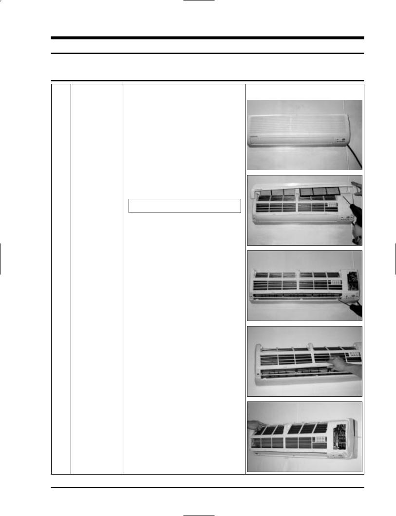
1 |
Front Grille |
1) |
Stop the air conditioner operation and block |
|
|
|
|
||||
|
|
|
the main power. |
|
|
|
|
2) |
Separate tape of front panel upper. |
|
|
|
|
|
|
|
|
3)Contract the second finger to the left, and right handle and pull to open the inlet grille.
4)Take the left and right filter out.
*Taking off the deodorizing filter.
5)Loosen one of the right fixing screw and separate the terminal cover.
6)Loosen three fixing screws of front grille.
7)Pull the upper left and right of discharge softly for the outside cover to be pulled out.
8)Pull softly the lower part of discharge and push it up.
Caution;
Assemble the front panel and fix the hooks of left and right.
Samsung Electronics |
4-1 |
Disassembly and Reassembly
No |
Parts |
|
Procedure |
Remark |
|
|
|
|
|
|
|
2 |
Ass’y Tray Drain. |
1) Do “1”above |
|
|
|
|
|
||||
|
|
2) |
Take all the connector of PCB upper side out. |
|
|
|
|
|
(Inclusion Power cord) |
|
|
|
|
3) |
Separate the outdoor unit connection wire |
|
|
|
|
|
from the terminal block. |
|
|
|
|
4) |
If pulling the Main PCB up. it will be taken |
|
|
|
|
|
out. |
|
|
|
|
|
|
|
|
3 |
Electrical Parts |
1) Do “1”, “2”, above |
|
|
|
|
|
||||
|
(Main PCB) |
|
Separate the drain hose from the extension |
|
|
|
|
|
drain hose. |
|
|
|
|
2) |
Pull tray drain out from the back body. |
|
|
|
|
|
|
|
|
4 |
Heat Exchanger |
1) Do “1” and “2”, “3”, above |
2)Loosen two fixing earth screws of right side.
3)Separate the connection pipe.
4)Separate the holder pipe at the rearside.
5)Loosen the three fixing screws of right and left side.
6)Lifting the heat exchanger up a little to push the up side for separation from the indoor unit.
5 |
Fan Motor and |
1) Do “1” “2” ”3” “4”, above. |
|
|
Cross Fan |
|
|
|
|
2) |
Loosen the fixing two screws and separate |
|
|
|
the motor holder. |
|
|
3) |
Loosen the fixing screw of fan motor. |
|
|
|
(By use of M3 wrench) |
|
|
4) |
Separate the fan motor from the fan. |
5)Separate the fan from the left holder bearing.
4-2 |
Samsung Electronics |
4-2 Outdoor Unit
• UQ12A5(6)M
No |
Parts |
|
Procedure |
Remark |
|
|
|
|
|
|
|
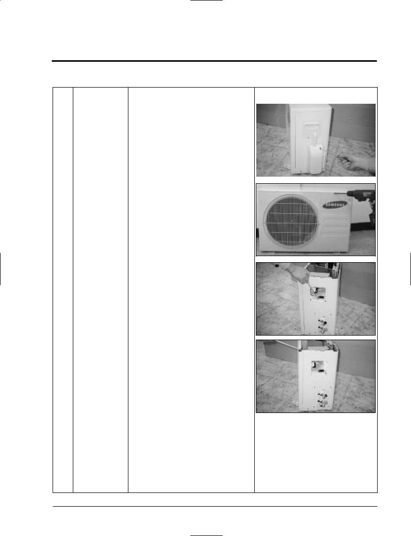
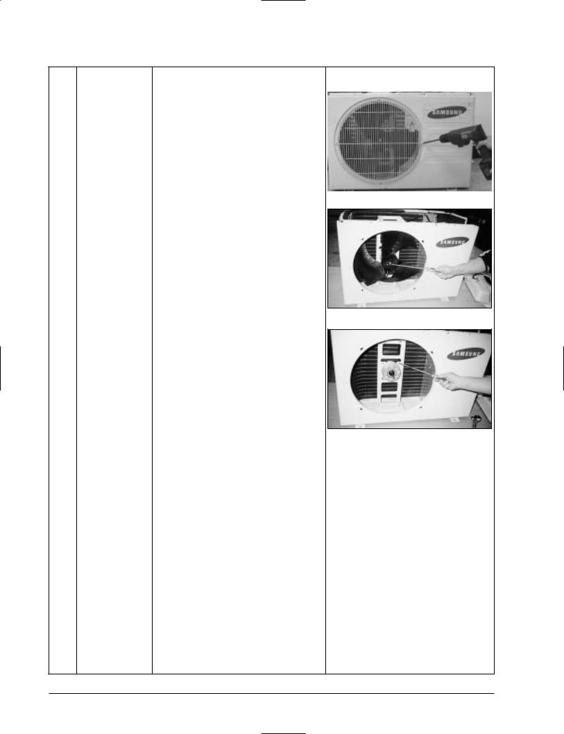
1 |
Common Work |
1) |
Loosen the fixing screw and separate |
|
|
|
|
||||
|
|
|
Handle-Cabi RH. |
|
|
|
|
2) Separate the connection wire from the |
|
|
|
|
|
|
nal block. |
|
|
|
|
|
|
|
|
3)Loosen 6 fixing screws and separate the upper cabinet.
4) Loosen the fixing screw of Ass'y E-part.
5)Loosen 5 fixing screws and separate the side cabinet.
Samsung Electronics |
4-3 |
Disassembly and Reassembly
No |
Parts |
Procedure |
Remark |
|
|
|
|
|
|
2 |
Fan-Motor |
1) Loosen 4 fixing screw of the Guard-Fan. |
|
|
|
|
|||
|
|
|
|
|
2)Remove the nut flange (Turn to the right to remove, as it is a left hand screw)
3)Separate the fan.
4)Loosen four fixing screws to separate the motor.
4-4 |
Samsung Electronics |
Disassembly and Reassembly
•SH09ZA5(6)X
•UQ09A5(6)M
•SH07ZA5(6)X
•UQ07A5(6)M
No |
Parts |
|
Procedure |
Remark |
|
|
|
|
|
|
|
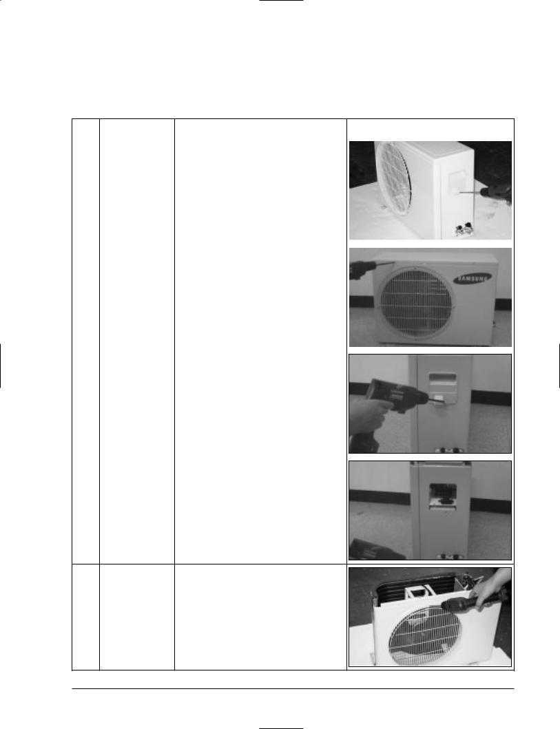
1 |
Common Work |
1) |
Loosen the fixing two screws and separate |
|
|
|
|
||||
|
|
|
the cover E-parts. |
|
|
|
|
2) |
Separate the connection wire from the ter |
|
|
|
|
|
nal block. |
|
|
|
|
3) |
Loosen five fixing screws and separate the |
|
|
|
|
|
|
||
|
|
|
|
||
|
|
|
cabi Upper. |
|
|
|
|
|
|
|
|
4) Loosen two fixing screws of Ass'y E-part.
5)Loosen nine fixing screws and separate the cabi side.
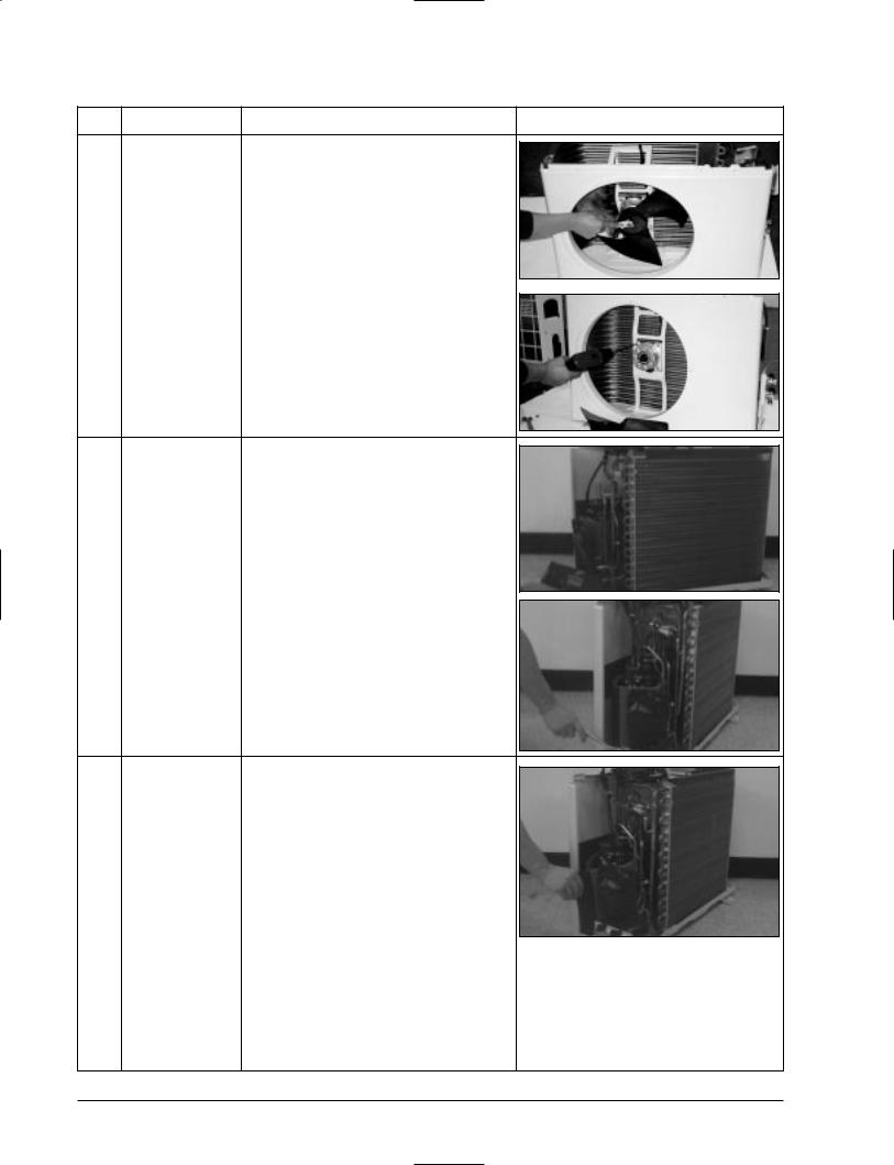
2 |
Fan and Motor |
1) |
Do “1”, above. |
|
|
2) |
Loosen four screws and seperaate Guard Fan |
|
|
|
from front cabinet |
Samsung Electronics |
4-5 |
Disassembly and Reassembly
No |
Parts |
Procedure |
Remark |
2)Remove the nut flange (Turn to the right to remove, as it is a left hand screw)
3)Separate the fan.
4)Loosen four fixing screws to separate the motor.
3 |
Heat Exchanger |
1) Do “1”, 2 above. |
|
|
|
2) |
Loosen two fixing screws of left and right |
|
|
|
side. |
|
|
3) |
Disassemble the inlet and outlet pipe by |
|
|
|
welding. |
|
|
4) |
Separate the heat exchanger. |
4 |
Compressor |
1) Do “1”, above. |
|
|
|
2) |
Loosen the nut on the terminal cover and |
|
|
|
open the terminal cover. |
|
|
3) |
Disassemble the inlet and outlet pipe of com- |
|
|
|
pressor by welding. |
|
|
4) |
Disassemble the inlet and outlet pipe of con- |
|
|
|
denser by welding |
|
|
5) Loosen the three bolts of the lower part. |
|
|
|
6) separate the compressor. |
|
4-6 |
Samsung Electronics |
 Loading...