


Samsung AQV12NSBN, AQV12NSDX, AQV09NSDX, AQV12NSD, AQV09NSD Service Manual
...SPLIT-TYPEAIR CONDITIONER
INDOOR UNIT |
OUTDOOR UNIT |
Basic : AQV09NSBN |
|
AQV12NSBN |
|
Model: AQV09NSD |
|
AQV12NSD |
|
Model Code : AQV09NSD |
AQV09NSDX |
AQV12NSD |
AQV12NSDX |
AIR CONDITIONER |
|
|
THE FEATURE OF PRODUCT |
|
|
|
|
|
|
|
|
Air Conditioner
 Simple Flat Grille Design
 good'sleep Mode
: good'sleep Mode can help you sleep quickly and soundly and wake up refreshed.
AQV09NSD/AQV12NSD
 Multi Functional Cleaning System
: Silver Nano Health System and Deodorizing/
Catechin Filter are adopted.
 Silence Mode
: When you use the "Silence Mode", you can experience extremely quiet operation of your air conditioner.
AQV09NSDX/AQV12NSDX
Refer to the service manual in the GSPN(see the rear cover) for the more information.

Operating Instructions and Installation
Contents
11. Precautions ........................................................................................................................................ |
1-1 |
1-1 Installing the air conditioner .......................................................................................................... |
1-1 |
1-2 Power supply and circuit breaker .................................................................................................. |
1-1 |
1-3 During operation .............................................................................................................................. |
1-1 |
1-4 Disposing of the unit ....................................................................................................................... |
1-2 |
1-5 Others ................................................................................................................................................. |
1-2 |
12. Product Specifications ............................................................................................................... |
2-1 |
2-1 The Feature of Product .................................................................................................................... |
2-1 |
2-2 Product Specifications ..................................................................................................................... |
2-2 |
2-3 The Comparative Specifications of Product ................................................................................ |
2-4 |
2-4 Accessory and Option Specifications ..................................................................................................... |
2-6 |
13. Alignment and Adjustments ................................................................................................. |
3-1 |
3-1 Test Mode ........................................................................................................................................... |
3-1 |
3-2 Indoor Display Error and Check Method ..................................................................................... |
3-2 |
3-3 Outdoor LED Error Display and Check Method .......................................................................... |
3-3 |
3-4 Setting Option Setup Method ....................................................................................................... |
3-4 |
14. |
Disassembly and Reassembly .............................................................................................. |
4-1 |
|
4-1 Indoor Unit ......................................................................................................................................... |
4-2 |
|
4-2 Outdoor Unit .................................................................................................................................... |
4-5 |
15. |
Exploded Views and Parts List ............................................................................................. |
5-1 |
|
5-1 Indoor Unit ......................................................................................................................................... |
5-1 |
|
5-2 Outdoor Unit ..................................................................................................................................... |
5-4 |
|
5-3 Ass’y Control In ................................................................................................................................. |
5-7 |
|
5-4 Ass’y Control Out .............................................................................................................................. |
5-9 |
16. |
Electrical Parts List ....................................................................................................................... |
6-1 |
17. |
Wiring Diagram .............................................................................................................................. |
7-1 |
|
7-1 Indoor Unit ......................................................................................................................................... |
7-1 |
|
7-2 Outdoor Unit .................................................................................................................................... |
7-2 |
18. |
Schematic Diagram ...................................................................................................................... |
8-1 |
|
8-1 Indoor Unit ......................................................................................................................................... |
8-1 |
|
8-2 Outdoor Unit .................................................................................................................................... |
8-2 |
Samsung Electronics |
1 |

Operating Instructions and Installation
Contents
19. |
Circuit Descriptions ...................................................................................................................... |
9-1 |
|
9-1 PCB Circuit Descriptions .................................................................................................................. |
9-1 |
|
9-2 Refrigerating Cycle Diagram .......................................................................................................... |
9-3 |
10. |
PCB Diagram ..................................................................................................................................... |
10-1 |
|
10-1 Indoor PCB ....................................................................................................................................... |
10-1 |
|
10-2 Outdoor PCB ................................................................................................................................... |
10-2 |
11. |
Operating Instructions .............................................................................................................. |
11-1 |
|
11-1 Name of Each Part .......................................................................................................................... |
11-1 |
|
11-2 Wireless Remote Control-Buttons and Display ........................................................................ |
11-3 |
|
11-3 Main Function ................................................................................................................................. |
11-4 |
12. |
Troubleshooting ............................................................................................................................ |
12-1 |
|
12-1 Items to be checked first ............................................................................................................... |
12-1 |
|
12-2 Fault Diagnosis by Symptom ....................................................................................................... |
12-2 |
|
12-3 PCB Inspection Method ................................................................................................................ |
12-20 |
|
12-4 Main Part Inspection Method ...................................................................................................... |
12-22 |
13. |
Block Diagram ................................................................................................................................. |
13-1 |
|
13-1 Indoor Unit ...................................................................................................................................... |
13-1 |
|
13-2 Outdoor Unit ................................................................................................................................... |
13-3 |
14. |
Reference Sheet .............................................................................................................................. |
14-1 |
|
14-1 Index for Model Name .................................................................................................................. |
14-1 |
|
14-2 Low Refrigerant Pressure Distribution ....................................................................................... |
14-2 |
|
14-3 Pressure & Capacity mark ............................................................................................................. |
14-3 |
|
14-4 Q & A for Non-trouble ................................................................................................................... |
14-4 |
|
14-5 Cleaning/Filter Change ................................................................................................................. |
14-7 |
|
14-6 Installation ....................................................................................................................................... |
14-9 |
|
14-7 Installation Diagram of Indoor Unit and Outdoor Unit .......................................................... |
14-10 |
2 |
Samsung Electronics |
1. Precautions
1-1 Installing the air conditioner
O Users should not install the air conditioner by themselves.
Ask the dealer or authorized company to install the air conditioner except the window-type air conditioner in U.S.A and Canada.
O If you don’t install the air conditioner properly, it may cause a fire, a water leakage or an electric shock.
O You must install the air conditioner according to the national wiring regulations and safety regulations.
O Install the indoor unit higher than 8.2ft(2.5m) from the floor to avoid the injury caused by the operation of the fan. (except the window-type air conditioner)
O The manufacturer is not responsible for any accidents or injury caused by an incorrect installation.
O When installing the built-in type air conditioner, keep all electric cables such as the power cable and the connection cord in pipes, ducts, or cable channels to protect them from the danger of impact or any other incidents.
1-2 Power supply and circuit breaker
O If the power cord of the air conditioner is damaged, it must be replaced by the manufacturer or a qualified person in order to avoid a hazard.
OThe air conditioner must be plugged into an independent circuit if applicable or connect the power cable to the auxiliary circuit breaker.
An all pole disconnection from the power supply must be incorporated in the fixed wiring with a contact opening of >0.12inch(3mm).
ODo not extend an electric cord to the air conditioner.
O The air conditioner must be plugged in after you complete the installation.
1-3 During operation
ODo not repair the air conditioner at your discretion.
It is recommended to contact a service center directly.
ONever spill any kind of liquid on the air conditioner.
If this happens, turn off the air conditioner and contact an authorized service center.
ODo not insert anything between the airflow blades to prevent damage of the inner fan and consequent injury. Keep children away from the air conditioner.
O Do not place any obstacles in front of the air conditioner.
ODo not spray any kind of liquid into the indoor unit. If this happens, turn off the air conditioner and contact a service center.
OMake sure that the air conditioner is well ventilated at all times: Do not place a cloth or other materials over it.
ORemove the batteries if you don’t use the remote control for a long time. (If applicable)
OUse the remote control within 23ft(7m) from the indoor unit. (If applicable)
Samsung Electronics |
1-1 |
1-4 Disposing of the unit
O Before throwing out the air conditioner, remove the batteries from the remote control.
O When you dispose of the air conditioner, consult your dealer. If pipes are removed incorrectly, refrigerant may blow out and cause air pollution. When it contacts with your skin, it can cause skin injury.
O The package of the air conditioner should be recycled or disposed of properly for environmental reasons.
1-5 Others
O Never store or load the air conditioner upside down or sideways to prevent the damage to the compressor.
O Young children or infirm persons should be always supervised when they use the air conditioner.
O Max current is measured according to IEC standard for safety.
O Current is measured according to ISO standard for energy efficiency.
1-2 |
Samsung Electronics |

2. Product Specifications
2-1 The Feature of Product
Q High Energy Efficiency BLDC Air Conditioner
BLDC Technique arises the efficiency of air conditioner and makes a room cool and warm with high energy saving.
Q Simple Flat Grille Design
With a Smart and fashionable style, the high impressive interior design allow this product to set place in anywhere.
Q good'sleep Mode
good'sleep Mode can help you sleep quickly and soundly and wake up refreshed.
Q Multi functional cleaning system
With Silver Nano Health System and Deodorizing/Catechin Filters makes your room more refreshed.
Q Silence Mode
When you use the “Silence Mode”, you can experience extremely quiet operation of your air conditioner.
Samsung Electronics |
2-1 |
Item |
|
|
|
|
Model |
AQV09NSD |
AQV12NSD |
||||
|
|
|
|
|
Indoor Unit |
|
Outdoor Unit |
Indoor Unit |
|
Outdoor Unit |
|
|
Type |
|
|
Wall-mounted |
Wall-mounted |
||||||
|
Capacity |
|
Cooling |
|
Btu/hr |
3,300/9,000/10,800 |
3,300/12,000/13,200 |
||||
|
|
Heating |
|
(Low / Std / Max) |
3,300/12,000/15,000 |
3,300/13,600/17,500 |
|||||
|
|
|
|
||||||||
|
Running Frequency |
|
Cooling |
|
Hz |
20/52/61 |
20/76/81 |
||||
|
|
Heating |
|
(Low / Std / Max) |
20/71/85 |
20/80/95 |
|||||
|
|
|
|
||||||||
|
Dehumidifying |
|
ℓ/h |
|
1.0 |
|
1.4 |
||||
Performance |
Air Volume |
|
Cooling |
|
/min |
5.9/6.8/7.69 |
|
28 |
6.4/9.3/8.18 |
|
28 |
|
Heating |
|
(H/M/L) |
7.1/8.0/8.89 |
|
27 |
7.6/8.5/9.35 |
|
27 |
||
|
|
|
|
|
|
||||||
|
Noise |
|
Cooling |
|
dB |
41 |
|
51 |
43 |
|
53 |
|
|
Heating |
|
(H/L) |
41 |
|
51 |
43 |
|
53 |
|
|
|
|
|
|
|
||||||
|
SEER |
|
Cooling |
|
(Std) |
|
19 |
|
18 |
||
|
HSPF |
|
Heating |
|
|
9.5 |
|
8.5 |
|||
|
|
|
|
|
|
||||||
|
Power |
|
|
ph-V-Hz |
1-208/230-60 |
1-208/230-60 |
|||||
|
Power Consumtion |
|
Cooling |
|
W |
240/690/840 |
240/1090/1200 |
||||
|
|
Heating |
|
(Low / Std / Max) |
220/970/1300 |
220/1170/1550 |
|||||
|
|
|
|
||||||||
|
Operating Current |
|
Cooling |
|
A |
1.5/3.3/4.0 |
1.5/5.2/5.7 |
||||
|
|
Heating |
|
(Low / Std / Max) |
1.3/4.7/6.0 |
1.3/5.5/7.0 |
|||||
|
|
|
|
||||||||
Power |
Power Factor |
|
Cooling |
|
% |
70 / 85 / 90 |
70/85/90 |
||||
|
|
Heating |
|
(Low / Std / Max) |
70 / 85 / 90 |
70/85/90 |
|||||
|
|
|
|
||||||||
|
Breaker Size |
|
A |
|
10 |
|
10 |
||||
|
|
|
MCA |
|
|
|
9.02 |
|
9.02 |
||
|
|
|
MOP |
|
|
|
15 |
|
15 |
||
|
Outer Dimension |
|
Width x Height |
|
inch |
32.5 X 11.2 X 7.4 |
|
31.1 x 21.6 x 11.2 |
32.5 X 11.2 X 7.4 |
|
31.1 x 21.6 x 11.2 |
|
|
x Depth |
|
mm |
825 X 285 X 189 |
|
790 x 548 x 285 |
825 X 285 X 189 |
|
790 x 548 x 285 |
|
|
|
|
|
|
|
||||||
Size |
Weight (Net) |
|
lb |
17.2 |
|
71.9 |
17.2 |
|
71.9 |
||
|
kg |
7.8 |
|
32.6 |
7.8 |
|
32.6 |
||||
|
|
|
|
|
|
|
|||||
|
Drain Hose |
|
D(inch) x L(ft) |
Φ0.7 x 1.8 |
Φ0.7 x 1.8 |
||||||
|
|
D(mm) x L(mm) |
Φ18 x 550 |
Φ18 x 550 |
|||||||
|
|
|
|
|
|||||||
|
|
|
Type |
|
|
Rotary, G4C090LUDER |
Rotary, G4C090LUDER |
||||
|
Motor |
|
|
Type |
Hermetic |
Hermetic |
|||||
Compressor |
|
Rated Output |
|
W |
853W |
853W |
|||||
|
|
|
|||||||||
|
|
|
Oil Type |
|
|
FREOLα68ES-T |
FREOLα68ES-T |
||||
|
RLA |
|
|
A |
|
7.0 |
|
7.0 |
|||
|
|
|
|
|
|
|
|
|
|
|
|
Blower |
|
|
|
Type |
Resin / Steel, AC |
|
Resin / Steel, DC |
Resin / Steel, AC |
|
Resin / Steel, DC |
|
Motor |
|
Rated Output |
|
W |
27 |
|
25 |
27 |
|
25 |
|
|
|
|
|
|
|||||||
|
|
|
|
|
FLA |
0.17A 35W |
|
0.10A 31W |
0.17A 35W |
|
0.10A 31W |
|
Maximum Spec. |
|
Length |
|
ft (m) |
49.2 (15) |
49.2 (15) |
||||
|
|
Height |
|
ft (m) |
26.2 (8) |
26.2 (8) |
|||||
|
|
|
|
||||||||
Piping |
|
|
Liquid |
|
OD(inch) x L(ft) |
Φ1/4 x 24.6 |
Φ1/4 x 24.6 |
||||
Refrigerant Pipe |
|
|
OD(mm) x L(m) |
Φ6.35 x 7.5 |
Φ6.35 x 7.5 |
||||||
|
|
|
|
||||||||
|
|
Gas |
|
OD(inch) x L(ft) |
Φ3/8 x 24.6 |
Φ3/8 x 24.6 |
|||||
|
|
|
|
||||||||
|
|
|
|
OD(mm) x L(m) |
Φ9.52 x 7.5 |
Φ9.52 x 7.5 |
|||||
|
|
|
|
|
|||||||
|
Heat Exchanger |
|
|
2 Row 14 Step |
|
1 Row 24 Step |
2 Row 14 Step |
|
1 Row 24 Step |
||
|
Refrigerant Control Unit |
|
|
|
EEV |
|
EEV |
||||
|
Freezer Oil Capacity |
|
|
gal |
|
0.08 |
|
0.08 |
|||
|
|
|
cc |
|
320 |
|
320 |
||||
|
|
|
|
|
|
|
|||||
Refrigerant to be Charged (R410A) |
|
oz |
|
31.7 |
|
31.7 |
|||||
|
g |
|
900 |
|
900 |
||||||
|
|
|
|
|
|
|
|||||
Refrigerant to be Added (R410A) |
|
oz/ft |
Chargeless |
Chargeless |
|||||||
|
g/m |
Chargeless |
Chargeless |
||||||||
|
|
|
|
|
|||||||
|
Protection Device (OLP) |
|
|
None |
None |
||||||
|
Cooling Test Condition |
|
|
Indoor Unit : DB80°F WB67°F |
Outdoor Unit : DB95°F WB75°F |
||||||
|
|
|
Indoor Unit : DB26.7°C WB19.4°C |
Outdoor Unit : DB35°C WB23.9°C |
|||||||
|
|
|
|
|
|
||||||
|
Heating Test Condition |
|
|
Indoor Unit : DB70°F WB60°F |
Outdoor Unit : DB47°F WB43°F |
||||||
|
|
|
Indoor Unit : DB21.1°C WB15.6°C |
Outdoor Unit : DB8.3°C WB6.1°C |
|||||||
|
|
|
|
|
|
||||||
|
|
|
|
|
indoor |
61°F to 90°F approx. |
61°F to 90°F approx. |
||||
|
|
|
|
|
16°C to 32°C approx. |
16°C to 32°C approx. |
|||||
|
|
|
cooling |
|
|
||||||
|
|
|
|
Outdoor |
14°F to 115°F approx. |
14°F to 115°F approx. |
|||||
|
|
|
|
|
|||||||
|
|
|
|
|
-10°C to 46°C approx. |
-10°C to 46°C approx. |
|||||
Operation conditon range |
|
|
|
|
|||||||
|
|
|
indoor |
80°F or less |
80°F or less |
||||||
|
|
|
|
|
|||||||
|
|
|
|
|
27°C or less |
27°C or less |
|||||
|
|
|
heating |
|
|
||||||
|
|
|
|
Outdoor |
5°F to 75°F approx. |
5°F to 75°F approx. |
|||||
|
|
|
|
|
|||||||
|
|
|
|
|
-15°C to 24°C approx. |
-15°C to 24°C approx. |
|||||
|
|
|
|
|
|
||||||
2-2 |
Samsung Electronics |

1 |
3 |
Samsung Electronics |
2-3 |

Operating Instructions and Installation
2-4 Accessory and Option Specifications
2-4-1 Accessories
Item |
Descriptions |
Code-No. |
Q'TY |
Remark |
Ass'y Plate Hanger |
DB7-02851B |
1 |
|
|
|
Remote Control |
DB93-05083P |
1 |
|
|
|
|
|
|
|
|
|
|
|
|
|
|
|
|
|
|
Batteries for Remote Control |
DB47-90024A |
2 |
Indoor
Unit


 M IST M AN M ANU G EBRA
ARUOEUUCALWNZUHLDNAISOD'EULANERTNDIII'SLNWPEISESTIENINRAISSRSLTTUUTIO'RUNR‚ÍUNSEGUOSCCTCIOIONNSES 
User’s Manual |
DB98-29981A |
1 |
GMEMBAIRASNMNTUARAUUOEUNCALWZUHLDNIASAOD'UELERNTDIPNILI'SWNEISESIENINTARISSRSTLTUUTIR'UONR‚ÍUNSEGUOCSCTCIOIONNSE S |
|
|
|
Installation Manual |
DB98-29790A |
1 |
|
|
|
|
|
|
|
|
|
GMEMBAIRASNMNTUARAUUOEUNCALWZUHLDNIASOD'UELAERNTDINIIS'LIWNPESESTIENINARISSRSTLTUUTIR'OUNR‚ÍUNSEGUOCSCTCIOIONNSE S |
|
|
|
Service Manual |
DB98-30185A |
1 |
|
|
|
|
|
2-4 |
Samsung Electronics |

DB73-20134A
Option
Samsung Electronics |
2-5 |
 and Installation
Accessories(cont.)
Item |
Descriptions |
Code-No. |
Q'TY |
Remark |
Rubber Leg |
DB73-00182A |
4 |
Pipe Clamps A |
DB39-20224A |
3 |
Pipe Clamps B |
DB39-20224B |
3 |
Cement Nail |
- |
6 |
Option |
|
M4x25 Tapping Screws |
6002-000540 |
6 |
Drain Hose, length 2m(78.7inch) |
DB62-00487A |
1 |
Putty 100g |
DB98-10568A |
1 |
2-6 |
Samsung Electronics |

"MJHONFOU BOE "EKVTUNFOUT
5FTU .PEF
)PX UP 0QFSBUF 5FTU .PEF
1SFTTUIF1PXFSCVUUPOPGJOEPPSVOJU GPS TFDPOET
$PPMJOHUFTUPQFSBUJPO
0SQSFTTUIF, TXJUDIPGUIFEJTQMBZCPBSEPODF
$PPMJOHUFTUPQFSBUJPO PSUXJDF )FBUJOHUFTUPQFSBUJPO
BGUFSSFNPWJOHUIF$PWFS$POUSPMPGPVUEPPSVOJU
5IF6OJUPQFSBUFT5FTU.PEF GPSTJYUZNJOVUFT
)PX UP $IFDL UIF 6OJU PO 5FTU .PEF
1MFBTFDIFDLUIFUISFF-&%BOE&SSPS.PEF%JTQMBZ
1MFBTFDIFDLUIFMPXQSFTTVSF BTDPOOFDUJOHBNBOJGPMEHBVHF
XJUIUIFTFSWJDFWBMWF
)PX UP 2VJU5FTU .PEF
1SFTTUIFQPXFSCVUUPOPGJOEPPSVOJUPODFBHBJO
0SQSFTTUIF, TXJUDIPGEJTQMBZCPBSEUISFFUJNFTBHBJO
"GUFSUIFUFTUPQFSBUJPOJTGJOJTIFE ZPVDBOOPUSFUSZUIFUFTU
PQFSBUJPOXJUIPVUQPXFSSFTFU5IFCMBEFQMBDFTUPTFUQPTJUJPOBOEUIFOUIFJOEPPSGBOPQFSBUFT5IF$PNQSFTTPSJTPQFSBUFECZSBUFEGSFRVFODZCFGPSFTJYUZNJOVUFTPSFOGPSDFETUPQ
PO PGGTXJUDI |
Samsung Electronics |
3-1 |

3-2 Indoor Display Error and Check Method
|
|
LAMP |
|
|
|
||
|
|
|
|
|
|
|
|
Description |
OPERATION |
TIMER |
TURBO |
|
Main Checking Point |
||
|
|
|
|
|
|
||
|
|
|
|
|
|
|
|
|
|
|
|
|
|
|
|
|
|
|
|
|
|
|
|
Indoor unit room temperature sensor error |
|
|
|
|
3-2P |
||
(open or short) |
|
|
|
||||
|
|
|
|
|
|
|
|
|
|
|
|
|
|
|
|
Indoor unit heat exchanger temperature sensor error |
|
|
|
|
3-3P |
||
(open or short) |
|
|
|||||
|
|
|
|
|
|
|
|
|
|
|
|
|
|
|
|
Indoor fan motor malfunction |
|
|
|
|
|
|
3-4P |
|
|
|
|
|
|
|
|
EEPROM error |
|
|
|
|
Option Setting |
||
|
|
|
|
|
|
|
|
Option error |
|
|
|
|
Option Setting |
||
(option wasn’t set up or option data error) |
|
||||||
|
|
|
|
|
|
|
|
|
|
|
|
|
|
|
|
Outdoor unit error |
|
|
|
|
|
|
Remote Control on/off |
|
|
|
|
Outdoor Unit Power Reset |
|||
|
|
|
|
|
|
|
|
|
|
|
|
|
|
|
|
|
|
|
|
|
●: Lamp on, |
: Lamp off, : Lamp blink |
|
3-2 |
Samsung Electronics |

3-3 Outdoor LED Error Display and Check Method
No. |
|
LED Display |
|
Explanation |
|
|
|
|
|||
Yellow |
Green |
Red |
|||
|
|
||||
|
|
|
|
|
|
1 |
○ |
○ |
○ |
Power off/ VDD NG |
|
|
|
|
|
|
|
2 |
○ |
○ |
|
IPM Over Current(O.C) |
|
|
|
|
|
|
|
|
○ |
○ |
● |
|
|
3 |
|
|
|
Abnormal Serial communication |
|
○ |
● |
● |
|||
|
|
||||
|
|
|
|
|
|
4 |
○ |
|
○ |
Compressor Starting error |
|
|
|
|
|
|
|
5 |
○ |
|
● |
Normal Operation |
|
|
|
|
|
|
|
6 |
○ |
● |
○ |
Compressor Lock error |
|
|
|
|
|
|
|
7 |
○ |
● |
|
DC-Link voltage under/over error |
|
|
|
|
|
|
|
8 |
|
○ |
|
Outdoor temperature sensor error |
|
|
|
|
|
|
|
9 |
|
○ |
● |
Discharge over temperature |
|
|
|
|
|
|
|
10 |
|
|
○ |
Discharge temperature sensor error |
|
|
|
|
|
|
|
11 |
|
|
● |
Current sensor error |
|
|
|
|
|
|
|
12 |
|
● |
○ |
Compressor limit error |
|
|
|
|
|
|
|
13 |
|
● |
|
Coil temperature sensor error |
|
|
|
|
|
|
|
14 |
|
● |
● |
1min. Time out Communication |
|
|
|
|
|
|
|
15 |
● |
○ |
○ |
Fan error |
|
|
|
|
|
|
|
16 |
● |
○ |
|
OTP error |
|
|
|
|
|
|
|
17 |
● |
○ |
● |
Compressor rotation error |
|
|
|
|
|
|
|
18 |
● |
|
○ |
Operation condition secession(Dual only) |
|
|
|
|
|
|
|
19 |
● |
|
|
DC-Link voltage sensor error |
|
|
|
|
|
|
|
20 |
● |
|
● |
I_Trip error / PFC Over current |
|
|
|
|
|
|
|
21 |
● |
● |
○ |
GAS Leak error |
|
|
|
|
|
|
|
22 |
● |
● |
|
AC Line Zero Cross Signal out |
|
|
|
|
|
|
|
23 |
● |
● |
● |
Power ON reset(1sec) |
|
|
|
|
|
|
|
24 |
|
○ |
○ |
Capacity miss match |
|
|
|
|
|
|
|
25 |
○ |
|
|
Test Operation at Cooling Mode |
|
|
|
|
|
|
|
26 |
|
|
|
Test Operation at Heating Mode |
|
|
|
|
|
|
●: LED ON, ○: LED OFF, : LED BLINK
Samsung Electronics |
3-3 |
4FUUJOH 0QUJPO 4FUVQ .FUIPE
FY 0QUJPO /P 


4UFQ &OUFS UIF 0QUJPO 4FUVQ NPEF
|
TU |
5BLFPVUUIFCBUUFSJFTPGSFNPUFDPOUSPM |
|
|
OE |
1SFTTUIFUFNQFSBUVSF CVUUPOTJNVMUBOFPVTMZBOEJOTFSU |
|
|
|
UIFCBUUFSZBHBJO |
|
|
SE |
.BLFTVSFUIFSFNPDPOEJTQMBZTIPXOBT |
|
4UFQ &OUFS UIF 0QUJPO 4FUVQ NPEF BOE TFMFDU ZPVS PQUJPO BDDPSEJOH UP UIF GPMMPXJOH QSPDFEVSF


64FUUJOHJTOPUSFRVJSFEJGZPVNVTU  BWBMVFXIJDIIBTB EFGBVMU
5IFEFGBVMUWBMVFJT 


0UIFSXJTF QVTIUIF CVUUPOUP 
 &WFSZUJNFZPVQVTIUIFCVUUPO UIFEJTQMBZQBOFMSFBET PS
 SFQFBUFEMZ
1VTIUIF CVUUPOUPTFUUIFEJTQMBZQBOFMUP 
 &WFSZUJNFZPVQVTIUIFCVUUPO UIFEJTQMBZQBOFMSFBET ° °
° °
°  °
° °
° °
° °
° °
° °
°
 SFQFBUFEMZ
1VTIUIF CVUUPOUPTFUUIFEJTQMBZQBOFMUP 
&WFSZUJNFZPVQVTIUIFCVUUPO UIFEJTQMBZQBOFMSFBET ° °
° °  °
° °
° °
° °
° °
° °
° SFQFBUFEMZ
1VTIUIF CVUUPOUPTFUUIFEJTQMBZQBOFMUP  &WFSZUJNFZPVQVTIUIFCVUUPO UIFEJTQMBZQBOFMSFBET ° °
° °  °
° °
° °
° °
° °
° °
° SFQFBUFEMZ
1VTIUIF CVUUPOUPTFUUIFEJTQMBZQBOFMUP  &WFSZUJNFZPVQVTIUIFCVUUPO UIFEJTQMBZQBOFMSFBET ° °
° °  °
° °
° °
° °
° °
° °
° SFQFBUFEMZ
1VTIUIF CVUUPOUPTFUUIFEJTQMBZQBOFMUP  &WFSZUJNFZPVQVTIUIFCVUUPO UIFEJTQMBZQBOFMSFBET ° °
° °  °
° °
° °
° °
° °
° °
° SFQFBUFEMZ
|
4BNTVOH&MFDUSPOJDT |
"MJHONFOU BOE "EKVTUNFOUT
1SFTT CVUUPO UIFOUIFEFGBVMUWBMVFJT 


1VTIUIF CVUUPOUPTFUUIFEJTQMBZQBOFMUP 
&WFSZUJNFZPVQVTIUIFCVUUPO UIFEJTQMBZQBOFMSFBET ° °
|
° ° ° ° ° ° ° ° SFQFBUFEMZ |
|
|
||
|
1VTIUIF CVUUPOUPTFUUIFEJTQMBZQBOFMUP 
|
|
&WFSZUJNFZPVQVTIUIFCVUUPO UIFEJTQMBZQBOFMSFBET ° ° |
||||||||||
|
|
|
|
|
|
|
|
|
|
|||
|
|
|
|
|
|
|
|
|
|
° ° ° ° ° ° ° ° SFQFBUFEMZ |
||
|
|
|
|
|
|
|
|
|
|
|||
|
|
|||||||||||
|
|
|
|
|||||||||
|
|
1VTIUIF CVUUPOUPTFUUIFEJTQMBZQBOFMUP |
||||||||||
|
||||||||||||
|
|
|
|
|
|
|
|
|
|
|||
|
|
|
|
|
|
|
|
|
|
&WFSZUJNFZPVQVTIUIFCVUUPO UIFEJTQMBZQBOFMSFBET ° ° |
||
|
|
|
|
|
|
|
|
|
|
° ° ° ° ° ° ° ° SFQFBUFEMZ |
||
|
|
|
|
|
|
|
|
|
|
|||
|
|
|
|
|
|
|
|
|
|
|||
|
|
|
|
|
|
|
|
|
|
|||
|
|
|
|
|
|
|
|
|
|
|
|
|
|
|
|
|
|
|
|
|
|
|
1VTIUIF CVUUPOUPTFUUIFEJTQMBZQBOFMUP |
||
|
|
|
|
|
|
|
|
|
|
|||
|
|
|
|
|
|
|
|
|
|
|
|
|
|
|
|
|
|
|
|
|
|
|
&WFSZUJNFZPVQVTIUIFCVUUPO UIFEJTQMBZQBOFMSFBET ° ° |
||
|
|
|
|
|
|
|
|
|
|
° ° ° ° ° ° ° ° SFQFBUFEMZ |
||
|
|
|
|
|
|
|
|
|
|
|
|
|
|
|
|
|
|
|
|
|
|
|
1VTIUIF CVUUPOUPTFUUIFEJTQMBZQBOFMUP |
||
64FUUJOHJTOPUSFRVJSFEJGZPVNVTU |
|
|||||||||||
BWBMVFXIJDIIBTB EFGBVMU |
|
&WFSZUJNFZPVQVTIUIFCVUUPO UIFEJTQMBZQBOFMSFBET ° ° |
||||||||||
|
|
|
|
|
|
|
|
|
|
° ° ° ° ° ° ° ° SFQFBUFEMZ |
||
4UFQ 6QPO DPNQMFUJPO PG UIF TFMFDUJPO DIFDL ZPV NBEF SJHIU TFMFDUJPOT
1SFTTUIF.PEF4FMFDUJPOLFZ UPTFUUIFEJTQMBZQBSUUP
 BOEDIFDLUIFEJTQMBZQBSU
°5IFEJTQMBZQBSUTIPXT 


1SFTTUIF.PEF4FMFDUJPOLFZ UPTFUUIFEJTQMBZQBSUUP  BOEDIFDLUIFEJTQMBZQBSU
°5IFEJTQMBZQBSUTIPXT 

4UFQ 1SFTTJOH UIF 0/ 0'' CVUUPO
8IFOQSFTTJOHUIFPQFSBUJPO0/ 0''LFZXJUIUIFEJSFDUJPOPGSFNPUFDPOUSPMGPSVOJU UIFTPVOE %JOH PS %JSJSJOH JTIFBSEBOEUIF01&3"5*0/*$0/ MBNQPGUIFEJTQMBZJTGMJDLFSJOHBUUIFTBNFUJNF UIFOUIFJOQVUPGPQUJPOJTDPNQMFUFE
*GUIFEJSJSJOHTPVOEJTOUIFBSE USZBHBJOQSFTTJOHUIF0/ 0''CVUUPO
4UFQ 6OJU PQFSBUJPO UFTU SVO
'JSTU 3FNPWFUIFCBUUFSZGSPNUIFSFNPUFDPOUSPM
4FDPOE 3F JOTFSUUIFCBUUFSZJOUPUIFSFNPUFDPOUSPM
5IJSE 1SFTT0/ 0''LFZXJUIUIFEJSFDUJPOPGSFNPUFDPOUSPMGPSTFU
t &SSPS .PEF
TU |
*GBMMMBNQTPGJOEPPSVOJUBSFGMJDLFSJOH 1MVHPVU QMVHJOQPXFSQMVHBHBJOBOEQSFTT0/ 0''LFZUPSFUSZ |
OE |
*GUIFVOJUJTOPUXPSLJOHQSPQFSMZPSBMMMBNQTBSFDPOUJOVPVTMZGMJDLFSJOHBGUFSTFUUJOHUIFPQUJPODPEF TFFJGUIF |
|
DPSSFDUPQUJPODPEFJTTFUVQGPSJUTNPEFM |
4BNTVOH&MFDUSPOJDT |
|

AlignmentOperating InstructionsandAdjustmentsand Installation
 OPTION ITEMS
REMOCON |
SEG1 |
SEG2 |
SEG3 |
SEG4 |
SEG5 |
SEG6 |
SEG7 |
SEG8 |
SEG9 |
SEG10 |
SEG11 |
SEG12 |
|
MODEL |
|||||||||||||
|
|
|
|
|
|
|
|
|
|
|
|
||
AQV09NSDNKCV |
0 |
8 |
E |
7 |
7 |
7 |
1 |
7 |
7 |
2 |
4 |
C |
|
|
|
|
|
|
|
|
|
|
|
|
|
|
|
AQV12NSDNKCV |
0 |
9 |
E |
7 |
7 |
7 |
1 |
7 |
7 |
2 |
6 |
E |
|
|
|
|
|
|
|
|
|
|
|
|
|
|
3-6 |
Samsung Electronics |

4. Disassembly and Reassembly
QNecessary Tools
Item |
Remark |
+SCREW DRIVER
MONKEY SPANNER
Samsung Electronics |
4-1 |
4-1 Indoor Unit
No |
Parts |
Procedure |
Remark |
|
1 |
Front Grille |
1) Stop the air conditioner operation and |
|
|
|
|
|||
|
|
shut off the main power. |
|
|
|
|
|
|
|
2)Open the Front Grille by pulling right and left sides of the hook.
3) Loosen 1 of the right screw(CCW) and detach the Terminal Cover. (Use +Screw Driver.)
4) Detach the thermistor from the Front Grille.
5) Loosen 2 fixing screws(CCW) of Front Grille.
6) Unlock 3 hooks to fix Panel Front and Tray Drain. (Use +Screw Driver.)
4-2 |
Samsung Electronics |
Disassembly and Reassembly
No |
Parts |
Procedure |
Remark |
7)Unlock 3 hooks to fix Panel Front and Back-Body.
2Control-In 1) Take all the connector of PCB upper side out.
(Main PCB) |
(Inclusion Power Cord) |
2) |
Detach the outdoor unit connection wire from |
|
the Terminal Block. |
3) |
Loosen 4 fixing screws(CCW) of Ass'y |
|
Control-In. (Use +Screw Driver.) |
|
You can disassembly Ass'y Control In |
|
without evaporator disassembled. |
3 |
Tray Drain |
1) Pull Tray Drain out from the Back Body. |
Samsung Electronics |
4-3 |
Disassembly and Reassembly
No |
Parts |
|
Procedure |
Remark |
|
4 |
Heat Exchanger |
1) |
Loosen 2 fixing earth screws(CCW) of right |
|
|
|
|
||||
|
|
|
side. (Use +Screw Driver.) |
|
|
|
|
2) |
Detach the Connection Pipe. |
|
|
|
|
3) |
Detach the Holder Pipe at the rear side. |
|
|
|
|
|
|
|
|
4) Loosen the 4 fixing screws(CCW) of right and left side. (Use +Screw Driver.)
5) Lifting the Heat Exchanger up a little to push the up side for separation from the indoor unit.
 First, check Comp. Down and then disconnect the connection pipes before you disassemble the Evaporator from indoor unit.
5 |
Fan Motor |
1) |
Loosen the fixing screw(CCW). |
|
& |
|
(Use +Screw Driver.) |
|
Cross Fan |
2) |
Detach the Fan Motor from the Fan. |
|
|
3) |
Detach the Fan From the left Holder Bearing. |
4-4 |
Samsung Electronics |
4-2 Outdoor Unit
No |
Parts |
Procedure |
Remark |
1 |
Common Work |
1) Loosen 1 fixing screw(CCW) of the Cover-Side. |
|
|
|
(Use +Screw Driver.) |
|
2)Loosen each 4 screws(CCW) on both right and left Cabinet Side edges and a fixing screw on the Cabinet Front lower to detach the Cabinet Front. (Use +Screw Driver.)
3) Detach the Cabinet Front like the picture on the right side.
4) Loosen 1 screw(CCW) fixed to assemble Plate Control Out with Cabinet-Side RH.
(Use +Screw Driver.)
Samsung Electronics |
4-5 |

Disassembly and Reassembly
No |
Parts |
Procedure |
Remark |
5) Loosen 2 fixing screws(CCW) on the rear side of Cabinet-Side RH. (Use +Screw Driver.)
6) Loosen 3 screws(CCW) fixed to assemble Bracket Valve with Cabinet-Side RH. (Use +Screw Driver.)
7)Loosen 2 fixing screws(CCW) of Cabinet Side LF. (Use +Screw Driver.)
4-6 |
Samsung Electronics |
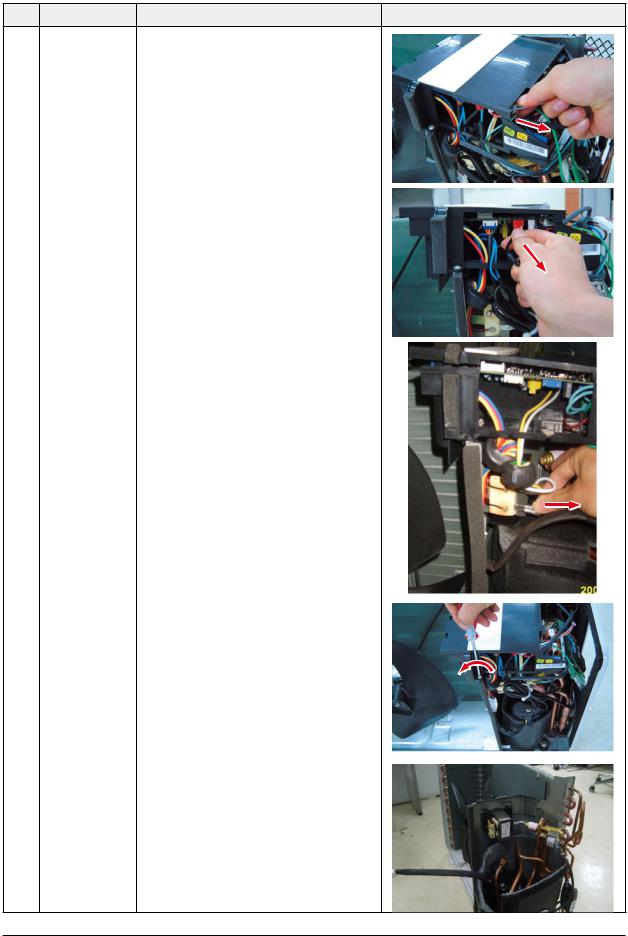
Disassembly and Reassembly
No |
Parts |
Procedure |
Remark |
2Ass’y Control Out 1) Detach the Motor Wire from the PCB of Ass’y
Control Out.
2)Detach several connectors from the PCB of Ass’ y Control Out.
3) Detach 2 Connect Wires from Reactor.
4) Loosen 1 screw(CCW) fixed to assemble Ass’y Control Out with Partition.
(Use +Screw Driver.)
Samsung Electronics |
4-7 |

Disassembly and Reassembly
No |
Parts |
|
Procedure |
Remark |
3 |
Fan |
1) Release the refrigerant at first. |
|
|
|
& |
2) |
Loosen fixing screw(CW). (Use Monkey |
|
|
Motor |
|
Spanner.) |
|
|
|
3) |
Disassemble the pipes in both inlet and outlet |
|
|
|
|
with welding torch. |
|
|
|
4) Detach the Heat Exchanger. |
|
|
4 |
Heat Exchanger 1) Loosen 2 fixing screws(CCW) on both sides. |
|
|
|
(Use +Screw Driver.) |
|
2) |
Disassemble the pipes in both inlet and outlet |
|
|
with welding torch. |
|
3) |
Detach the Heat Exchanger. |
|
|
Before you disassemble the pipes and |
|
|
Condenser, be sure that there should be no |
|
|
refrigerant remained in the unit. |
5 |
Ass’y Valve 4-Way |
1) Loosen 4 bolts(CCW) fixed to assemble Valve |
|
& |
Service with Bracket Valve like the picture on |
|
Ass’y Valve EEV |
the right side. (Use Monkey Spanner.) |
|
|
2) Disassemble the pipes assembled the suction |
|
|
and discharge sides of the Compressor with |
|
|
welding torch. |
6 |
Compressor |
1) Loosen the Nut(CCW) of Terminal Cover. (Use |
|
|
Monkey Spanner.) |
|
|
2) Detach the Terminal Cover and detach the |
|
|
Connect Comp Wire from Compressor. |
|
|
3) Disassemble the Felt Comp Sound. |
|
|
4) Loosen the 3 bolts(CCW) at the bottom of |
|
|
Compressor like the picture on the right side. |
|
|
(Use Monkey Spanner.) |
4-8 |
Samsung Electronics |

5. Exploded Views and Parts List
5-1 Indoor Unit
 3
3
 3-1
3-1
2 |
|
0 |
|
2-1 |
1 |
|
|
|
|
|
|
|
|
|
|
|
|
|
|
|
|
|
|
|
|
|
|
|
|
|
|
|
|
|
|
|
|
|
|
|
|
|
|
|
|
|
|
|
|
|
|
|
|
|
|
|
|
|
|
|
|
|
|
|
|
|
|
|
|
|
|
|
|
|
|
|
|
|
|
|
|
|
|
|
|
|
|
|
|
|
|
|
|
|
|
|
|
|
|
|
|
|
|
|
|
|
|
|
|
|
|
|
|
|
|
|
|
|
|
|
|
|
|
|
|
|
|
|
|
|
|
|
|
|
|
|
|
|
|
|
|
|
|
|
|
|
|
|
|
|
|
|
|
|
|
|
|
|
|
|
|
|
|
|
|
|
|
|
|
|
|
|
|
|
|
|
|
|
|
|
|
|
|
|
|
|
|
|
|
|
|
|
|
|
|
|
|
|
|
|
|
|
|
|
|
|
|
|
|
|
|
|
|
|
|
|
|
|
|
|
|
|
|
|
|
|
|
|
|
|
|
|
|
|
|
|
|
|
|
|
|
|
|
|
|
|
|
|
|
|
|
|
|
|
|
|
|
|
|
|
|
|
|
|
|
|
|
|
|
|
|
|
|
|
|
|
|
|
|
|
|
|
|
|
|
|
|
|
|
|
|
|
|
|
|
|
|
|
|
|
|
|
|
|
|
|
|
|
|
|
|
|
|
|
|
|
|
|
|
|
|
|
|
|
|
|
|
|
|
|
|
|
|
|
|
|
|
|
|
|
|
|
|
|
|
|
|
|
|
|
|
|
|
|
|
|
|
|
|
|
|
|
|
|
|
|
|
|
|
|
|
|
|
|
|
|
|
|
|
|
|
|
|
|
|
5-1 |
|
|
|
|
|
|
|
|
|
|
|
|
|
|
|
Samsung Electronics |
||||

Operating Instructions and Installation
ASSY
2
2
DB93-05083P |
70 |
0
1
12
12-1
13
13-1
Samsung Electronics
Operating Instructions and Installation
ASSY
NA
2
2
DB93-05083P |
70 |
10
11
12
12-1
13
13-1
Samsung Electronics

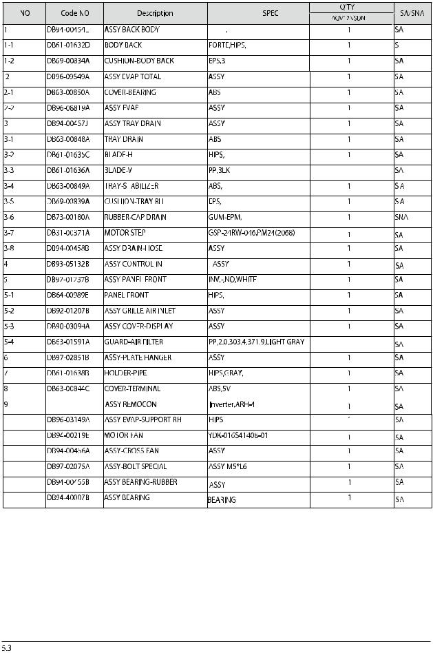
5-2 Outdoor Unit |
|
|
|
|
|
|
|
|
|
|
|
|
16 |
|
|
|
|
30 |
|
|
|
|
|
|
11 |
|
|
|
|
|
|
10 |
|
|
|
|
|
9 |
|
|
|
|
|
|
8 |
|
|
|
|
|
7 |
|
28-2 |
28 |
|
|
|
|
|
|
||
|
|
|
|
28-3 |
29-2 |
12 |
|
|
|
|
2725 |
|
29 |
|
|
|
|
|
|
|
|
|
|
20 |
28-1 |
29-1 |
|
|
|
|
|
|
|
|
|
|
|
21 |
26 |
14 |
|
|
6 |
|
22 |
|
|
|
|
5 |
|
|
|
||
15-2 15-1 |
|
23 |
|
|
||
|
|
|
|
|
||
|
|
|
17 |
|
|
31 |
|
|
|
19 |
|
13 |
|
|
|
|
|
|
|
|
15 |
|
|
|
4 |
|
|
|
|
|
18 |
|
|
|
|
|
|
|
|
|
|
|
|
|
|
24 |
|
|
|
|
|
|
3 |
|
|
2 |
|
|
1 |
|
|
|
|
|
|
|
|
|
|
Samsung Electronics |
|
|
|
|
|
5-4 |

Exploded Views and Parts List
 Parts List
|
|
|
|
Q'TY |
|
|
No. |
Code No. |
Description |
Speci cation |
AQV09NSDX |
AQV12NSDX |
SA/SNA |
|
|
|
|
|
||
|
|
|
|
|
|
|
1 |
DB90-01711Q |
ASS’Y CABI FRONT |
ASS’Y,SC-94445T |
1 |
1 |
SA |
2 |
DB94-02118B |
ASS’Y -GUARD FAN |
PP |
1 |
1 |
SA |
|
|
|
|
|
|
|
3 |
DB90-01681F |
ASS’Y BASE OUT |
ASS’Y,SC-94445T |
1 |
1 |
SA |
4 |
DB61-02068B |
ASS’Y BRACKET VALVE |
ASS’Y,SC-94445T |
1 |
1 |
SA |
5 |
DB67-00397A |
FAN-PROPELLER |
AS+G/F20%,ø400 |
1 |
1 |
SA |
6 |
DB60-30028A |
NUT-HEXAGON |
M6 |
1 |
1 |
SA |
7 |
DB31-00431A |
MOTOR FAN OUT |
AC Motor |
1 |
1 |
SA |
8 |
DB61-01644A |
BRACKET MOTOR |
SGCC-M |
1 |
1 |
SA |
|
|
|
|
|
|
|
9 |
DB97-02225A |
ASS’Y SUPPORT PLATE B/M |
SGCC-M |
1 |
1 |
SA |
10 |
DB94-01655B |
ASS’Y PARTITION |
ASS’Y,SGCC-M |
1 |
1 |
SA |
11 |
DB27-00041A |
REACTOR |
PPS,5mH,10A |
1 |
1 |
SA |
|
|
|
|
|
|
|
12 |
DB96-08373A |
ASS’Y COND UNIT |
ASS’Y |
1 |
1 |
SA |
13 |
DB90-03818F |
ASS’Y COVER CONTROL |
ASS’Y |
1 |
1 |
SA |
|
|
|
|
|
|
|
14 |
DB90-02876G |
ASS’Y CABINET SIDE RH |
ASS’Y,SC-94445T |
1 |
1 |
SA |
15 |
DB90-01713E |
ASS’Y CABINET SIDE LF |
SECC-P,SC-94445T |
1 |
1 |
SA |
15-1 |
DB64-00982A |
CABINET-SIDE LF |
ASSY ,SC-94445T |
1 |
1 |
SNA |
15-2 |
DB64-00992A |
HANDLE-LF |
PP |
1 |
1 |
SA |
16 |
DB64-02118A |
SCREEN-COND BAR |
- |
1 |
1 |
SA |
17 |
G4C090LUDER |
COMPRESSOR |
ROTARY,BLDC |
1 |
1 |
SA |
18 |
DB99-01032A |
ASSY-GROMMET |
ASSY |
3 |
3 |
SA |
19 |
DB60-30028A |
SCREW HEX |
M8 |
3 |
3 |
SA |
20 |
6021-001142 |
NUT-HEXAGON FLANGE |
M5 |
1 |
1 |
SA |
21 |
DB63-00816A |
COVER TERMINAL |
PBT(G/F 15%) |
1 |
1 |
SA |
22 |
DB63-00817A |
GASKET |
RUBBER |
1 |
1 |
SA |
23 |
DB63-01647A |
FELT COMP SIDE |
FELT+PVC Sheet |
1 |
1 |
SA |
24 |
DB63-01958A |
FELT COMP BASE |
FELT+PVC Sheet |
1 |
1 |
SA |
25 |
DB63-01710B |
FELT COMP UPPER |
FELT+PVC Sheet |
1 |
1 |
SA |
26 |
DB63-01934A |
FELT COMP SIDE OUT |
FELT+PVC Sheet |
1 |
1 |
SA |
|
|
|
|
|
|
|
27 |
DB63-02034A |
FELT COMP UPPER OUT |
FELT+PVC Sheet |
1 |
1 |
SA |
28 |
DB96-08389A |
ASS’Y VALVE 4WAY |
ASS’Y |
1 |
1 |
SA |
28-1 |
DB62-02284A |
VALVE SERVICE |
ASS’Y |
1 |
1 |
SNA |
28-2 |
DB62-02286A |
TUBE-4WAY VALVE |
ASS’Y |
1 |
1 |
SNA |
28-3 |
DB33-00002C |
SOLENOID-ASSY |
ASS’Y |
1 |
1 |
SA |
29 |
DB96-08390A |
ASS’Y-VALVE EEV |
ASS’Y |
1 |
1 |
SA |
29-1 |
DB62-02283A |
VALVE SERVICE |
ASS’Y |
1 |
1 |
SNA |
29-2 |
DB62-03964A |
EEV-COIL |
ASS’Y |
1 |
1 |
SA |
|
|
|
|
|
|
|
30 |
DB93-04345C |
ASS’Y CONTROL OUT |
ASS’Y |
1 |
- |
SA |
|
DB93-04345D |
ASS’Y CONTROL OUT |
ASS’Y |
- |
1 |
SA |
|
|
|
|
|
|
|
31 |
DB95-01358A |
ASS’Y-THERMISTOR |
ASS’Y |
1 |
1 |
SA |
5-5 |
Samsung Electronics |
 Loading...