


K-400Operator’s Manual
Drain Cleaning Machine
 WARNING
Read this Operator’s Manual |
|
carefully before using this |
|
tool. Failure to understand |
|
and follow the contents of this |
|
manual may result in electri- |
|
cal shock, fire and/or serious |
|
personal injury. |
• Français – 19 |
|
• Castellano – pág. 41 |

K-400 Drain Cleaning Machine
Table of Contents |
|
Recording Form for Machine Serial Number .............................................................................................................. |
1 |
Safety Symbols .............................................................................................................................................................. |
2 |
General Safety Rules |
|
Work Area ................................................................................................................................................................... |
2 |
Electrical Safety........................................................................................................................................................... |
2 |
Personal Safety ........................................................................................................................................................... |
2 |
Tool Use and Care ...................................................................................................................................................... |
3 |
Service ........................................................................................................................................................................ |
3 |
Specific Safety Information |
|
Drain Cleaner Safety ................................................................................................................................................... |
3 |
Description, Specifications and Standard Equipment |
|
Description .................................................................................................................................................................. |
4 |
Specifications .............................................................................................................................................................. |
4 |
Standard Equipment.................................................................................................................................................... |
5 |
Machine Assembly |
|
Installing Wheels ......................................................................................................................................................... |
5 |
Mounting AUTOFEED® (Optional Accessory) ............................................................................................................. |
5 |
Mounting Guide Hose to AUTOFEED® (Optional Accessory) ..................................................................................... |
6 |
Machine Inspection ....................................................................................................................................................... |
6 |
Machine and Work Area Set Up ................................................................................................................................... |
8 |
Operating Instructions |
|
Using Manual Feed Machine..................................................................................................................................... |
11 |
Using Machines with AUTOFEED............................................................................................................................. |
12 |
Using Machine with an AUTOFEED and a Front Guide Hose .................................................................................. |
14 |
Maintenance Instructions |
|
Cables ....................................................................................................................................................................... |
14 |
AUTOFEED............................................................................................................................................................... |
15 |
Cleaning .................................................................................................................................................................... |
15 |
Lubrication................................................................................................................................................................. |
15 |
Belt Removal/Installation........................................................................................................................................... |
15 |
Torque Limiter Adjustment ........................................................................................................................................ |
15 |
Installing Replacement Cable |
|
To remove Cable From Drum.................................................................................................................................... |
15 |
To Install Replacement Cable ................................................................................................................................... |
16 |
Accessories ................................................................................................................................................................. |
16 |
Machine Storage.......................................................................................................................................................... |
17 |
Service and Repair ...................................................................................................................................................... |
17 |
Troubleshooting .......................................................................................................................................................... |
17 |
Wiring Diagram ............................................................................................................................................................ |
18 |
Lifetime Warranty.......................................................................................................................................... |
Back Cover |
ii |
Ridge Tool Company |

 K-400
K-400
K-400
Drain Cleaning Machine
K-400 Drain Cleaner
Record Serial Number below and retain product serial number which is located on nameplate.
Serial
No.
K-400 Drain Cleaning Machine
Safety Symbols
In this operator’s manual and on the product, safety symbols and signal words are used to communicate important safety information. This section is provided to improve understanding of these signal words and symbols.
This is the safety alert symbol. It is used to alert you to potential personal injury hazards. Obey all safety messages that follow this symbol to avoid possible injury or death.

 DANGER DANGER indicates a hazardous situation which, if not avoided, will result in death or serious injury.

 WARNING WARNING indicates a hazardous situation which, if not avoided, could result in death or serious injury.

 CAUTION CAUTION indicates a hazardous situation which, if not avoided, could result in minor or moderate injury.
NOTICE |
NOTICE indicates information that relates to the protection of property. |
This symbol means read the operator’s manual carefully before using the equipment. The operator’s manual contains important information on the safe and proper operation of the equipment.
This symbol means always wear safety glasses with side shields or goggles when handling or using this equipment to reduce the risk of eye injury.
This symbol indicates the risk of hands, fingers or other body parts being caught, wrapped or crushed in the drain cleaning cable.
This symbol indicates the risk of electrical shock.
This symbol indicates the risk of entanglement in a belt and pulley.
General Safety Rules*
 WARNING
Read and understand all instructions. Failure to follow all instructions listed below may result in electric shock, fire, and/or serious injury.
SAVE THESE INSTRUCTIONS!
Work Area
•Keep work area clean and well lit. Cluttered benches and dark areas invite accidents.
•Do not operate power tools in explosive atmospheres, such as in the presence of flammable liquids, gases, or dust. Power tools create sparks which may ignite the dust or fumes.
•Keep bystanders, children, and visitors away while operating a power tool. Distractions can cause you to lose control.
Electrical Safety
•Grounded tools must be plugged into an outlet properly installed and grounded in accordance with all codes and ordinances. Never remove the grounding prong or modify the plug in any way. Do not use any adapter plugs. Check with a qualified
electrician if you are in doubt as to whether the outlet is properly grounded. If the tool should electrically malfunction or break down, grounding provides a low resistance path to carry electricity away from the user.
•Avoid body contact with grounded surfaces such as pipes, radiators, ranges and refrigerators. There is an increased risk of electric shock if your body is grounded.
•Do not expose power tools to rain or wet conditions. Water entering a power tool will increase the risk of electric shock.
•Do not abuse the cord. Never use the cord to carry the tool or pull the plug from an outlet. Keep cord away from heat, oil, sharp edges or moving parts. Replace damaged cords immediately. Damaged cords increase the risk of electric shock.
•When operating a power tool outside, use an outdoor extension cord marked “W-A” or “W”. These cords are rated for outdoor use and reduce the risk of electric shock.
Personal Safety
•Stay alert, watch what you are doing and use common sense when operating a power tool. Do not
*The text used in the General Safety Rule section of this manual is verbatim, as required, from the applicable UL/CSA 745 1st edition standard. This section contains general safety practices for many different types of power tools. Not every precaution applies to every tool, and some do not apply to this tool.
2 |
Ridge Tool Company |

K-400 Drain Cleaning Machine
use a tool while you are tired or under the influence of drugs, alcohol or medication. A moment of inattention while operating power tools may result in serious personal injury.
•Dress properly. Do not wear loose clothing or jewelry. Contain long hair. Keep your hair, clothing and gloves away from moving parts. Loose clothes, jewelry or long hair can be caught in moving parts.
•Avoid accidental starting. Be sure switch is OFF before plugging in. Carrying power tools with your finger on the switch or plugging in power tools that have the switch ON invites accidents.
•Remove adjusting keys or wrenches before turning the tool ON. A wrench or a key left attached to a rotating part of the power tool may result in personal injury.
•Do not overreach. Keep proper footing and balance at all times. Proper footing and balance enables better control of the tool in unexpected situations.
•Use safety equipment. Always wear eye protection. Safety equipment such as dust mask, non-skid safety shoes, hard hat, or hearing protection used for appropriate conditions will reduce personal injuries.
Tool Use and Care
•Use clamps or other practical way to secure and support the workpiece to a stable platform. Holding the work by hand or against your body is unstable and may lead to loss of control.
•Do not force the tool. Use the correct tool for your application. The correct tool will do the job better and safer at the rate for which it was designed.
•Do not use the power tool if the switch does not turn it ON and OFF. Any tool that cannot be controlled with the switch is dangerous and must be repaired.
•Disconnect the plug from the power source before making any adjustments, changing accessories, or storing power tools. Such preventive safety measures reduce the risk of starting the power tool accidentally.
•Store idle tools out of the reach of children and other untrained persons. Tools are dangerous in the hands of untrained users.
•Maintain tools with care. Keep cutting tools sharp and clean. Properly maintained tools with sharp cutting edges are less likely to bind and are easier to control.
•Check for misalignment or binding of moving parts, breakage of parts and any other condition that may affect the tool’s operation. If damaged, have the
tool serviced before using. Many accidents are caused by poorly maintained tools.
•Use only accessories that are recommended by the manufacturer for your model. Accessories that may be suitable for one tool, may become hazardous when used on another tool.
Service
•Tool service must be performed only by qualified repair personnel. Service or maintenance performed by unqualified personnel could result in a risk of injury.
•When servicing a tool, use only identical replacement parts. Follow instructions in the Maintenance section of this manual. Use of unauthorized parts or failure to follow Maintenance Instructions may create a risk of electrical shock or injury.
Specific Safety Information
 WARNING
This section contains important safety information that is specific to this tool.
Read these precautions carefully before using the K-400 drain cleaning machine to reduce the risk of electrical shock or other serious personal injury.
SAVE THESE INSTRUCTIONS!
A manual holder is supplied on the K-400 Drain Cleaner to keep this manual with the machine for use by the operator.
Contact the Ridge Tool Company, Technical Service Department at (800) 519-3456 or TechServices@ridgid.com if you have any questions.
Drain Cleaner Safety
•Only wear RIDGID drain cleaning gloves. Never grasp the rotating cable with anything else, including other gloves or a rag. They can become wrapped around the cable, causing hand injuries. Only wear latex or rubber gloves under RIDGID drain cleaner gloves. Do not use damaged drain cleaning gloves.
•Never operate machine with the belt guard removed. Fingers can be caught between the belt and pulley.
•Do not allow the cutter to stop turning while the machine is running. This can overstress the cable and may cause twisting, kinking or breaking of the cable. Twisting, kinking or breaking cable may cause striking or crushing injuries.
•Keep gloved hand on the cable whenever the machine is running. This provides better control of the cable and helps prevent twisting, kinking and breaking
Ridge Tool Company |
3 |

K-400 Drain Cleaning Machine
of the cable. Twisting, kinking or breaking cable may cause striking or crushing injuries.
•Position machine within two feet of the drain inlet or properly support exposed cable when the distance exceeds two feet. Greater distances can cause control problems leading to twisting, kinking or breaking of the cable. Twisting, kinking or breaking cable may cause striking or crushing injuries.
•One person must control both the cable and the foot switch. If the cutter stops rotating, the operator must be able to turn the machine motor off to prevent twisting, kinking and breaking of the cable. Twisting, kinking or breaking cable may cause striking or crushing injuries.
•Do not operate the machine in REV (reverse) rotation except as described in this manual. Operating in reverse can result in cable damage and is used to back the tool out of blockages.
•Keep hands away from rotating drum and guide tube. Do not reach into drum unless machine is unplugged. Hand may be caught in the moving parts.
•Do not wear loose clothing or jewelry. Keep your hair and clothing away from moving parts. Loose clothing, jewelry or hair can be caught in moving parts.
•Always use appropriate personal protective equipment while handling and using drain cleaning equipment. Drains may contain chemicals, bacteria and other substances that may be toxic, infectious, cause burns or other issues. Appropriate personal protective equipment always includes safety glasses and RIDGID drain cleaning gloves, and may include equipment such as latex or rubber gloves, face shields, goggles, protective clothing, respirators and steel toed footwear.
•Practice good hygiene. Use hot, soapy water to wash hands and other exposed body parts exposed to drain contents after handling or using drain cleaning equipment. Do not eat or smoke while operating or handling drain cleaning equipment. This will help prevent contamination with toxic or infectious material.
•Do not operate this machine if operator or machine is standing in water. Operating machine while in water increases the risk of electrical shock.
•Only use drain cleaning machine to clean drains of recommended sizes according to these instructions. Other uses or modifying the drain cleaning machine for other applications may increase the risk of injury.
Description, Specifications and
Standard Equipment
Description
The RIDGID K-400 Drain Cleaning Machine will clean drain lines from 11/2" to 4" in diameter with the correct cable. Corrosion-resistant cable drum holds 100 feet of 3/8" diameter cable or 75 feet of 1/2" cable. The K-400 is not designed to remove root blockages.
The drum is belt-driven by a 1/3 HP electric motor that has a grounded electrical system. An integral Ground Fault Circuit Interrupter (GFCI) is built into the line cord. A FWD/OFF/REV switch controls drum and cable rotation and a pneumatic foot switch provides ON/OFF control of the motor.
The cable is manually fed in and out of the drain. The cable control system consists of a torque limiter to stop the drum from rotating when the tool stops rotating and the torque exceeds the set value. This helps to prevent cable damage from cable flip over in the drum. The torque limiter is designed to work with RIDGID 3/8" and 1/2" integral wound (IW) cable, and may not protect other cables.
The “Solid-Core” Integral Wound cable is durable and kink-resistant. The cable includes a quick change coupling for attaching tools.
Optional accessories include the AUTOFEED® and a front guide hose. The AUTOFEED allows the cable to be advanced or retrieved at a rate of 18 feet per minute. The front guide hose is used with the AUTOFEED to help protect fixtures and contain the liquid and debris thrown off of the cable as it is retrieved from the drain.
Specifications
Line Capacity ............... |
Refer to the following chart. |
|||
|
|
Recommended Line |
||
Cable Size |
|
Size & Reach |
|
|
|
|
Line Size |
|
Reach |
3/8" Cable |
|
11/2" – 3" |
|
100' |
1/2" Cable |
|
3" – 4" |
|
75' |
Drum Capacity ............. |
100' of 3/8" Diameter Cable |
|||
|
|
75' of 1/2" Diameter Cable |
||
Drum Speed ................. |
170 RPM (No Load) |
|||
Motor: |
|
|
|
|
Type ........................... |
115V/60 Hz, Reversible, |
|||
|
|
Split Phase |
|
|
Rating......................... |
1/3 HP @ 1725 r/min |
|||
Amps .......................... |
6.7 |
|
|
|
Weight (Machine Only)...45 lbs. |
|
|||
Length .......................... |
21" |
|
|
|
|
|
24" w/AUTOFEED® |
||
4 |
Ridge Tool Company |
K-400 Drain Cleaning Machine
Height ........................... |
23" |
Width ............................ |
17" |
The K-400 Drain Cleaner is protected under U.S. and International patents and applications, including 6,360,397.
Standard Equipment
All K-400 Drain Cleaning Machines come with one pair of RIDGID Drain Cleaning Gloves and a DVD showing K-400 use.
NOTICE This machine is made to clean drains. If properly used it will not damage a drain that is in good condition and properly designed, constructed and maintained. If the drain is in poor condition, or has not been properly designed, constructed and maintained, the drain cleaning process may not be effective or could cause damage to the drain. The best way to determine the condition of a drain before cleaning is through visual inspection with a camera. Improper use of this drain cleaner can damage the drain cleaner and the drain. This machine may not clear all blockages.
Machine Assembly
 WARNING
To prevent serious injury during use, follow these procedures for proper assembly.
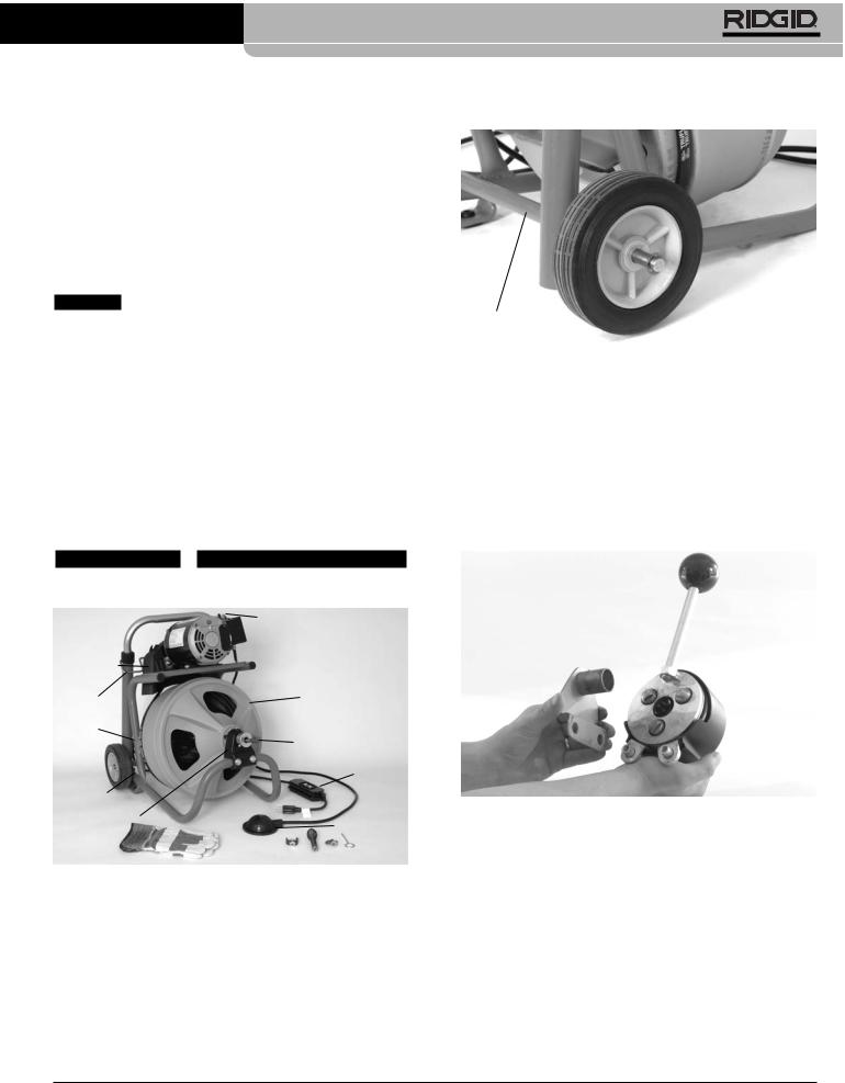
|
FWD/OFF/REV Switch |
Belt Guard |
|
Handle |
Drum |
Adjustment |
|
Manual |
|
Holder |
Cable |
|
|
Handle |
GFCI |
|
|
Bumper |
|
Front Bearing |
Foot Switch |
Mount |
Figure 1 – K-400 Drum Machine with 3/8" Cable and Tools
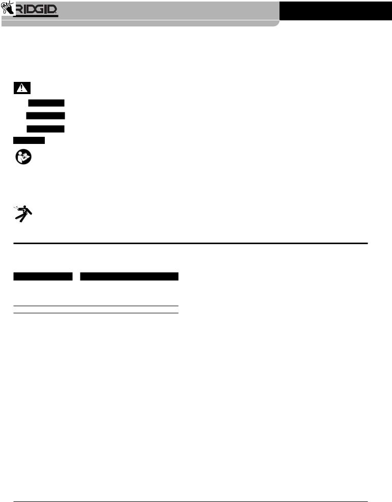
Installing Wheels
1.Install retaining clip into groove on one end of axle.
2.Slide one wheel onto axle with the boss away from the clip.
3.Fully insert axle into axle tube.
4.Slide second wheel onto axle, boss first.
5. Install retaining clip into groove.
Axle Tube
Figure 2 – Assembling Wheel
Mounting AUTOFEED®
(Optional Accessory)
1.Screw handle into the AUTOFEED.
2.Place the mounting bracket onto the back of the AUTOFEED. Bracket shaft must be inserted into the center hole of the AUTOFEED while the two (2) holes in the bracket must be aligned with the mounting pins (Figure 3).
Figure 3 – Placing Mounting Bracket Into AUTOFEED
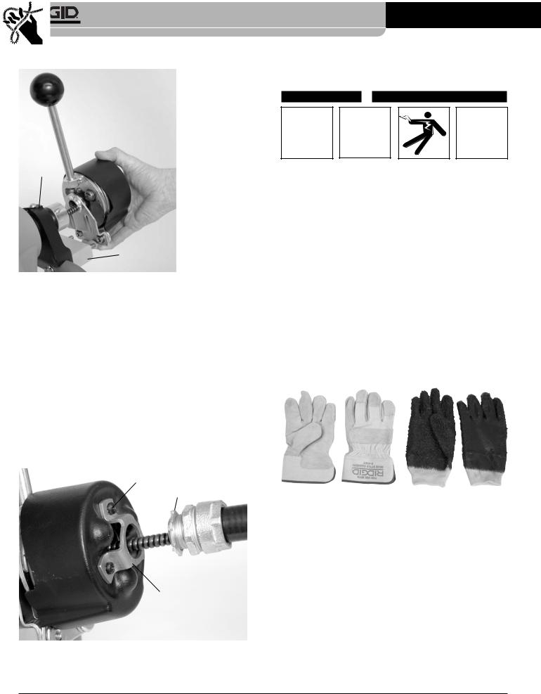
3.Remove the two bolts and nuts holding front bearing mount to frame. Keep bearing mount and drum in place.
4.Attach spacer block and AUTOFEED onto the front frame of the K-400 using the two (2) supplied 5/16" x 3" hex head bolts and lock washers. Insert the bolts into the holes in the frame from the back (Figure 4). Slide the spacer block onto bolts, then attach the AUTOFEED. Be sure to use the lock washers and tighten the bolts until the AUTOFEED is secure. DO NOT OVERTIGHTEN.
Ridge Tool Company |
5 |
K-400 Drain Cleaning Machine
Front
Bearing
Mount
Spacer Block
Figure 4 – Mounting AUTOFEED Onto The Frame
Mounting Guide Hose to AUTOFEED® (Optional Accessory)
1.Remove the three (3) cover screws from the front of the AUTOFEED. Keep AUTOFEED cover in place.
2.Attach the guide hose adapter to front of AUTOFEED using these same screws. DO NOT OVERTIGHTEN.
3.Put the tip of the cable into the coupling end of the guide hose and feed it through the hose until cable tip extends out the opposite end of the hose.
4.Screw the guide hose coupling onto adapter. Position hose so that the natural curve of the hose follows the path to the drain. Tighten lock nut to keep hose from rotating. See Figure 5.
Cover Screw
Lock Nut
Guide Hose Adapter
Figure 5 – Mounting Guide Hose To AUTOFEED
Machine Inspection
 WARNING
Before each use, inspect your drain cleaning machine and correct any problems to reduce the risk of serious injury from electric shock, twisted or broken cables, chemical burns, infections and other causes and prevent drain cleaner damage.
Always wear safety glasses, RIDGID drain cleaning gloves, and other appropriate protective equipment when inspecting your drain cleaner. For extra protection from chemicals and bacteria on the e- quipment, wear latex, rubber or other liquid barrier gloves under the RIDGID drain cleaning gloves.
1.Inspect the RIDGID drain cleaning gloves. Make sure they are in good condition with no holes, tears or loose sections that could be caught in the rotating cable. It is important not to wear improper or damaged gloves. The gloves protect your hands from the rotating cable. If the gloves are not RIDGID drain cleaning gloves or are damaged or worn out, do not use machine until RIDGID drain cleaning gloves are available. See Figure 6.
Figure 6 – RIDGID Drain Cleaning Gloves – Leather, PVC
2.Make sure that the drain cleaning machine is unplugged and inspect the power cord, Ground Fault Circuit Interrupter (GFCI) and plug for damage. If the plug has been modified, is missing the grounding prong or if the cord is damaged, to avoid electrical shock, do not use the machine until the cord has been replaced by a qualified repair person.
3.Clean any oil, grease or dirt from all equipment handles and controls. This helps prevent the machine or control from slipping from your grip.
4.Make sure the foot switch is attached to the drain cleaning machine. Do not operate the machine without the foot switch.
6 |
Ridge Tool Company |

K-400 Drain Cleaning Machine
5.Make sure the machine is properly assembled. Inspect the drain cleaning machine for any broken, worn, missing, mis-aligned or binding parts or any other condition which may prevent safe and normal operation. Make sure that handles move smoothly between positions and lock in place, and that the bumpers at the bottom of the handle are present and firmly attached. Rotate the drum and make sure that it turns freely without binding. If any problems are found, do not use machine until problems have been repaired.
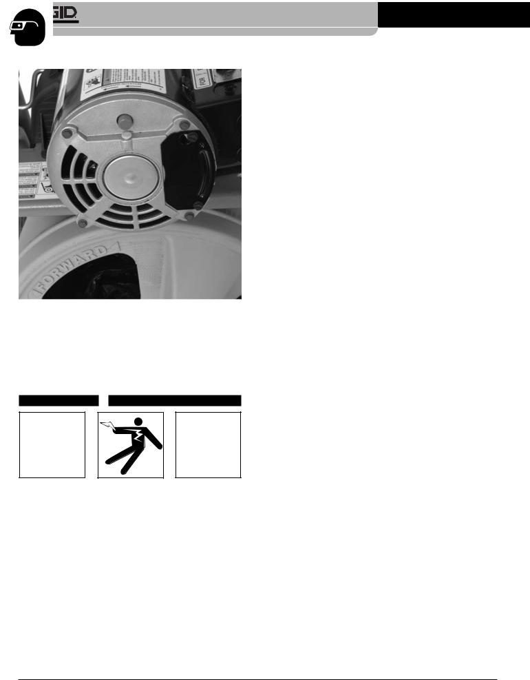
6.Check that the warning label is present, firmly attached and readable. Do not operate the drain cleaning machine without the warning label. See Figure 7.
Figure 7 – Warning Label – Motor
7.Check the belt guard to insure that it is securely fastened to the drain cleaner. Do not operate without guard in place. See Figure 1.
8.Clean any debris from the cable and tools. Inspect cables for wear and damage. Inspect for
•Wear – wear can be identified by looking for flats on the outside of the cable. Cables are made from round wire, and the outside of the cable should be rounded like the wire profile. If you can see an obvious flat on the outside of the cable, it is worn and should be replaced.
•Cable kinks – If the cable is not perfectly straight but is slightly “wavy”, that is acceptable. Kinked cables have a well-defined bend, and may have gaps between the coils of the cable. Slight kinks (up to 15°) can be straightened, but all kinks weaken the cable and can cause cable failure during use. Cables with multiple or excessively large kinks should be replaced.
•Space between cable coils – space between the cable coils indicates that the cable has been deformed. This can be caused by kinking, stretching (mechanically pulling the cable) or running the cable
in REVERSE (REV). Cables with space between the coils should be replaced.
•Excessive corrosion – this can be caused by storing the cable wet or using the cable in corrosive chemicals used in chemical clog removers. Corrosion weakens the cable and can make it brittle. Excessively corroded cable should be replaced.
All of these forms of wear and damage weaken the cable and make cable twisting, kinking or breaking more likely during use. Make sure the cable is fully retracted with no more than 2" of cable outside of the machine. This will prevent whipping of the cable at start up.
9.Inspect the tools for wear and damage. If necessary, replace prior to using the drain cleaning machine. Dull or damaged cutting tools can lead to binding, cable breakage, and slow the drain cleaning process.
10.Make sure that the FOR/OFF/REV switch is set to the OFF position.
11.With dry hands, plug cord into properly grounded outlet. Test the GFCI provided in the electrical cord to insure that it is operating correctly. When the test button is pushed in, the indicator light should go off. Reactivate by pushing the reset button in. If the indicator light goes on, the GFCI is functioning properly. If GFCI is not functioning properly, unplug the cord and do not use the drain cleaning machine until the GFCI has been repaired.
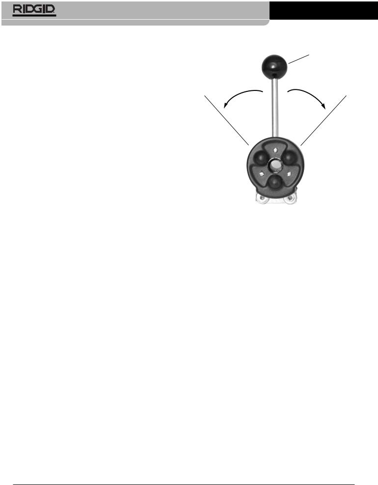
12.Move the FOR/OFF/REV switch into the FOR position. Press the foot switch and note the direction of rotation of the drum. If the foot switch does not control the machine operation, do not use the machine until the foot switch has been repaired. The drum should rotate counter-clockwise when viewed from the front of the drum, and will match the drum direction shown on the warning label and the arrows molded into the drum (Figure 8). Release the foot switch and let the drum come to a complete stop. Place the FOR/OFF/REV switch into the REV position, and repeat above testing to confirm that the drain cleaner operates properly in reverse. If the rotation is not correct, do not use the machine until it has been repaired.
Ridge Tool Company |
7 |
K-400 Drain Cleaning Machine
Figure 8 – Drum Rotation Direction Arrows
13.With the inspection complete, move the FOR/OFF/REV switch into the OFF position and, with dry hands, unplug the machine.
Machine and Work Area Set-Up
 WARNING
Set up the drain cleaning machine and work area according to these procedures to reduce the risk of injury from electric shock, fire, machine tipping, twisted or broken cables, chemical burns, infections and other causes, and prevent drain cleaner damage.
Always wear safety glasses, RIDGID drain cleaning gloves, and other appropriate protective equipment when setting up your drain cleaner. For extra protection from chemicals and bacteria on the machine and in the work area, wear latex, rubber or other liquid barrier gloves under the RIDGID drain cleaning gloves. Rubber soled, non-slip shoes can help prevent slipping and electric shock, especially on wet surfaces.
1.Check work area for:
• Adequate lighting.
•Flammable liquids, vapors or dust that may ignite. If present, do not work in area until sources have been identified and corrected. The drain cleaner is not explosion proof and can cause sparks.
•Clear, level, stable dry place for machine and operator. Do not use the machine while standing in water. If needed, remove the water from the work area.
•Properly grounded electrical outlet. A three-prong or GFCI outlet may not be properly grounded. If in doubt, have outlet inspected by a licensed electrician.
•Clear path to electrical outlet that does not contain any potential sources of damage for the power cord.
•Clear path to transport the drain cleaner to the work area.
2.Inspect the drain to be cleaned. If possible, determine the access point(s) to the drain, the size(s) and length(s) of the drain, distance to tanks or mainlines, the nature of the blockage, presence of drain cleaning chemicals or other chemicals, etc. If chemicals are present in the drain, it is important to understand the specific safety measures required to work around those chemicals. Contact the chemical manufacturer for required information.
If needed, remove fixture (water closet, sink, etc.) to allow access to the drain. Do not feed the cable through a fixture. This could damage the drain cleaner and the fixture.
3.Determine the correct drain cleaning equipment for the application. The K-400 is made for
•11/2" to 3" lines up to 100' long with 3/8" cable
•2" to 4" lines up to 75’ long with 1/2" cable
•The K-400 is not designed to remove root blockages
•Drain cleaners for other applications can be found by consulting the Ridge Tool Catalog, on line at www.RIDGID.com or by calling Ridge Tool Technical Services at 800-519-3456.
4.Make sure machine has been properly inspected.
5.If needed, place protective covers in the work area. The drain cleaning process can be messy.
6.Take the drain cleaning machine to the work area along the clear path. Before moving the machine, make sure that the handle is locked into the upright position for transport. If the machine needs to be lifted, use proper lifting techniques. Use care moving equipment up and down stairs, and be aware of possible slip hazards. Wear appropriate footwear to help prevent slips.
8 |
Ridge Tool Company |
K-400 Drain Cleaning Machine
Figure 9 – Example of Extending Drain to Within 2' of Drain Opening
6.Position the drain cleaning machine so that the drum opening is within 2 feet of the drain access. Greater distances from the drain access increases the risk of the cable twisting or kinking. If the machine cannot be placed with the drum opening within 2’ of the drain access, extend the drain access back to within 2’ of the drum opening with similar sized pipe and fittings. Improper cable support can allow the cable to kink and twist and can damage the cable or injure the operator. (See Figure 9.)
7.Pull the handle locking lever and lower the handle until it locks into the lowest position. Check to make sure that the rubber bumpers on the lower end of the handle are firmly in contact with the floor. This helps stabilize the machine and prevent tipping or walking during use. Do not operate with the handle in any other position.
8.Evaluate the work area and determine if any barriers are needed to keep bystanders away from the drain cleaner and work area. The drain cleaning process can be messy and bystanders can distract the operator.
9.Select proper tool for the conditions.
If the nature of the obstruction is unknown, it is good practice to use a straight or bulb auger to explore the obstruction and retrieve a piece of the obstruction for inspection.
Once the nature of the obstruction is known, an appropriate tool can be selected for the application. A good rule of thumb is to start by running the smallest available tool through the blockage to allow the backed
up water to start flowing and carry away the debris and cuttings as the drain is cleaned. Once the drain is open and flowing, other tools appropriate for the blockage can be used. Generally, the largest tool used should be no bigger than the inside diameter of the drain minus one inch.
Figure 10 – Tools Supplied With K-400
The K-400 is supplied with these tools.
•Cable Pin Key
•The T-202 Bulb Auger – for exploration of the clog and pulling out stoppages such as hair, etc.
•The T-205 “C” Cutter – for use in grease blockages and cleaning the walls of the pipe.
•The T-211 Spade Cutter – for use after an auger and to open up floor drains
Proper tool selection depends on the specific circumstances of each job and is left to the users’ judgement.
A variety of other cable attachments are available and are listed in the Accessories section of this manual. Other information on cable attachments can be found in the RIDGID Catalog and on line at www.RIDGID.com.
10.Install the tool to the end of the cable. The T-slot coupler allows the cutting tool to be snapped into the cable coupler. As the cutting tool is installed make sure that the spring-loaded plunger in the coupling on the end of the cable moves freely to retain the tool. If the pin sticks in the retracted position, the cutting tool may fall off in use. To remove cutting tool, insert the pin key into the hole in the coupling to depress the plunger and slide the coupling apart. (See Figure 11.)
To Couple Cable |
To Uncouple Cable and Tools |
||
and Tools |
|||
|
|
||
Snap Together |
Insert Pin |
Slide Apart |
|
Figure 11 – Coupling and Uncoupling Tools
Ridge Tool Company |
9 |

K-400 Drain Cleaning Machine
11.Position the foot switch for easy accessibility. You must be able to hold and control the cable, control the foot switch, and reach the FOR/OFF/REV switch.
12.Confirm that the FOR/OFF/REV switch is in the OFF position.
13.Run the cord along the clear path. With dry hands plug the drain cleaner into a properly grounded outlet. Keep all connections dry and off the ground. If the power cord is not long enough, use an extension cord that
•Is in good condition
•Has a three prong plug similar to that supplied on the drain cleaner
•Is rated for outdoor use and contains a W or W-A in the cord designation (i.e. SOW).
•Has sufficient wire size (16 AWG for 50’ or less, 14 AWG for 50' – 100' long). Undersized wires can overheat, melting the insulation or causing a fire or other damage.
When using an extension cord, the GFCI on the drain cleaner does not protect the extension cord. If the outlet is not GFCI protected, it is advisable to use a plug in type GFCI between the outlet and the extension cord to reduce the risk of shock if there is a fault in the extension cord.
Operating Instructions
 WARNING
Always wear eye protection to protect your eyes against dirt and other foreign objects.
Only wear RIDGID drain cleaning gloves. Never grasp the rotating cable with anything else, including a glove or a rag. They can become wrapped around the cable, causing serious injury.
When cleaning drains that might contain hazardous chemicals or bacteria, wear appropriate protective equipment, such as goggles, face shields or respirators, to prevent burns and infections. For extra protection from chemicals and bacteria on the machine and in the work area, wear latex, rubber or other liquid barrier gloves under the RIDGID drain cleaning gloves. Rubber soled, non-slip shoes can help prevent slipping and electric shock, especially on wet surfaces.
Follow operating instructions to reduce the risk of injury from twisted or broken cables, cable ends whipping around, machine tipping, chemical burns, infections and other causes.
1.Make sure that the machine and work area have been properly set up and the work area is free of bystanders and other distractions.
2.Pull cable out of drum and feed into drain. Push cable as far into drain as it will go. At least one foot of cable must be in drain so that the end of the cable will not come out of the drain and whip around when you start the machine.
3.Assume a proper operating position.
•Be sure you can control the ON/OFF action of the foot switch and can quickly release the foot switch if needed. Do not step on foot switch yet.
•Be sure that you have good balance, do not have to over reach, and cannot fall on the foot switch, drain cleaning machine, the drain or other hazards.
•You must be able to place at least one hand on the cable at all times to control and support the cable as it feeds into the drain and blockage.
•You must be able to reach the FOR/OFF/REV switch.
This operating position will help to maintain control of the cable and machine. (See Figure 12.)
Figure 12 – In Operating Position, Manually Feeding Cable
4.Move the FOR/OFF/REV switch to the FOR (FORWARD) position. Do not depress the foot switch yet. FOR/OFF/REV refers to the cable rotation and not to the direction of cable movement. Do not rotate the cable in reverse except as specifically described in these instructions. Running the drain cleaner in REV can damage the cable.
10 |
Ridge Tool Company |

K-400 Drain Cleaning Machine
Using Manual Feed Machine
Grasp the cable with both gloved hands and pull a short section (6" - 12") of cable from the drum so that there is a slight bow in the cable. Gloved hands must be on the cable to control and support the cable. Improper cable support can allow the cable to kink or twist and can damage the cable or injure the operator. (See Figure 12.)
Starting the cable in the drain
Confirm at least one foot of cable is in the drain. Press the foot switch to start the machine. Feed the rotating cable into the drain. The rotating cable will slowly work its way into the drain as you push on the cable with gloved hands.
The person controlling the cable must also control the foot switch. Do not operate the drain cleaner with one person controlling the cable and another person controlling the foot switch. This can lead to kinking, twisting and breaking of the cable. Twisting, kinking or breaking cables can cause striking or crushing injuries.
If it is hard to get the cable through a trap, the following methods or combination of methods can be used.
•First, sharp downward thrusts on the cable, both with and without the cable turning, can help to get the tool to pass through the trap.
•A second method is to run the drain cleaner in REV (REVERSE) for several seconds while pushing on the cable. Only do this long enough to get the cable started through the trap. Running the drain cleaner in reverse can damage the cable.
•A third method is to attach a single section (only one section) of C-9 cable between the end of the cable and the tool.
•Finally, if none of these options work, consider using a smaller diameter or more flexible cable, or a different drain cleaner.
Cleaning the drain
With the cable rotating in FORWARD (FOR) direction pull short sections (6" - 12") of cable out of the drum and feed it into the drain. Always keep both hands on the cable. As you feed the cable into the drain, you may feel and see the cable slow down and feel the cable start to wind or load up (this will feel like the cable is starting to twist or squirm). This may be a transition in the drain line (trap, elbow, etc.) or build up in the drain (mud, grease, etc.) or the actual blockage. Feed the cable slowly and carefully. Do not let cable build up outside the drain. This can cause the cable to twist, kink or break.
Pay attention to the amount of cable that has been fed into the drain. Feeding cable into a larger sewer main, septic tank, or similar transition may cause the cable to kink or
knot and prevent removal from the drain. Minimize the amount of cable fed into the transition to prevent problems.
Working the blockage
If the tool at the end of the cable stops turning, it is no longer cleaning the drain. If the tool becomes lodged in the blockage and power is maintained to the drain cleaner, the cable will start to wind up (this will feel like the cable is starting to twist or squirm). Having both hands on the cable allows you to feel this wind up and control the cable. As you feel the cable wind up, or if the tool stops turning, pull back on the cable to free the tool from the blockage. Don’t keep the cable rotating if the tool is stuck in a blockage. If the tool stops turning and the drum keeps rotating, the cable can twist, kink or break.
Once the tool is free of the blockage and is turning again, you can slowly feed the rotating cutting tool back into the blockage. Do not try to force the tool through the blockage. Let the spinning tool “dwell” in the blockage to help completely break it up. Work the tool in this manner until it has moved completely past the blockage (or blockages), and the drain is flowing.
While working the blockage, the tool and cable may become clogged with debris and cuttings from the blockage. This can prevent further progress. The cable and tool need to be retrieved from the drain and the debris removed. See section on “Retrieving the Cable”.
Handling a stuck tool
If the tool stops turning and the cable cannot be pulled back from the blockage, release the foot switch while firmly holding the cable with both hands. Do not remove hands from cable or cable may kink, twist and break. The motor will stop and the cable and drum will turn backwards until the energy stored in the cable is relieved. Do not remove hands from cable until the tension is released. Place FOR/OFF/REV switch in OFF position.
The torque limiter helps to prevent cable damage from cable flip over in the drum by stopping drum and cable rotation when the torque exceeds a certain value. The motor will continue to rotate as long as the foot switch is pressed, but the drum and cable will stop rotating when the torque limiter setting is exceeded. The torque limiter cannot prevent all cable damage in the drum, and cannot prevent cable flip over outside the drum. If the drum stops turning, the cable and tool also are not turning.
Freeing a stuck tool
If the tool is stuck in the blockage, with the FOR/OFF/- REV switch in the OFF position and the foot switch released, try pulling the cable loose from the blockage. If the tool will not come free from the blockage, place the FOR/OFF/REV switch in the REV position. Grasp the
Ridge Tool Company |
11 |
K-400 Drain Cleaning Machine
cable with both gloved hands, press the foot switch for several seconds and pull on the cable until it is free of the blockage. Do not operate the machine in the REV position any longer than required to free the cutting tool from the blockage or cable damage can occur. Place the FOR/OFF/REV switch in the FOR position and continue cleaning the drain.
Retrieving the cable
Once the drain is open, start a flow of water down the drain to flush the debris out of the line. This can be done by running a hose down the drain opening, turning on a faucet in the system or other methods. Pay attention to the water level, as the drain could plug again.
With water flowing through the drain, retrieve the cable from the line. The FOR/OFF/REV switch should be in the FOR position – do not retrieve the cable with the FOR/OFF/REV in the REV position, this can damage the cable. As with feeding the cable into the drain, keep both hands on the cable for control. The tool can become caught while being retrieved. Pull 6" - 12" of cable from the drain at a time and feed back into the drum. The flow of water down the line will help to clean the cable as it is retrieved. Continue retrieving the cable this way until the tool is just inside the drain opening. Release your foot from the foot switch, allowing the drum to come to a complete stop. Do not pull the end of the cable from the drain while the cable is rotating. The cable can whip around and could cause serious injury.
Place the FOR/OFF/REV in the OFF position and with dry hands unplug the machine. Pull the remaining cable from the drain by hand and feed into the drain cleaner. If needed, change the tool and continue cleaning following the above process. Several passes through a line are recommended for complete cleaning.
Using Machines with AUTOFEED
Grasp the cable with a gloved hand. Gloved hand must be on the cable to control and support the cable. Improper cable support can allow the cable to kink and twist and can damage the cable or injure the operator. Place your other hand on the feed lever. Feed lever should be in the neutral position (vertical or straight up). (See Figure 13.)
Neutral
Feed Lever
Advance |
Retrieve |
Figure 13 – AUTOFEED Directions (Viewed From Front
of Machine)
Starting the cable in the drain
Confirm at least one foot of cable is in drain. Press on the foot switch to start the machine. To advance the cable into the drain, move the feed lever in the same direction as the drum and cable rotation. Move the feed lever away from the neutral (vertical) position until it engages and advances the cable. Advance (or retrieve) can be almost 90 degrees from the neutral position. The rotating cable will work its way into the drain. The person controlling the cable and the power feed must also control the foot switch. Do not operate the drain cleaner with one person controlling the cable and power feed and another person controlling the foot switch. This can lead to kinking, twisting and breaking of the cable. Twisting, kinking or breaking cables can cause striking or crushing injuries.
If it is hard to get the cable through a trap, the following methods or combination of methods can be used.
•First, sharp downward thrusts on the cable, both with and without the cable turning, can help to get the tool to pass through the trap.
•A second method is to run the drain cleaner in REV (REVERSE) for several seconds while pushing down on the cable. Only do this long enough to get the cable started through the trap. Running the drain cleaner in reverse can damage the cable.
•A third method is to attach a single section (only one section) of C-9 cable between the end of the cable and the tool.
12 |
Ridge Tool Company |
K-400 Drain Cleaning Machine
•Finally, if none of these options work, consider using a smaller diameter or more flexible cable, or a different drain cleaner.
Figure 14 – AUTOFEED in Retrieve Position
Cleaning the drain
Always keep one hand on the cable. As you feed the cable into the drain, you may feel and see the cable slow down and feel the cable start to load or wind up (this will feel like the cable is starting to twist or squirm). This may be a transition in the drain line (trap, elbow, etc.) or build up in the drain (mud, grease, etc.), the actual blockage. Feed the cable slowly and carefully. Do not let cable build up outside drain. This can cause the cable to twist, kink or break.
Pay attention to the amount of cable that has been fed into the drain. Feeding cable into a larger sewer main, septic tank, or similar transition may cause the cable to kink or knot and prevent removal from the drain. Minimize the amount of cable fed into the transition to prevent problems.
Working the blockage
If the tool at the end of the cable stops turning, it is no longer cleaning the drain. If the tool becomes lodged in the blockage and power is maintained to the drain cleaner, the cable will start to wind up (this will feel like the cable is starting to twist or squirm) and buildup outside the drain. Having a hand on the cable allows you to feel this wind up and control the cable. As you feel the cable wind up or if the tool stops turning, immediately move the feed lever to the full retrieve position (opposite of cable and drum rotation - See Figure 14) to free the tool from the blockage. Don’t keep the cable rotating if the tool is stuck in a blockage. If the tool stops turning and the drum keeps rotating, the cable can twist, kink or break.
Once the tool is free of the blockage and the tool is turning again, you can slowly feed the rotating tool back into the blockage. Let the spinning tool “dwell” in the blockage to help completely break it up. Do not try to force the
tool through the blockage. Work the tool in this manner until the tool has moved completely past the blockage (or blockages), and the drain is flowing.
While working the blockage, the tool and cable may become clogged with debris and cuttings from the blockage. This can prevent further progress. The cable and tool need to be retrieved from the drain and the debris removed. See section on “Retrieving the Cable”.
If the tool continues to get hung up in the blockage, stop using the auto feed (leave the feed lever in the neutral position) and work the cable by hand as detailed in the Manual Feed Section.
Handling a stuck tool
If the tool stops turning and the cable cannot be pulled back from the blockage, release the foot switch, maintain a firm grip on the cable and move the feed lever to the neutral (straight up) position. Do not remove your hand from cable or the cable may kink, twist and break. The motor will stop and the cable and drum will turn backwards until the energy stored in the cable is relieved. Do not remove hand from the cable until the tension is released. Place FOR/OFF/REV switch in the OFF position.
The torque limiter helps to prevent cable damage from cable flip over in the drum by stopping drum and cable rotation when the torque exceeds a certain value. The motor will continue to rotate as long as the foot switch is pressed, but the drum and cable will stop rotating when the torque limiter setting is exceeded. The torque limiter cannot prevent all cable damage in the drum, and cannot prevent cable flip over outside the drum. If drum stops turning, the cable and tool also are not turning.
Freeing a stuck tool
If the tool is stuck in the blockage, with the FOR/OFF/REV switch in the OFF position and the foot switch released, try pulling the cable loose from the blockage. If the tool will not come free from the blockage, place the FOR/OFF/REV switch in the REV position. With the AUTOFEED in the neutral (straight up) position, Grasp the cable with both gloved hands, press the foot switch for several seconds and pull on the cable until it is free of the blockage. Do not operate the machine in the REV position any longer than required to free the cutting tool from the blockage or cable damage can occur. Place the FOR/OFF/REV switch in the FOR position and continue cleaning the drain.
Retrieving the cable
Once the drain is open, start a flow of water down the drain to flush the debris out of the line. This can be done by running a hose down the drain opening, turning on a faucet in the system or other methods. Pay attention to the water level, as the drain could plug again.
Ridge Tool Company |
13 |

K-400 Drain Cleaning Machine
With water flowing through the drain, retrieve the cable from the line by moving the feed lever in the opposite direction that the cable and drum rotate. The FOR/OFF/REV switch should be in the FOR position – do not retrieve the cable with the FOR/OFF/REV in the REV position, this can damage the cable. As with feeding the cable into the drain, keep one hand firmly on the cable for control. The tool can become caught while being retrieved. The flow of water down the line will help to clean the cable as it is retrieved. Continue retrieving the cable until the tool is just inside the drain opening. Move the feed lever to the neutral position and release the foot switch, allowing the drum to come to a complete stop. Do not pull the end of the cable from the drain while the cable is rotating. The tool can whip around and could cause serious injury.
Place the FOR/OFF/REV in the OFF position and with dry hands unplug the machine. Pull the remaining cable from the drain by hand and feed into the drain cleaner. If needed, change the tool and continue cleaning following the above process. Several passes through a line are recommended for complete cleaning.
Using Machine with an AUTOFEED and a Front Guide Hose
The front guide hose is an accessory to help protect fixtures and contain the liquid and debris thrown off of the cable as it is retrieved from the drain. It can only be used with an AUTOFEED.
Using a machine with the front guide hose is similar to using a machine with just the AUTOFEED. Follow instructions for AUTOFEED operation with the following exceptions: When setting up the machine insert the guide hose at least 6" into the drain. Instead of holding the cable, hold the guide hose. (See Figure 15.) Always control the guide hose and properly support the cable to prevent the cable from twisting, kinking or breaking.
Figure 15 – Using Machine with Guide Hose
When using a front guide hose, pay attention how the guide hose feels in your hand and to watch the drum rotation. Because the guide hose is over the cable, there is less sensitivity to the loading of the cable, and it is harder to tell if the tool is rotating or not. If the tool is not rotating, the drain is not being cleaned.
If the tool continues to get hung up in the blockage, stop using the AUTOFEED (leave the feed lever in the neutral position) and work the cable by hand as detailed in the Manual Feed section. To do this, the cable must be retrieved from the drain and the guide hose removed to allow proper positioning of the machine to the drain and access to the cable. Do not try to work the cable by hand with the front guide hose in place.
Maintenance Instructions
 WARNING
FOR/OFF/REV switch should be OFF and machine unplugged before performing any maintenance.
Always wear safety glasses and RIDGID drain cleaning gloves when performing any maintenance.
Cables
Cables should be thoroughly flushed with water after every use to prevent damaging effects of sediment and drain cleaning compounds. Flush cable with water and drain debris from drum by tipping machine forward after every use to remove sediment, etc. which can corrode cable.
To help prevent corrosion during storage, cables can be
14 |
Ridge Tool Company |

K-400 Drain Cleaning Machine
coated with RIDGID Cable Rust Inhibitor. Once the cable is clean and dry, pull the cable from the drum. While manually feeding the cable back into the drum, wipe the Cable Rust Inhibitor on the cable with a cloth.
Do not apply the Cable Rust Inhibitor to a rotating cable. The cloth and your hand can become entangled in the cable, and Cable Rust Inhibitor can be slung from rotating cable.
AUTOFEED
After each use, hose out AUTOFEED assembly with water and lubricate with lightweight machine oil.
Cleaning
The machine should be cleaned as needed with hot, soapy water and/or disinfectants. Do not allow water to enter motor or other electrical components. Make sure unit is completely dry before plugging in and using.
Lubrication
Lubricate motor as per instructions on motor.
In general, the drain cleaner will not require lubrication. If the drum is removed or changed, grease the bearings with good general purpose grease.
Belt Removal/Installation
1.Remove belt guard by removing hold down screws located next to motor. Do not operate drain cleaner with belt guard removed.
2.Hold the belt tensioner to the side and remove the belt from the drum and pulley. (See Figure 16.) Slide the belt to the front of the machine near the front bearing mount.
3.Remove the two screws and nuts holding the front bearing mount in place. Pull the drum and front bearing mount forward enough to slide the belt off the machine, between the front bearing mount and the frame.
4.Reverse procedure to replace belt. If changing belt, adjust torque limiter as described below.
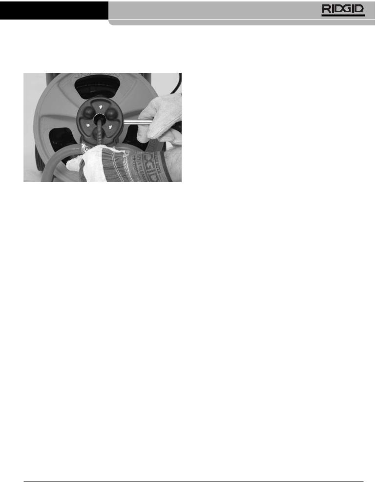
Torque Limiter Adjustment
The K-400 Drain Cleaner is equipped with a torque limiter to help prevent cable damage from flip over in the drum. The torque limiter causes the belt to slip when the torque exceeds a set value. The torque limiter is set at the factory, and in most cases will never need to be adjusted. If excessive belt slippage is experienced during use, this procedure can be used to check and adjust the torque limiter setting. Additionally, if the belt is changed, the torque limiter will need to be checked and adjusted.
NOTICE Do not adjust the torque limiter outside of the specified range. Setting the torque limiter outside of the specified range could result in damage to the machine and cable.
1.Remove belt guard by removing hold down screws located next to motor. Do not operate drain cleaner with belt guard removed.
2.Check the gap between the torque limiter spring coils near the middle of the spring. (See Figure 16.) This can be measured with a set of feeler gauges. The torque limiter is properly set if the gap is 0.048" (1.22 mm) to 0.060" (1.52 mm), about the thickness of a U.S. dime. If the gap is within this range, the torque limiter is properly set and no adjustment is necessary.
3.If torque limiter is outside of acceptable range, the torque limiter must be adjusted.
4.Loosen screw located in the center of hex knob approximately 3 turns.
5.Pull the hex knob out slightly. If the gap needs to be increased, rotate the knob clockwise to the next flat of the hex knob. If the gap needs to be decreased, rotate counter-clockwise to the next flat of the hex knob.
6.Repeat steps 2-5 until the spring coil gap is correct.
7.Tighten the hex knob screw.
8.Reverse procedure to replace the guard.
Belt
Tensioner
Gap
 Hex Knob
Figure 16 – Torque Limiter Adjustment. (Shown With Belt Guard Removed)
Installing Replacement Cable
To Remove Cable From Drum
1.Pull out excess cable from drum allowing access to cable bracket.
2.Loosen screws on back of drum that fasten cable clamps and back plate against back wall of drum.
Ridge Tool Company |
15 |
K-400 Drain Cleaning Machine
3. Pull end of old cable from drum and discard.
To Install Replacement Cable
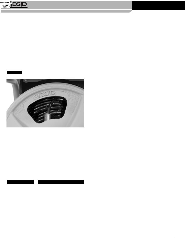
1.To make cable installation easier, completely uncoil new cable before proceeding. Use caution when removing the cable from the package. The cable is under tension and could strike the user. Adding a 30 degree bend about 4 inches from the drum end of cable will facilitate it entering the drum.
2.Insert about 24 inches of cable through the guide tube into the drum.
NOTICE Cable should coil into the drum in a counterclockwise direction (Figure 17).
Figure 17 – Coil Cable Into Drum As Shown
3.Reach inside the drum and maneuver end of cable so that it is between the cable clamp and back plate. The end of the cable should extend at least 3" past the clamp.
4.Retighten the screws to clamp the cable against the back plate and back wall of the drum.
5.Feed cable into drum.
Accessories
 WARNING
Only the following RIDGID products have been designed to function with the K-400 Drain Cleaning Machine. Other accessories suitable for use with other tools may become hazardous when used on the K-400. To prevent serious injury, use only the accessories specifically designed and recommended for use with the K-400, such as those that follow.
IW (Integral Wound) Solid Core Cables
|
|
|
|
Catalog |
Model |
|
|
|
|
Weight |
|
|
|
|
|
No. |
No. |
Description |
|
|
|
lb. |
kg |
" 10mm |
|
|
|
87577 |
C-31IW |
50' (15m) IW Cable |
18 |
8.2 |
|||
|
|
|
|||||||||
|
|
|
87582 |
C-32IW |
75' (23m) IW Cable |
26 |
11.8 |
||||
|
|
|
87587 |
C-33IW |
100' (30m) IW Cable |
34 |
15.4 |
||||
/8 |
|
|
|
91037 |
— |
Repair End for IW Cable |
0.5 |
0.2 |
|||
|
|
|
|||||||||
3 |
|
|
|
||||||||
|
|
|
|
||||||||
12mm |
|
|
|
87592 |
C-44IW |
50' (15m) IW Cable |
27 |
12.2 |
|||
|
|
|
87597 |
C-45IW |
75' (23m) IW Cable |
39 |
17.7 |
||||
/2" |
|
|
|
|
|
|
1 |
2 |
|
|
|
1 |
|
|
|
91042 |
— |
Repair End for |
|
/ |
" IW Cable |
0.6 |
0.3 |
Tools – Fits C-31IW, C-32IW, C-33IW, C-44IW and C-45IW
|
Catalog |
Model |
|
|
|
Replacement |
|
No. |
No. |
Description |
|
|
Blade(s) |
|
62990 |
T-201 |
Straight Auger, 5" Long |
— |
||
|
||||||
|
62995 |
T-202 |
Bulb Auger, 11/8" O.D. |
— |
||
|
||||||
|
63000 |
T-203 |
Bulb Auger |
7 |
8 |
— |
|
|
/ " O.D. |
||||
|
63065 |
T-217 |
Drop Head, 4" Long |
— |
||
|
|
|
|
|
||
|
63005 |
T-205 |
“C” Cutter 13/8" |
97835 |
||
|
|
|
|
|
||
|
63010 |
T-206 |
Funnel Auger, 3" Long |
— |
||
|
|
|
|
|
||
|
63015 |
T-207 |
Spiral Cutter, 11/4" |
97840 |
||
|
63020 |
T-208 |
Spiral Cutter, 11/2" |
97895 |
||
|
63025 |
T-209 |
Spiral Cutter, 2" |
97900 |
||
|
63030 |
T-210 |
Spade Cutter, 1" |
97905 |
||
|
63035 |
T-211 |
Spade Cutter, 13/8" |
97825 |
||
|
63040 |
T-212 |
Spade Cutter, 13/4" |
92850 |
||
|
63045 |
T-213 |
4-Blade Cutter, 1" |
97795 |
||
|
63050 |
T-214 |
4-Blade Cutter, 13/8" |
97910 |
||
|
63055 |
T-215 |
4-Blade Cutter, 13/4" |
97915 |
||
|
63060 |
T-216 |
Chain Knocker, 2" |
98000 |
||
|
|
|
|
|
||
|
49002 |
T-260 |
Tool Set (3/8"- K-400) |
— |
||
|
|
|
– T-202 Bulb Auger |
|
||
|
|
|
– T-205 “C” Cutter |
|
||
|
|
|
– T-211 Spade Cutter |
|
||
|
|
|
– A-13 Pin Key |
|
||
|
12128 |
T-240 |
Tool Set (3/8"- K-400) |
— |
||
|
|
|
– T-202 Bulb Auger |
|
||
|
|
|
– T-211 Spade Cutter |
|
||
|
|
|
– A-13 Pin Key |
|
||
|
|
|
|
|
|
|
Accessories
|
|
|
|
|
Catalog |
Model |
|
|
|
|
|
|
|
|
Weight |
|
|
|
|
|
|
No. |
No. |
Description |
lb. |
kg |
|||||||
|
|
|
|
|
41937 |
— |
RIDGID Drain Cleaning |
1/2 |
0.2 |
|||||||
|
|
|
|
|
||||||||||||
|
|
|
|
|
|
|
Gloves, Leather |
|
|
|
||||||
|
|
|
|
|
70032 |
— |
RIDGID Drain Cleaning |
|
|
|
||||||
|
|
|
|
|
|
|
Gloves, PVC |
|
|
|
||||||
|
|
|
|
|
|
|
|
|
|
|||||||
|
|
|
|
|
59230 |
A-13 |
Pin Key For 3/8" Cable |
— |
— |
|||||||
|
|
|
|
|
59225 |
A-12 |
Pin Key For 1/2" Cable |
|
|
|
||||||
|
|
|
|
|
|
|
|
|
|
|
|
|
|
|
|
|
|
|
|
|
|
26773 |
— |
K-400 AUTOFEED Assembly |
2 |
0.9 |
|||||||
|
|
|
|
|
||||||||||||
|
|
|
|
|
|
|
|
|
|
|||||||
|
|
|
|
|
27048 |
— |
K-400 Drum Assembly |
10 |
4.5 |
|||||||
|
|
|
|
|
92607 |
— |
3 |
8 |
" x |
1 |
2 |
" Tool Adapter |
1 |
2 |
0.2 |
|
|
|
|
|
|
|
/ |
|
/ |
|
/ |
||||||
|
|
|
|
|
92682 |
— |
3 |
8 |
" x |
1 |
2 |
" Drop Head Adapter |
1 |
2 |
0.2 |
|
|
|
|
|
|
|
/ |
|
/ |
|
/ |
||||||
|
|
|
|
|
92687 |
— |
|
|
|
|
|
1 |
2 |
1 |
2 |
0.2 |
|
|
|
|
|
Coupling / " Drop Head Tool |
|
/ |
|||||||||
|
|
|
|
|
26778 |
— |
Guide Hose |
2 |
1 |
|||||||
|
|
|
|
|
51317 |
C-9 |
Trap Leader |
5 |
2.2 |
|||||||
|
|
|
|
|
59982 |
— |
Cable Rust Inhibitor 1qt. |
21/2 |
1.2 |
|||||||
|
|
|
|
|
59987 |
— |
Cable Rust Inhibitor 1gal. |
81/2 |
3.8 |
|||||||
16 |
Ridge Tool Company |

K-400 Drain Cleaning Machine
Machine Storage
 WARNING The drain cleaner and cables must be kept indoors or well covered in rainy weather. Store the machine in a locked area that is out of reach of children and people unfamiliar with drain cleaners. This machine can cause serious injury in the hands of untrained users.
Service and Repair
 WARNING
Improper service or repair can make machine unsafe to operate.
The “Maintenance Instructions” will take care of most of the service needs of this machine. Any problems not addressed by this section should only be handled by an authorized RIDGID service technician.
Chart 1 Troubleshooting
Tool should be taken to a RIDGID Independent Authorized Service Center or returned to the factory.
When servicing this machine, only identical replacement parts should be used. Use of other parts may create a risk of electrical shock or other serious injury.
If you have any questions regarding the service or repair of this machine, call or write to:
Ridge Tool Company
Technical Service Department
400 Clark Street
Elyria, Ohio 44036-2023
Tel: (800) 519-3456
E-mail: TechServices@ridgid.com
For name and address of your nearest Independent Authorized Service Center, contact the Ridge Tool Company at (800) 519-3456 or http://www.RIDGID.com
PROBLEM |
|
POSSIBLE REASONS |
|
SOLUTION |
|
||
|
|
|
|
|
|||
Cable kinking or breaking. |
|
Cable is being forced. |
Do Not Force Cable! Let the cutter do the work. |
|
|||
|
|
|
Cable used in incorrect pipe diameter. |
Use 1/2″ cables in 3″ to 4″ lines. |
|
||
|
|
|
Motor switched to reverse. |
Use reverse only if cable gets caught in pipe. |
|
||
|
|
|
Cable exposed to acid. |
Clean and oil cables routinely. |
|
||
|
|
|
Cable worn out. |
If cable is worn, replace it. |
|
||
|
|
|
Cable not properly supported. |
Support cable properly, see instructions. |
|
||
|
|
|
Torque limiter not properly adjusted. |
|
Properly adjust torque limiter. |
|
|
|
|
|
|
|
|
|
|
Drum stops while foot |
|
Hole in foot switch or hose. |
Replace damaged component. |
|
|||
switch is depressed. |
|
Hole in diaphragm switch. |
If no problem found with pedal or hose, replace |
|
|||
Restarts when foot |
|
|
|||||
|
|
|
diaphragm switch. |
|
|||
switch is re-depressed. |
|
|
|
|
|
||
|
|
|
|
|
|
||
Drum turns in one direc- |
|
Faulty reverse switch. |
Replace switch. |
|
|||
tion but not the other. |
|
|
|
|
|
|
|
Ground Fault Circuit Inter- |
|
Damaged power cord. |
Replace cord set. |
|
|||
rupter trips when machine |
|
Short circuit in motor. |
Take motor to authorized service center. |
|
|||
is plugged in or when foot |
|
|
|||||
|
Faulty Ground Fault Circuit Interrupter. |
Replace cord set that includes a Ground Fault |
|
||||
pedal is depressed. |
|
|
|||||
|
|
|
|
|
Circuit Interrupter. |
|
|
|
|
|
Moisture in motor, switch box or on plug. |
|
Take drain cleaner to an Authorized Service Center. |
|
|
|
|
|
|
|
|
|
|
Motor turning but drum |
|
Torque limiter slipping because improperly adjusted. |
Properly adjust torque limiter. |
|
|||
is not. |
|
Torque limiter slipping because cable is being forced. |
Do not force cable. |
|
|||
|
|
|
|
||||
|
|
|
Belt not on drum or pulley. |
Re-install belt. |
|
||
|
|
|
|
|
|
|
|
Ridge Tool Company |
17 |

K-400 Drain Cleaning Machine
Chart 1 Troubleshooting
PROBLEM |
|
|
POSSIBLE REASONS |
|
|
SOLUTION |
|
|
|
|
|
|
|
|
|
AUTOFEED doesn’t work. |
|
|
AUTOFEED full of debris. |
|
Clean AUTOFEED. |
|
|
|
|
|
AUTOFEED needs lubrication. |
|
Lubricate AUTOFEED. |
|
|
|
|
|
|
|
|
|
|
Machine wobbles or |
|
|
Cable not evenly distributed. |
|
Pull all cable out and refeed in, evenly distribute. |
|
|
moves while cleaning |
|
|
Bumpers on handle are not on ground. |
|
Lower handle completely. |
|
|
drain. |
|
|
|
|
|||
|
|
Ground not level. |
|
Place on level stable surface. |
|
||
|
|
|
|
|
|||
|
|
|
|
|
|
|
|
Wiring Diagram
115V
18 |
Ridge Tool Company |
 Loading...