


3801 (E)
3802 (E)
3811 (E)
3812 (E)
3813 (E)
3814 (E)
GB |
p. |
1 |
DE |
p. |
6 |
FR |
p. 11 |
|
NL |
p. 17 |
|
IT |
p. 22 |
|
ES |
p. 27 |
|
PT |
p. 32 |
|
SV |
p. 38 |
|
DA |
p. 43 |
|
NO |
p. 48 |
|
FI |
p. 53 |
|
HR |
p. 58 |
|
PL |
p. 63 |
|
RO |
p. 68 |
|
CZ |
p. 73 |
|
HU |
p. 78 |
|
GR |
p. 84 |
|
RU |
p. 90 |
|
RIDGE TOOL COMPANY

3801(E), 3802(E), 3811(E), 3812(E), 3813(E), 3814(E)
GB
3801(E), 3802(E), 3811(E), 3812(E), 3813(E), 3814(E)
Operating Instructions
WARNING! Read these instructions and the accompanying safety booklet carefully before using this equipment. If
you are uncertain about any aspect of using this tool, contact your RIDGID distributor for more information.
Failure to understand and follow all instructions may result in electric shock, fire, and/or serious personal injury.
SAVE THESE INSTRUCTIONS!
Assembling
1.a. 1 1/4”, 2” and 3” machines.
Place the bending frame with its supports on the floor and slip the ring over the front of the pump cylinder.
Place the U-bracket through the holes in the ring block of the bending
frame. The pump cylinder and pipe bending frame are now fixed in the correct position.
1.b. 4” machine.
-Place the base beam on the floor.
-Place the lower wing on the base beam.
-Place the bending-pump on the base beam, hook the lower wing into the pump and secure the pump at the rear with two M10 bolts.
-Place the corner-supports and where applicable the bendingformer that you will be using, on the lower wing.
-Place the upper wing on the corner-supports and hook it into the pump.
-Insert the fixing-pins through the wings and the corner-supports.
ASSEMBLING OF THE 4” MACHINE
Upper
Corner with fi
Lower
2.Mount a bending former according to the diameter of the pipe to be bent, on the ram top. The corner supports must be placed between, or on the bending frame. They are fastened by means of the fixing-pins. The holes in the frame allow the corner supports to be adjusted to the desired outside diameters. The holes are marked accordingly. Ensure that the fixing pins for corner supports are properly fitted through both wings or through the bending frame to prevent damage.
Bending
1.The filling cap is pierced for air release. Whenever the bending machine is transported this filling cap must be tightly closed, but released a little when in use.
2.Before bending, the pipe should be slightly greased. The pipe is then slipped between the corner supports and bending former. The relief spindle must be locked tightly. By moving the handle up and down the pump is put into operation. The ram moves out and the pipe is bent. The bending operation should be continued until the desired curve
is reached but not further than the bending former curve. It should be remembered that the pipe will spring back a little according to the quality of the pipe. This must be established by experience.
3.As soon as the pipe reaches its required shape, loosen the relief spindle and the ram withdraws automatically. Disconnect one of the corner supports and the pipe can be removed. The models equipped with an open frame have the advantage that the bent tube can removed easier, especially long pieces of tubes with several bends, thus saving a lot of time.
4.If a bend has been bent too far this can be corrected by means of the straightener. The ram must be reversed and the tube turned over
against the corner supports. The straightener is placed on the ram top and the bend can now be pushed back to its desired shape. On the
1 1/4” bending machine a bend of 90° cannot normally be corrected. This also applies to the 3” machine for 2 1/2” and 3”, for the 4” machine for 3” and 4” pipes.
5.For 3” and 4” model only.
When bending 2 1/2”, 3” and 4” pipes an extension piston should be applied to the ram when the tube has been bent past 75°. The stroke of the ram is not enough to bend a 90° bend in one operation.
6.1 1/4”, 2”, 3”, 4” electro-hydraulic pipe bending machines.
The electro-hydraulic pipe bending machines are equipped with a single phase 115 V, 220 V, AC or 380 V 3 phase motor. The motor has a special safety switch. Once the motor is running the movement of the ram is controlled by means of a relief spindle which can be either opened or closed. The motor does not have to be switched off. The machine also features a pressure safety valve. This is factory set so that heavy wall pipe (steam pipe) can be bent without any problem. The pressure safety valve is situated in the pump housing and can only be set by means of a manometer.
Bending of Hairpin Shapes of 180°
For this, additional accessories are required which can be delivered on request.
Assembling
1.See under assembling bending machine.
2.The bending former (180°) according to the size of the pipe to be bent, is placed on the ram. Next, the plates (spare frames) with 3 rolls (diabolos) are adjusted between or in the frame. The fixing-pins for corner supports must be put in the holes 1 1/4” through the center lock; the removable diabolo must be removed and the pipe to be bent run through. The pipe must now touch the center diabolo with one side and the 180° bending form with the other side. Bending can now be started.
Bending
1.See under bending.
2.If the bending is more than 90°, the ram must be reversed, by releasing the relief spindle. Adjust the removable diabolos and bend up to 180°. To remove the bent pipe, see Bending.
Ridge Tool Company |
1 |

3801(E), 3802(E), 3811(E), 3812(E), 3813(E), 3814(E)
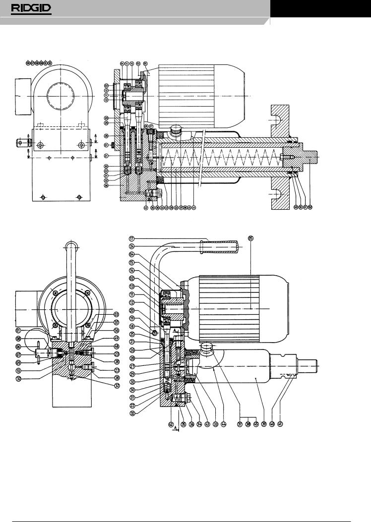
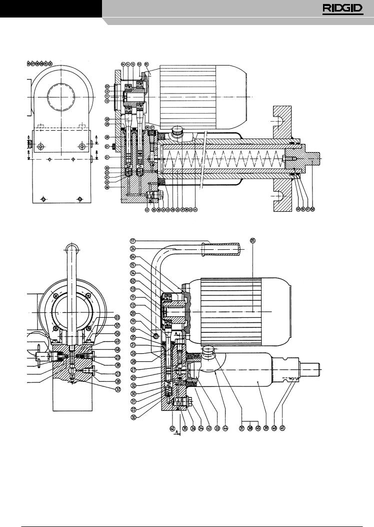
Maintenance
The bender is delivered with a filled oil container. However, the oil level must be checked regularly as otherwise the stroke of the ram will become too short. Oil must always be level with the bottom of the filling cap. If oil needs to be added, use only hydraulic oil.
Caution
1.Ensure that corner supports are always adjusted symmetrically in the holes, according to the size of the pipe to be bent. If not placed properly, the ram instead of the pipe may be bent and the machine badly damaged.
2.Also take care that fixing-pins for corner supports are properly fitted through the holes in the upper and under wing of the bending frame, and all the way through on the open bending frame.
3.The ram must not be moved out beyond the groove mark.
Faults which may occur and how they can be corrected
Numbers in brackets refer to electric machines. |
|
|
FAULT |
POSSIBLE CAUSE |
HOW TO CORRECT |
1. The ram (33) will not move out far enough. |
a. The filling cap (37) is not loosened sufficiently. |
a. Release filling cap (37) about 1 or 1 1/2 turns. |
|
|
When removing the machine take care that |
|
|
filling cap is closed tightly. |
b. The oil container is not filled sufficiently.
b.Refill oil container until oil is level with bottom of filling cap. The ram should not be pumped out beyond the groove mark on the ram.
2. The ram (33) will not move out at all.
3.The ram (33) gives only little or no pressure at all.
4.The pump handle (16) will not come up again.
5.The ram (33) will not reverse when relief spindle is loosened.
6.Oil leaks from press ram (20).
c. Air vent in filling cap (37) is blocked.
a.The relief spindle (7) is not tightened enough.
b.Ball (32) does not lock when pressing; possibly dirt on ball cone.
c.Filter (42) and/or oil supply channel is clogged.
a.Relief spindle (7) is not tightened.
b.Because of dirt between cone and ball (32) of the relief spindle (7), oil is leaking back to the oil container.
c.Ball (32) does not lock because of dirty cone.
d.Packing under safety screw for pull spring (27) is leaking.
e.Packing (40) is leaking.
f.Press packing (46) is leaking.
a.Press spring (30) is damaged.
a.Pull spring (29) is damaged.
b. Ram (33) is bent. This can only happen because of unsymmetrically placed corner supports.
a. Scraper packing (41) is leaking.
c. Clean air vent hole.
a. Tighten the relief spindle.
b1. Clean ball cone under ball (32). Eventuallly knock ball on cone for tighter fit.
b2. Please contact supplier.
c.Remove lock pin (34). Clean filter and oil supply channel.
a.Tighten the relief spindle.
b.Detach relief spindle (7), ring nut (8), packing
(9)and bottom rings (10). Clean cone for ball
(31).See 2b1. (If necessary contact supplier).
c.Detach safety screw for pull spring (27) and pull out the ram about 2 cm (1”). See 2b1.
d.Tighten this screw and if necessary replace joint ring (28).
e.Replace packing. Take care that it is properly locked. For detaching ram see 3c.
f.Replace packing.
a.Replace press spring.
a.Replace pull spring. Please contact supplier.
b.Please contact supplier.
a.Replace scraper packing. If necessary also replace packing (46).
2 |
Ridge Tool Company |

3801(E), 3802(E), 3811(E), 3812(E), 3813(E), 3814(E)
|
|
no. |
Model |
|
Model |
|
Model |
|
Model |
|
Model |
|
Model |
|
|
|
Model |
|
Model |
|
no. |
||
|
|
Pos. |
3801/ |
QTY |
3802/ |
QTY |
QTY |
QTY |
QTY |
3802 E |
|
QTY |
|
QTY |
QTY |
Pos. |
|||||||
|
|
3813 |
3814 |
3801 E |
|
|
3813 E |
3814 E |
|||||||||||||||
|
|
3811 |
|
3812 |
|
|
|
|
|
|
|
3812 E |
|
|
|
|
|
|
|
|
|
||
|
|
|
|
|
|
|
|
|
|
|
|
|
|
|
|
|
|
|
|
|
|||
Screw |
|
01 |
|
|
|
|
|
|
|
|
21256 |
4 |
21256 |
|
4 |
|
21256 |
4 |
28256 |
4 |
01 |
||
Covering cap |
|
02 |
|
|
|
|
|
|
|
|
21266 |
1 |
21266 |
|
1 |
|
21266 |
1 |
21266 |
1 |
02 |
||
Screw |
|
03 |
|
|
|
|
|
|
|
|
21276 |
4 |
21276 |
|
4 |
|
21276 |
4 |
21276 |
4 |
03 |
||
Driving case |
|
04 |
|
|
|
|
|
|
|
|
21286 |
1 |
21286 |
|
1 |
|
21286 |
1 |
28736 |
1 |
04 |
||
Electro motor |
|
05 |
|
|
|
|
|
|
|
|
See table |
1 |
See table |
|
1 |
See table |
1 |
See table |
1 |
05 |
|||
Notch pin for relief spindle |
|
06 |
21126 |
1 |
21126 |
1 |
21126 |
1 |
21126 |
1 |
21126 |
1 |
21126 |
|
1 |
|
21126 |
1 |
21126 |
1 |
06 |
||
Relief spindle |
|
07 |
21116 |
1 |
21116 |
1 |
21116 |
1 |
21116 |
1 |
21116 |
1 |
21116 |
|
1 |
|
21116 |
1 |
21116 |
1 |
07 |
||
Ringnut for relief spindle |
|
08 |
21106 |
1 |
21106 |
1 |
21106 |
1 |
21106 |
1 |
21106 |
1 |
21106 |
|
1 |
|
21106 |
1 |
21106 |
1 |
08 |
||
Rubber packing |
|
09* |
|
1 |
|
1 |
|
1 |
|
1 |
|
1 |
|
|
1 |
|
|
|
|
1 |
|
1 |
09 |
Copper bottom ring |
|
10* |
|
2 |
|
2 |
|
2 |
|
2 |
|
2 |
|
|
2 |
|
|
|
|
2 |
|
2 |
10 |
Screw |
|
11 |
|
|
|
|
|
|
|
|
21376 |
1 |
21376 |
|
2 |
|
21376 |
2 |
21376 |
2 |
11 |
||
Safety ring |
|
12 |
|
|
|
|
|
|
|
|
21386 |
1 |
21386 |
|
1 |
|
21386 |
1 |
21386 |
1 |
12 |
||
Lock nut |
|
13 |
|
|
|
|
|
|
|
|
21396 |
1 |
21396 |
|
1 |
|
21396 |
1 |
21396 |
1 |
13 |
||
Ball bearing |
|
14 |
|
|
|
|
|
|
|
|
21406 |
1 |
21406 |
|
1 |
|
21406 |
1 |
21406 |
1 |
14 |
||
Excentric |
|
15 |
|
|
|
|
|
|
|
|
21416 |
1 |
21416 |
|
1 |
|
21416 |
1 |
28606 |
1 |
15 |
||
Hand lever |
|
16 |
20846 |
1 |
20846 |
1 |
20846 |
1 |
28726 |
1 |
|
|
|
|
|
|
|
|
|
|
|
|
16 |
Handle |
|
17* |
|
1 |
|
1 |
|
1 |
|
1 |
|
1 |
|
|
1 |
|
|
|
|
1 |
|
|
17 |
Safety ring |
|
18 |
21076 |
2 |
21076 |
2 |
21076 |
2 |
28746 |
2 |
21076 |
2 |
21076 |
|
2 |
|
21976 |
2 |
|
|
18 |
||
Notch pin |
|
19 |
21066 |
1 |
21066 |
1 |
21066 |
1 |
28516 |
1 |
21066 |
1 |
21066 |
|
1 |
|
21066 |
1 |
|
|
19 |
||
Press ram |
|
20 |
20866 |
1 |
20866 |
1 |
20866 |
1 |
28596 |
1 |
21466 |
1 |
21466 |
|
1 |
|
21466 |
1 |
21466 |
2 |
20 |
||
Press ram housing |
|
21 |
|
|
|
|
|
|
|
|
21476 |
1 |
21476 |
|
1 |
|
21476 |
1 |
21476 |
2 |
21 |
||
Notch pin dia 4 x16 |
|
22 |
|
|
|
|
|
|
|
|
21486 |
1 |
21486 |
|
1 |
|
21486 |
1 |
21486 |
2 |
22 |
||
Terminal plug G 1/4” |
|
23 |
20926 |
1 |
20926 |
1 |
20926 |
1 |
20926 |
1 |
20926 |
1 |
20926 |
|
1 |
|
20926 |
1 |
20926 |
2 |
23 |
||
Carrying yoke |
|
24 |
|
|
|
|
|
|
|
|
21426 |
1 |
21426 |
|
1 |
|
21426 |
1 |
|
|
24 |
||
Scraper packing for press ram |
25* |
|
1 |
|
1 |
|
1 |
|
1 |
|
1 |
|
|
1 |
|
|
|
|
1 |
|
2 |
25 |
|
O-Ring |
|
26* |
|
|
|
|
|
|
|
|
|
2 |
|
|
2 |
|
|
|
|
2 |
|
4 |
26 |
Safety screw for pull spring |
27 |
20916 |
1 |
20916 |
1 |
20916 |
1 |
28636 |
1 |
21526 |
1 |
21526 |
|
1 |
|
21526 |
1 |
28866 |
2 |
27 |
|||
Joint ring PP 45 B |
|
28* |
|
2 |
|
2 |
|
2 |
|
2 |
|
3 |
|
|
3 |
|
|
|
|
3 |
|
4 |
28 |
Pull spring 1 1/4” |
|
29 |
21166 |
1 |
21176 |
1 |
21176 |
1 |
28496 |
1 |
21166 |
1 |
21176 |
|
1 |
|
21176 |
1 |
28496 |
1 |
29 |
||
Push spring |
|
30 |
20896 |
1 |
20896 |
1 |
20896 |
1 |
28476 |
1 |
21536 |
1 |
21536 |
|
1 |
|
21536 |
1 |
21536 |
2 |
30 |
||
Ball cone |
|
31 |
|
|
|
|
|
|
|
|
21546 |
1 |
21546 |
|
1 |
|
21546 |
1 |
21546 |
2 |
31 |
||
Ball 5/16” |
|
32* |
|
3 |
|
3 |
|
3 |
|
3 |
|
4 |
|
|
4 |
|
|
|
|
4 |
|
6 |
32 |
Ram 1 1/4” |
|
33 |
21186 |
1 |
21196 |
1 |
21206 |
1 |
28586 |
1 |
21186 |
1 |
21196 |
|
1 |
|
21206 |
1 |
28586 |
1 |
33 |
||
Plug G 1/2” |
|
34 |
21026 |
1 |
21026 |
1 |
21126 |
1 |
21026 |
1 |
21026 |
1 |
21026 |
|
1 |
|
21026 |
1 |
21026 |
1 |
34 |
||
Push spring for filter |
|
35 |
21576 |
1 |
21576 |
1 |
21576 |
1 |
21576 |
1 |
21576 |
1 |
21576 |
|
1 |
|
21576 |
1 |
21576 |
1 |
35 |
||
Joint ring PP 45 D |
|
36* |
|
1 |
|
1 |
|
1 |
|
1 |
|
1 |
|
|
1 |
|
|
|
|
1 |
|
1 |
36 |
Filling cap |
|
37 |
20946 |
1 |
20946 |
1 |
20946 |
1 |
20946 |
1 |
20946 |
1 |
20946 |
|
1 |
|
20946 |
1 |
20946 |
1 |
37 |
||
Cork packing for filling cap |
|
38* |
|
1 |
|
1 |
|
1 |
|
1 |
|
1 |
|
|
1 |
|
|
|
|
1 |
|
1 |
38 |
Pump body |
|
39 |
|
1 |
|
1 |
|
1 |
|
1 |
|
1 |
|
|
1 |
|
|
|
|
1 |
|
1 |
39 |
Packing 1 1/4” |
|
40* |
20996 |
1 |
21006 |
1 |
21016 |
1 |
28466 |
1 |
20996 |
1 |
21006 |
|
1 |
|
21016 |
1 |
28466 |
1 |
40 |
||
Scraper packing |
|
41* |
|
1 |
|
1 |
|
1 |
|
1 |
|
1 |
|
|
1 |
|
|
|
|
1 |
|
1 |
41 |
Filter |
|
42* |
|
1 |
|
1 |
|
1 |
|
1 |
|
1 |
|
|
1 |
|
|
|
|
1 |
|
1 |
42 |
Pin for pull spring |
|
43 |
21136 |
1 |
21146 |
1 |
21156 |
1 |
28556 |
1 |
21136 |
1 |
21146 |
|
1 |
|
21156 |
1 |
28556 |
1 |
43 |
||
Disc |
|
44 |
21246 |
1 |
21246 |
1 |
21246 |
1 |
21246 |
1 |
21246 |
1 |
21246 |
|
1 |
|
21246 |
1 |
21246 |
1 |
44 |
||
Hydraulic fluid (2,5 l) |
|
45 |
14061 |
1 |
14061 |
1 |
14061 |
1 |
14061 |
1 |
14061 |
1 |
14061 |
|
1 |
|
14061 |
1 |
14061 |
1 |
45 |
||
Press packing |
|
46* |
|
1 |
|
1 |
|
1 |
|
1 |
|
|
|
|
|
|
|
|
|
|
|
|
46 |
Pin for press packing |
|
47 |
20886 |
1 |
20866 |
1 |
20866 |
1 |
20886 |
1 |
|
|
|
|
|
|
|
|
|
|
|
|
47 |
Plug for safety valve |
|
48 |
|
|
|
|
|
|
|
|
28576 |
1 |
28576 |
|
1 |
|
28576 |
1 |
28576 |
1 |
48 |
||
Spring |
|
49 |
|
|
|
|
|
|
|
|
28486 |
24 |
28486 |
|
24 |
|
28486 |
24 |
28486 |
24 |
49 |
||
Ballcone |
|
50 |
|
|
|
|
|
|
|
|
28626 |
1 |
28626 |
|
1 |
|
28626 |
1 |
28626 |
1 |
50 |
||
O-ring |
|
51* |
|
|
|
|
|
|
28426 |
1 |
|
|
|
|
|
|
|
|
|
|
28426 |
1 |
51 |
Plug for ram 4” |
|
52 |
|
|
|
|
|
|
28616 |
1 |
|
|
|
|
|
|
|
|
|
|
28616 |
1 |
52 |
Seal kits (includes items with*) |
|
21906 |
|
21916 |
|
21926 |
|
33226 |
|
21936 |
|
21946 |
|
|
|
21956 |
|
33236 |
|
|
|||
|
|
|
|
|
|
|
|
|
|
|
|
|
|
|
|
|
|
|
|
|
|
|
|
|
|
|
|
|
|
|
|
|
|
|
|
|
|
|
|
|
|
|
|
|
|
|
|
Motor 110V 1Ø |
28276 |
Capacitor |
230V = 40μ F |
34306 |
|
|
|
|
|
Switch |
110V |
|
|
1Ø |
|
57786 |
|
|
|||||
|
|
|
|
|
|
|
|
|
|
||||||||||||||
230V 1Ø |
21316 |
|
|
110V = 110μ F |
34316 |
|
|
|
|
|
|
|
230V |
|
|
|
57776 |
|
|
||||
|
|
|
|
|
|
|
|
|
|
|
|
|
|
|
|||||||||
400V 3Ø |
21306 |
|
|
|
|
|
|
|
|
|
|
|
|
400V |
3Ø |
|
57766 |
|
|
||||
Ridge Tool Company |
3 |
3801(E), 3802(E), 3811(E), 3812(E), 3813(E), 3814(E)
4 |
Ridge Tool Company |

3801(E), 3802(E), 3811(E), 3812(E), 3813(E), 3814(E)
Accessories
|
|
3802 |
|
3812 |
|
3813 |
|
|
|
|
|
|
||||
|
|
|
|
|
|
|
|
|
|
|
|
|
|
|
|
|
180° Attachment |
|
22366 |
|
22346 |
|
22356 |
|
See bending formers |
||||||||
|
|
|
|
|
|
|
|
|
|
|
|
|
|
|
|
|
40 x 8 mm |
|
22446 |
|
22436 |
|
22456 |
|
See below for formers |
||||||||
Bar attachment |
|
|
|
|
||||||||||||
|
|
|
|
|
|
|
|
|
|
|
|
|
|
|
|
|
|
|
|
|
|
|
|
|
|
|
|
|
|
|
|
||
|
|
|
3801 E / 3811 E2 |
|
3802 E / 12 E / 13 E |
|
3814 E |
|||||||||
Stroke |
|
|
|
|
|
|
|
|
|
|
|
|
|
|
||
|
|
220 V |
26896 |
|
|
26916 |
|
|
29126 |
|||||||
adjustment |
|
|
360 V |
26906 |
|
|
26926 |
|
|
29116 |
||||||
|
|
|
115 V |
35116 |
|
|
34916 |
|
|
35726 |
||||||
|
|
|
|
|
|
|
|
|
|
|
|
|||||
Radius (mm) |
60 |
70 |
|
80 |
|
90 |
100 |
110 |
|
120 |
130 |
|||||
|
|
|
|
|
|
|
|
|
|
|
|
|
|
|
|
|
40 x 8 mm |
22466 |
22476 |
|
22486 |
22496 |
22506 |
22516 |
22526 |
22536 |
|||||||
Bar formers |
|
|||||||||||||||
|
|
|
|
|
|
|
|
|
|
|
|
|
|
|
|
|
Bending Formers
Nominal |
Outside |
Standard formers |
Boiler |
tube |
180 Deg. bends |
|||
Size |
Ø |
Radius |
Cat. No. |
Radius |
Cat. No. |
Radius |
Cat. No. |
|
mm |
||||||||
1/4 |
13.5 |
60 |
28286 |
|
|
130 |
22376 |
|
3/8 |
17.2 |
45 |
21806 |
|
|
|
|
|
18 |
18 |
60 |
27816 |
|
|
|
|
|
20 |
20 |
70 |
27826 |
|
|
|
|
|
1/2 |
21.3 |
50 |
21816 |
110 |
22236 |
130 |
22386 |
|
22 |
22 |
80 |
27836 |
|
|
|
|
|
25 |
25 |
115 |
22116 |
|
|
|
|
|
3/4” |
26.9 |
65 |
21826 |
137 |
22246 |
130 |
22396 |
|
28 |
28 |
70 |
35066 |
|
|
|
|
|
30 |
30 |
140 |
22126 |
|
|
|
|
|
32 |
32 |
140 |
22136 |
|
|
|
|
|
1 |
|
33.7 |
100 |
21836 |
190 |
22256 |
130 |
22406 |
35 |
35 |
100 |
35076 |
|
|
|
|
|
38 |
38 |
170 |
22146 |
|
|
|
|
|
40 |
40 |
125 |
35086 |
|
|
|
|
|
42 |
42 |
125 |
35096 |
|
|
|
|
|
1 |
1/4” |
42.4 |
130 |
21846 |
220 |
22266 |
130 |
22416 |
44.5 |
44.5 |
190 |
22156 |
|
|
|
|
|
1 |
1/2 |
48.3 |
160 |
21856 |
220 |
22166 |
140 |
22426 |
50 |
50 |
140 |
35106 |
|
|
|
|
|
51 |
51 |
220 |
22176 |
|
|
|
|
|
57 |
57 |
250 |
22186 |
|
|
|
|
|
2 |
|
60.3 |
220 |
21866 |
270 |
22196 |
190 |
28766 |
63.5 |
63.5 |
270 |
22206 |
|
|
|
|
|
70 |
70 |
315 |
22216 |
|
|
|
|
|
2 |
1/2 |
76.1 |
320 |
21876 |
420 |
22226 |
|
|
3 |
|
88.9 |
380 |
21886 |
|
|
|
|
4 |
|
114.3 |
600 |
28756 |
|
|
|
|
Ridge Tool Company |
5 |
3801(E), 3802(E), 3811(E), 3812(E), 3813(E), 3814(E)
DE
3801(E), 3802(E), 3811(E), 3812(E), 3813(E), 3814(E)
Bedienungsanleitung
WARNUNG! Lesen Sie diese Anweisungen und die begleitende Sicherheitsbroschüre sorgfältig, bevor Sie dieses Gerät benutzen. Bei Unklarheiten wenden Sie
sich bitte an Ihre RIDGID Vertriebsstelle, die Sie näher informiert.
UnkenntnisundNichtbefolgungderAnweisungen können zu elektrischen Schlägen, Feuer und/ oder schweren Verletzungen führen.
BEWAHREN SIE DIESE ANWEISUNGEN AUF!
Montage
1.a. 1 1/4”, 2” und 3” Maschinen.
Den Biegerahmen mit Stützen auf den Boden stellen und den Ring vorne über den Pumpenzylinder schieben.
Den U-Bügel durch die Öffnungen im Ringblock am Biegerahmen
einsetzen. Pumpenzylinder und Rohrbiegerahmen sind jetzt korrekt befestigt.
1.b. 4” Maschine.
-Die Grundschiene auf den Boden legen.
-Den unteren Flügel auf die Grundschiene legen.
-Die Biegepumpe auf die Grundschiene legen, den unteren Flügel in die Pumpe einhaken und die Pumpe an der Rückseite mit zwei M10 Schrauben befestigen.
-Die Eckstützen und das Biegesegment, das Sie benutzen wollen, auf den unteren Flügel legen.
-Den oberen Flügel auf die Eckstützen legen und in der Pumpe einhaken.
-Die Fixierstifte durch die Flügel und die Eckstützen stecken.
MONTAGE DER 4” MASCHINE
Oberer Flügel
4” Pumpe Eckstütze 
mit Fixierstiften
Unterer Flügel
 Grundschiene
2.Ein Biegesegment, das dem Durchmesser des zu biegenden Rohrs entspricht, am Kolbenkopf anbringen. Die Eckstützen müssen zwischen oder auf dem Biegerahmen angebracht werden. Sie werden mittels der Fixierstifte befestigt. Die Öffnungen im Rahmen ermöglichen das Einstellen der Eckstützen auf die gewünschten Außendurchmesser. Die Öffnungen sind entsprechend markiert.
Vergewissern, dass die Fixierstifte für die Eckstützen korrekt durch beide Flügel oder durch den Biegerahmen geführt sind, um Schäden zu vermeiden.
Biegen
1.Der Fülldeckel ist zwecks Entlüftung durchstochen. Beim Transport der Biegemaschine muss dieser Deckel fest verschlossen sein und während der Benutzung ein wenig gelöst werden.
2.Vor dem Biegen sollte das Rohr leicht gefettet werden. Das Rohr wird zwischen Eckstützen und Biegesegment geschoben. Die Entlastungsspindel muss fest angezogen werden. Durch Aufund Abbewegen des Griffs wird die Pumpe betätigt. Der Kolbenkopf bewegt sich heraus und das Rohr wird gebogen. Der Biegevorgang sollte fortgesetzt werden, bis die gewünschte Krümmung erreicht ist, jedoch nicht weiter als bis zur Krümmung des Biegesegments. Abhängig von der Qualität federt das Rohr ein wenig zurück.Dies muss durch Experimentieren ermittelt werden.
3.Sobald das Rohr die gewünschte Form erreicht hat, Entlastungsspindel lösen, der Kolben zieht sich dann automatisch zurück. Eine der Eckstützen lösen, dann lässt sich das Rohr entfernen. Die mit offenem Rahmen ausgestatteten Modelle haben den Vorteil, dass sich das gebogene Rohr leichter entfernen lässt, insbesondere bei langen Rohrstücken mit mehreren Biegungen spart man dadurch viel Zeit.
4.Wenn ein Rohr zu weit gebogen wurde, lässt sich dies mit der Richtvorrichtung wieder korrigieren. Der Kolben muss zurückgezogen und das Rohr gegen die Eckstützen gedreht werden. Die Richtvorrichtung wird oben auf dem Kolben angebracht und die Biegung kann in die gewünschte Form zurückgedrückt werden. Mit der 1 1/4” Biegemaschine lässt sich eine Krümmung von 90° normalerweise nicht korrigieren. Dies gilt auch bei der 3” Maschine für 2 1/2” und 3”, sowie bei der 4” Maschine für 3” und 4” Rohre.
5.Nur für 3” und 4” Modell.
Beim Biegen von 2 1/2”, 3” und 4” Rohre sollte eine Verlängerung am Kolben angebracht werden, wenn das Rohr weiter als 75° gebogen wurde. Der Kolbenweg reicht nicht aus, um eine 90°-Krümmung in einem Arbeitsgang zu biegen.
6.1 1/4”, 2”, 3”, 4” elektrohydraulische Rohrbiegemaschinen. Die elektrohydraulischen Rohrbiegemaschinen sind mit einem einphasigen 115 V, 220 V Wechselstromoder einem 380 V Dreiphasenmotor ausgestattet. Der Motor verfügt über einen speziellen Sicherheitsschalter. Bei laufendem Motor wird die Kolbenbewegung durch eine Entlastungsspindel gesteuert, die geöffnet oder geschlossen werden kann. Der Motor muss nicht
ausgeschaltet werden. Darüber hinaus ist die Maschine auch mit einem Drucksicherheitsventil versehen. Dieses Ventil wird im Werk so eingestellt, dass dickwandige Rohre (3” Dampfrohre) ohne Probleme gebogen werden können. Das Drucksicherheitsventil befindet sich im Pumpengehäuse und kann ausschließlich anhand eines Manometers eingestellt werden.
Haarnadelbiegungen von 180°
Hierfür ist Sonderzubehör erforderlich, das auf Anfrage lieferbar ist.
Montage
1.Siehe Montage Rohrbiegemaschinen.
2.Das Biegesegment (180°) wird entsprechend der Rohrgröße am Kolben befestigt. Nun werden die Platten (Ersatzrahmen) mit 3 Rollen (Doppelkegel) zwischen oder im Rahmen eingestellt. Die Fixierstifte für die Eckstück müssen in die 1 1/4” Öffnungen im Zentralverschluss gesteckt werden; der abnehmbare Doppelkegel muss entfernt und das zu biegende Rohr durchgeschoben werden. Das Rohr muss nun den mittleren Doppelkegel mit einer Seite und das 180°-Biegesegment mit der anderen Seite berühren. Der Biegevorgang kann nun beginnen.
6 |
Ridge Tool Company |

3801(E), 3802(E), 3811(E), 3812(E), 3813(E), 3814(E)
Biegen
1.Siehe unter Biegen.
2.Bei einer Krümmung von mehr als 90° muss der Kolben durch Lösen der Entlastungsspindel umgedreht werden. Die abnehmbaren Doppelkegel entfernen und eine Biegung um bis zu 180° vornehmen. Entfernen des gebogenen Rohrs siehe Biegen.
Wartung
Die Biegevorrichtung wird mit gefülltem Ölbehälter geliefert. Der Ölstand muss jedoch regelmäßig kontrolliert werden, da andernfalls der Kolbenhub zu kurz wird. Der Ölstand muss immer dem unteren Rand des Fülldeckels entsprechen. Wenn Öl nachgefüllt werden muss, nur Hydrauliköl verwenden.
Achtung
1.Es ist darauf zu achten, dass die Eckstützen, entsprechend der Größe des zu biegenden Rohrs, stets symmetrisch in die Öffnungen eingesetzt werden. Wenn sie nicht korrekt platziert sind, kann der Kolben statt des Rohrs verbogen werden, sodass die Maschine schwer beschädigt wird.
2.Außerdem muss darauf geachtet werden, dass die Fixierstifte für die Eckstützen korrekt durch die Öffnungen im oberen und unteren Flügel des Biegerahmens und vollständig durch den offenen Biegerahmen gesteckt werden.
3.Der Kolben darf nicht über die Markierungskerbe hinaus nach außen bewegt werden.
Mögliche Fehler und wie man sie beheben kann
Die Nummern in Klammern beziehen sich auf die elektrischen Maschinen.
STÖRUNG |
MÖGLICHE URSACHE |
ABHILFE |
1.Der Kolben (33) bewegt sich nicht weit genug nach vorne.
a.Fülldeckel (37) ist nicht ausreichend geöffnet.
b.Der Ölbehälter ist nicht voll genug.
a.Fülldeckel (37) um 1 oder 1 1/2 Umdrehungen öffnen. Beim Transport der Maschine darauf achten, dass der Fülldeckel wieder fest verschlossen wird.
b.Öl nachfüllen bis der Füllstand den unteren Rand des Fülldeckels erreicht. Den Kolben nicht über die Markierungskerbe auf dem Kolben herauspumpen.
2.Der Kolben (33) bewegt sich überhaupt nicht nach vorne.
3.Der Kolben (33) übt nur geringen bzw. gar keinen Druck aus.
4.Pumpengriff (16) bewegt sich nicht mehr nach oben.
5.Kolben (33) bewegt sich nicht mehr zurück, wenn die
Entlastungsspindel gelöst wird.
6.Öl tritt aus Kolben (20) aus.
c. Entlüftungsöffnung im Fülldeckel (37) ist verschlossen.
a.Die Entlastungsspindel (7) ist nicht genügend zugedreht.
b.Kugel (32) schließt nicht unter Druck; Kugelkonus eventuell verschmutzt.
c.Filter (42) und/oder Ölleitung verstopft.
a.Die Entlastungsspindel (7) ist nicht zugedreht.
b.Wegen Schmutz zwischen Konus und Kugel (32) der Entlastungsspindel (7) läuft Öl in den Ölbehälter zurück.
c.Kugel (32) schließt nicht wegen verschmutztem Konus.
d.Dichtung unter Sicherheitsschraube für Zugfeder 9 (27) leckt.
e.Dichtung (40) leckt.
f.Druckdichtung (46) leckt.
a.Druckfeder (30) ist beschädigt. a. Zugfeder (29) ist beschädigt.
b. Kolben (33) ist verbogen. Dies kann nur geschehen, wenn die Eckstützen nicht symmetrisch platziert wurden.
a. Ölabstreifdichtung (41) leckt.
c. Entlüftungsöffnung reinigen. a. Entlastungsspindel anziehen.
b1. Kugelkonus unter Kugel (32) reinigen.
Für festeren Sitz eventuell auf Kugel an Konus klopfen.
b2. Bitte wenden Sie sich an den Händler.
c.Sicherungsstift (34) entfernen. Filter und Ölleitung reinigen.
a.Entlastungsspindel anziehen.
b.Entlastungsspindel (7), Ringmutter (8), Dichtung (9) und untere Ringe (10) lösen. Konus für Kugel (31) reinigen. Siehe 2b1. (Bei Bedarf wenden Sie sich bitte an den Händler).
c.Sicherheitsschraube für Zugfeder (27) lösen und Kolben etwa 2 cm (1”) herausziehen. Siehe 2b1.
d.Diese Schraube anziehen und nötigenfalls Dichtungsring (28) ersetzen.
e.Dichtung ersetzen. Auf korrekte Befestigung achten. Lösen siehe 3c.
f.Dichtung ersetzen.
a.Druckfeder ersetzen.
a.Zugfeder ersetzen. Bitte wenden Sie sich an den Händler.
b.Bitte wenden Sie sich an den Händler.
a.Ölabstreifdichtung ersetzen. Auch Dichtung (46) muss ersetzt werden.
Ridge Tool Company |
7 |

3801(E), 3802(E), 3811(E), 3812(E), 3813(E), 3814(E)
|
|
Nr. |
Modell |
|
Modell |
|
Modell |
|
Modell |
|
Modell |
|
Modell |
|
|
Modell |
|
Modell |
|
Nr. |
||
|
|
Pos. |
3801/ |
STCK. |
3802/ |
STCK. |
STCK. |
STCK. |
STCK. |
3802 E |
STCK. |
|
STCK. |
STCK. |
Pos. |
|||||||
|
|
3813 |
3814 |
3801 E |
|
3813 E |
3814 E |
|||||||||||||||
|
|
3811 |
|
3812 |
|
|
|
|
|
|
|
3812 E |
|
|
|
|
|
|
|
|
||
|
|
|
|
|
|
|
|
|
|
|
|
|
|
|
|
|
|
|
|
|||
|
Schraube |
01 |
|
|
|
|
|
|
|
|
21256 |
4 |
21256 |
4 |
|
21256 |
4 |
28256 |
4 |
01 |
||
|
Deckel |
02 |
|
|
|
|
|
|
|
|
21266 |
1 |
21266 |
1 |
|
21266 |
1 |
21266 |
1 |
02 |
||
|
Schraube |
03 |
|
|
|
|
|
|
|
|
21276 |
4 |
21276 |
4 |
|
21276 |
4 |
21276 |
4 |
03 |
||
|
Antriebsgehäuse |
04 |
|
|
|
|
|
|
|
|
21286 |
1 |
21286 |
1 |
|
21286 |
1 |
28736 |
1 |
04 |
||
|
Elektromotor |
05 |
|
|
|
|
|
|
|
|
Siehe |
1 |
Siehe |
1 |
|
|
Siehe |
1 |
Siehe |
1 |
05 |
|
|
|
|
|
|
|
|
|
|
|
|
Tabelle |
|
Tabelle |
|
|
Tabelle |
|
Tabelle |
|
|
||
|
Raststift für Entlastungsspindel 06 |
21126 |
1 |
21126 |
1 |
21126 |
1 |
21126 |
1 |
21126 |
1 |
21126 |
1 |
|
21126 |
1 |
21126 |
1 |
06 |
|||
|
Entlastungsspindel |
07 |
21116 |
1 |
21116 |
1 |
21116 |
1 |
21116 |
1 |
21116 |
1 |
21116 |
1 |
|
21116 |
1 |
21116 |
1 |
07 |
||
|
Ringmutter für |
|
|
|
|
|
|
|
|
|
|
|
|
|
|
|
|
|
|
|
|
|
|
Entlastungsspindel |
08 |
21106 |
1 |
21106 |
1 |
21106 |
1 |
21106 |
1 |
21106 |
1 |
21106 |
1 |
|
21106 |
1 |
21106 |
1 |
08 |
||
|
Gummidichtung |
09* |
|
1 |
|
1 |
|
1 |
|
1 |
|
1 |
|
1 |
|
|
|
|
1 |
|
1 |
09 |
|
Unterer Kupferring |
10* |
|
2 |
|
2 |
|
2 |
|
2 |
|
2 |
|
2 |
|
|
|
|
2 |
|
2 |
10 |
|
Schraube |
11 |
|
|
|
|
|
|
|
|
21376 |
1 |
21376 |
2 |
|
21376 |
2 |
21376 |
2 |
11 |
||
|
Sicherheitsring |
12 |
|
|
|
|
|
|
|
|
21386 |
1 |
21386 |
1 |
|
21386 |
1 |
21386 |
1 |
12 |
||
|
Kontermutter |
13 |
|
|
|
|
|
|
|
|
21396 |
1 |
21396 |
1 |
|
21396 |
1 |
21396 |
1 |
13 |
||
|
Kugellager |
14 |
|
|
|
|
|
|
|
|
21406 |
1 |
21406 |
1 |
|
21406 |
1 |
21406 |
1 |
14 |
||
|
Exzenter |
15 |
|
|
|
|
|
|
|
|
21416 |
1 |
21416 |
1 |
|
21416 |
1 |
28606 |
1 |
15 |
||
|
Hebel |
16 |
20846 |
1 |
20846 |
1 |
20846 |
1 |
28726 |
1 |
|
|
|
|
|
|
|
|
|
|
|
16 |
|
Handgriff |
17* |
|
1 |
|
1 |
|
1 |
|
1 |
|
1 |
|
1 |
|
|
|
|
1 |
|
|
17 |
|
Sicherheitsring |
18 |
21076 |
2 |
21076 |
2 |
21076 |
2 |
28746 |
2 |
21076 |
2 |
21076 |
2 |
|
21976 |
2 |
|
|
18 |
||
|
Raststift |
19 |
21066 |
1 |
21066 |
1 |
21066 |
1 |
28516 |
1 |
21066 |
1 |
21066 |
1 |
|
21066 |
1 |
|
|
19 |
||
|
Presskolben |
20 |
20866 |
1 |
20866 |
1 |
20866 |
1 |
28596 |
1 |
21466 |
1 |
21466 |
1 |
|
21466 |
1 |
21466 |
2 |
20 |
||
|
Presskolbengehäuse |
21 |
|
|
|
|
|
|
|
|
21476 |
1 |
21476 |
1 |
|
21476 |
1 |
21476 |
2 |
21 |
||
|
Raststift Durchmesser 4 x16 |
22 |
|
|
|
|
|
|
|
|
21486 |
1 |
21486 |
1 |
|
21486 |
1 |
21486 |
2 |
22 |
||
|
Verschlussstopfen G 1/4” |
23 |
20926 |
1 |
20926 |
1 |
20926 |
1 |
20926 |
1 |
20926 |
1 |
20926 |
1 |
|
20926 |
1 |
20926 |
2 |
23 |
||
|
Tragebügel |
24 |
|
|
|
|
|
|
|
|
21426 |
1 |
21426 |
1 |
|
21426 |
1 |
|
|
24 |
||
|
Abstreifdichtung für Presskolben 25* |
|
1 |
|
1 |
|
1 |
|
1 |
|
1 |
|
1 |
|
|
|
|
1 |
|
2 |
25 |
|
|
O-Ring |
26* |
|
|
|
|
|
|
|
|
|
2 |
|
2 |
|
|
|
|
2 |
|
4 |
26 |
|
Sicherheitsschraube für |
|
|
|
|
|
|
|
|
|
|
|
|
|
|
|
|
|
|
|
|
|
|
Zugfeder |
27 |
20916 |
1 |
20916 |
1 |
20916 |
1 |
28636 |
1 |
21526 |
1 |
21526 |
1 |
|
21526 |
1 |
28866 |
2 |
27 |
||
|
Dichtungsring PP 45 B |
28* |
|
2 |
|
2 |
|
2 |
|
2 |
|
3 |
|
3 |
|
|
|
|
3 |
|
4 |
28 |
|
Zugfeder 1 1/4” |
29 |
21166 |
1 |
21176 |
1 |
21176 |
1 |
28496 |
1 |
21166 |
1 |
21176 |
1 |
|
21176 |
1 |
28496 |
1 |
29 |
||
|
Druckfeder |
30 |
20896 |
1 |
20896 |
1 |
20896 |
1 |
28476 |
1 |
21536 |
1 |
21536 |
1 |
|
21536 |
1 |
21536 |
2 |
30 |
||
|
Kugelkonus |
31 |
|
|
|
|
|
|
|
|
21546 |
1 |
21546 |
1 |
|
21546 |
1 |
21546 |
2 |
31 |
||
|
Kugel 5/16” |
32* |
|
3 |
|
3 |
|
3 |
|
3 |
|
4 |
|
4 |
|
|
|
|
4 |
|
6 |
32 |
|
Kolben 1 1/4” |
33 |
21186 |
1 |
21196 |
1 |
21206 |
1 |
28586 |
1 |
21186 |
1 |
21196 |
1 |
|
21206 |
1 |
28586 |
1 |
33 |
||
|
Stopfen G 1/2” |
34 |
21026 |
1 |
21026 |
1 |
21126 |
1 |
21026 |
1 |
21026 |
1 |
21026 |
1 |
|
21026 |
1 |
21026 |
1 |
34 |
||
|
Druckfeder für Filter |
35 |
21576 |
1 |
21576 |
1 |
21576 |
1 |
21576 |
1 |
21576 |
1 |
21576 |
1 |
|
21576 |
1 |
21576 |
1 |
35 |
||
|
Dichtungsring PP 45 D |
36* |
|
1 |
|
1 |
|
1 |
|
1 |
|
1 |
|
1 |
|
|
|
|
1 |
|
1 |
36 |
|
Fülldeckel |
37 |
20946 |
1 |
20946 |
1 |
20946 |
1 |
20946 |
1 |
20946 |
1 |
20946 |
1 |
|
20946 |
1 |
20946 |
1 |
37 |
||
|
Korkdichtung für Fülldeckel |
38* |
|
1 |
|
1 |
|
1 |
|
1 |
|
1 |
|
1 |
|
|
|
|
1 |
|
1 |
38 |
|
Pumpengehäuse |
39 |
|
1 |
|
1 |
|
1 |
|
1 |
|
1 |
|
1 |
|
|
|
|
1 |
|
1 |
39 |
|
Dichtung 1 1/4” |
40* |
20996 |
1 |
21006 |
1 |
21016 |
1 |
28466 |
1 |
20996 |
1 |
21006 |
1 |
|
21016 |
1 |
28466 |
1 |
40 |
||
|
Abstreifdichtung |
41* |
|
1 |
|
1 |
|
1 |
|
1 |
|
1 |
|
1 |
|
|
|
|
1 |
|
1 |
41 |
|
Filter |
42* |
|
1 |
|
1 |
|
1 |
|
1 |
|
1 |
|
1 |
|
|
|
|
1 |
|
1 |
42 |
|
Stift für Zugfeder |
43 |
21136 |
1 |
21146 |
1 |
21156 |
1 |
28556 |
1 |
21136 |
1 |
21146 |
1 |
|
21156 |
1 |
28556 |
1 |
43 |
||
|
Scheibe |
44 |
21246 |
1 |
21246 |
1 |
21246 |
1 |
21246 |
1 |
21246 |
1 |
21246 |
1 |
|
21246 |
1 |
21246 |
1 |
44 |
||
|
Hydraulikflüssigkeit (2,5 l) |
45 |
14061 |
1 |
14061 |
1 |
14061 |
1 |
14061 |
1 |
14061 |
1 |
14061 |
1 |
|
14061 |
1 |
14061 |
1 |
45 |
||
|
Druckdichtung |
46* |
|
1 |
|
1 |
|
1 |
|
1 |
|
|
|
|
|
|
|
|
|
|
|
46 |
|
Stift für Druckdichtung |
47 |
20886 |
1 |
20866 |
1 |
20866 |
1 |
20886 |
1 |
|
|
|
|
|
|
|
|
|
|
|
47 |
|
Stopfen für Sicherheitsventil |
48 |
|
|
|
|
|
|
|
|
28576 |
1 |
28576 |
1 |
|
28576 |
1 |
28576 |
1 |
48 |
||
|
Feder |
49 |
|
|
|
|
|
|
|
|
28486 |
24 |
28486 |
24 |
|
28486 |
24 |
28486 |
24 |
49 |
||
|
Kugelkonus |
50 |
|
|
|
|
|
|
|
|
28626 |
1 |
28626 |
1 |
|
28626 |
1 |
28626 |
1 |
50 |
||
|
O-Ring |
51* |
|
|
|
|
|
|
28426 |
1 |
|
|
|
|
|
|
|
|
|
28426 |
1 |
51 |
|
Stopfen für Kolben 4” |
52 |
|
|
|
|
|
|
28616 |
1 |
|
|
|
|
|
|
|
|
|
28616 |
1 |
52 |
|
Dichtungssätze (enthält Artikel mit*) |
21906 |
|
21916 |
|
21926 |
|
33226 |
|
21936 |
|
21946 |
|
|
21956 |
|
33236 |
|
|
|||
|
|
|
|
|
|
|
|
|
|
|
|
|
|
|
|
|
|
|
|
|
|
|
|
|
|
|
|
|
|
|
|
|
|
|
|
|
|
|
|
|
|
||||
|
Motor 110V 1Ø |
28276 |
Kondensator |
230V = 40μ F |
34306 |
|
|
|
|
|
Schalter 110V |
|
|
1Ø |
|
57786 |
|
|
||||
|
|
|
|
|
|
|
|
|
|
|
||||||||||||
|
230V 1Ø |
21316 |
|
|
110V = 110μ F |
34316 |
|
|
|
|
|
|
230V |
|
|
|
57776 |
|
|
|||
|
|
|
|
|
|
|
|
|
|
|
|
|
|
|
||||||||
|
|
|
|
|
|
|
|
|
|
|
|
|
|
|
||||||||
|
400V 3Ø |
21306 |
|
|
|
|
|
|
|
|
|
|
|
400V |
3Ø |
|
57766 |
|
|
|||
|
|
|
|
|
|
|
|
|
|
|
|
|
|
|
|
|
|
|
|
|
|
|
8 |
Ridge Tool Company |
3801(E), 3802(E), 3811(E), 3812(E), 3813(E), 3814(E)
Ridge Tool Company |
9 |
3801(E), 3802(E), 3811(E), 3812(E), 3813(E), 3814(E)
Zubehör
|
|
3802 |
|
3812 |
|
3813 |
|
|
|
|
|
|
|
||||
|
|
|
|
|
|
|
|
|
|
|
|
|
|
|
|
||
180° Zusatz |
|
22366 |
|
22346 |
|
22356 |
|
Siehe Biegesegmente |
|||||||||
|
|
|
|
|
|
|
|
|
|
|
|
|
|
|
|
|
|
40 x 8 mm |
|
22446 |
|
22436 |
|
22456 |
Biegesegmente siehe unten |
||||||||||
Stangenzusatz |
|
|
|
||||||||||||||
|
|
|
|
|
|
|
|
|
|
|
|
|
|
|
|
|
|
|
|
|
|
|
|
|
|
|
|
|
|
|
|
|
|||
|
|
|
3801 E / 3811 E2 |
|
3802 E / 12 E / 13 E |
|
3814 E |
||||||||||
Hub- |
|
|
|
|
|
|
|
|
|
|
|
|
|
|
|
|
|
|
|
220 V |
26896 |
|
|
26916 |
|
|
|
29126 |
|||||||
einstellung |
|
|
|
|
|
|
|
||||||||||
|
|
360 V |
26906 |
|
|
26926 |
|
|
|
29116 |
|||||||
|
|
|
|
|
|
|
|
||||||||||
|
|
|
115 V |
35116 |
|
|
34916 |
|
|
|
35726 |
||||||
|
|
|
|
|
|
|
|
|
|
|
|
|
|
|
|
||
|
|
|
|
|
|
|
|
|
|
|
|
|
|||||
Radius (mm) |
60 |
70 |
|
80 |
|
90 |
100 |
110 |
|
120 |
|
130 |
|||||
|
|
|
|
|
|
|
|
|
|
|
|
|
|
|
|
|
|
40 x 8 mm |
22466 |
22476 |
|
22486 |
22496 |
22506 |
22516 |
|
22526 |
|
22536 |
||||||
Stangenformer |
|
|
|
||||||||||||||
|
|
|
|
|
|
|
|
|
|
|
|
|
|
|
|
|
|
Biegesegmente
Nenn- |
Außen |
Standard- |
Kesselrohr |
180 Grad |
|||||
biegesegmente |
Krümmungen |
||||||||
Ø |
|
|
|||||||
größe |
|
|
|
|
|
|
|||
mm |
Radius |
BestellNr. |
Radius |
BestellNr. |
Radius |
BestellNr. |
|||
|
|
||||||||
|
|
|
|
|
|
|
|
||
1/4 |
13,5 |
60 |
28286 |
|
|
130 |
22376 |
||
3/8 |
17,2 |
45 |
21806 |
|
|
|
|
||
18 |
18 |
60 |
27816 |
|
|
|
|
||
20 |
20 |
70 |
27826 |
|
|
|
|
||
1/2 |
21,3 |
50 |
21816 |
110 |
22236 |
130 |
22386 |
||
22 |
22 |
80 |
27836 |
|
|
|
|
||
25 |
25 |
115 |
22116 |
|
|
|
|
||
3/4” |
26,9 |
65 |
21826 |
137 |
22246 |
130 |
22396 |
||
28 |
28 |
70 |
35066 |
|
|
|
|
||
30 |
30 |
140 |
22126 |
|
|
|
|
||
32 |
32 |
140 |
22136 |
|
|
|
|
||
1 |
|
33,7 |
100 |
21836 |
190 |
22256 |
130 |
22406 |
|
35 |
35 |
100 |
35076 |
|
|
|
|
||
38 |
38 |
170 |
22146 |
|
|
|
|
||
40 |
40 |
125 |
35086 |
|
|
|
|
||
42 |
42 |
125 |
35096 |
|
|
|
|
||
1 |
1/4” |
42,4 |
130 |
21846 |
220 |
22266 |
130 |
22416 |
|
44,5 |
44,5 |
190 |
22156 |
|
|
|
|
||
1 |
1/2 |
48,3 |
160 |
21856 |
220 |
22166 |
140 |
22426 |
|
50 |
50 |
140 |
35106 |
|
|
|
|
||
51 |
51 |
220 |
22176 |
|
|
|
|
||
57 |
57 |
250 |
22186 |
|
|
|
|
||
2 |
|
60,3 |
220 |
21866 |
270 |
22196 |
190 |
28766 |
|
63,5 |
63,5 |
270 |
22206 |
|
|
|
|
||
70 |
70 |
315 |
22216 |
|
|
|
|
||
2 |
1/2 |
76,1 |
320 |
21876 |
420 |
22226 |
|
|
|
3 |
|
88,9 |
380 |
21886 |
|
|
|
|
|
4 |
|
114,3 |
600 |
28756 |
|
|
|
|
|
10 |
Ridge Tool Company |

3801(E), 3802(E), 3811(E), 3812(E), 3813(E), 3814(E)
FR
3801(E), 3802(E), 3811(E), 3812(E), 3813(E), 3814(E)
Instructions d’utilisation
AVERTISSEMENT! Lisez attentivement  cesinstructionsetleguidedesécuritéqui
  les accompagne avant d’utiliser cet appareil. Si vous avez des questions sur l’un ou l’autre aspect relatif à l’utilisation de cet appareil,
contactez votre distributeur RIDGID.
L’incompréhension et le non-respect de toutes les instructions peuvent provoquer une électrocution, un incendie et/ou des blessures corporelles graves.
CONSERVEZ CES INSTRUCTIONS DANS UN ENDROIT SUR !
Montage
1.a. Machines 1 1/4”, 2” et 3”.
Posez l’étrier de cintrage avec ses supports sur le sol et glissez l’anneau sur la face avant du cylindre.
Passez le bras en U à travers les trous du sabot de l’anneau de l’étrier de cintrage. Le cylindre et l’étrier de cintrage sont à présent
correctement fixés.
1.b. Machine 4”.
-Placez la base sur le sol.
-Placez le flasque inférieur sur la base.
-Placez la pompe de cintrage sur la base, accrochez le flasque inférieur à la pompe et fixez la pompe à l’arrière au moyen de deux boulons M10.
-Placez les diabolos latéraux et, le cas échéant, les formes de cintrage que vous allez utiliser, sur le flasque inférieur de l’étrier.
-Placez le flasque supérieur sur les diabolos latéraux et accrochezle à la pompe.
-Passez les axes de fixation à travers les flasques et les diabolos latéraux.
MONTAGE DE LA MACHINE A CINTRER DES TUBES 4”
Flasque supérieur
Pompe 4” Diabolo latéral 
avec axes de fixation
Flasque inférieur 
 Base
Base
2.Montez, au bout du piston, une matrice de cintrage appropriée au diamètre du tube à cintrer. Les diabolos latéraux doivent être placés sur l’étrier de cintrage ou entre ceux-ci, lorsqu’il y a deux flasques. Elles sont attachées au moyen d’axes de fixation. Les trous de l’étrier permettent aux diabolos latéraux d’être ajustés aux diamètres extérieurs souhaités. Ces trous sont distinctement marqués. Assurezvous que les axes de fixation des diabolos latéraux sont correctement
fixés dans l’étrier de cintrage (ou dans les deux flasques du cadre) afin d’éviter tout dégât.
Cintrage
1.Le bouchon d’emplissage est percé pour l’échappement de l’air. Chaque fois que la cintreuse est transportée, ce bouchon d’emplissage doit être fermé de manière étanche; mais en cas d’utilisation, il doit être légèrement ouvert.
2.Avant le cintrage, le tube doit être légèrement graissé. Il est alors glissé entre les diabolos latéraux et la matrice de cintrage. La tige de décompression doit être fermement bloquée. La pompe fonctionne en déplaçant la manette vers le haut et vers le bas. Le piston se déplace en extension et le tube est cintré. L’opération de cintrage doit être poursuivie jusqu’à ce que la courbure souhaitée soit obtenue mais il ne faut pas dépasser la courbure de la matrice de cintrage. Souvenezvous que le tube va légèrement revenir en arrière en se détendant, suivant la qualité du tube. Ceci est à déterminer par expérience.
3.Dès que le tuyau a atteint la forme requise, libérez la tige de décompression, le piston se rétractera automatiquement. Démontez un des diabolos latéraux; le tube peut alors être retiré. Les modèles munis d’un étrier ouvert ou basculant présentent l’avantage que le tube cintré peut être enlevé plus facilement, en particulier les pièces longues ou les tubes à plusieurs coudes. On épargne ainsi beaucoup de temps.
4.Un coude cintré trop fortement peut être corrigé au moyen du redresseur. Le piston doit être inversé et le tube doit être retourné contre les diabolos latéraux. Le redresseur est placé en bout de piston et le coude peut être repoussé jusqu’à atteindre la forme désirée. La cintreuse 1 1/4” ne permet normalement pas de corriger un coude à 90°. Ceci est valable également pour la cintreuse 3” avec les tubes 2 1/2” et 3” et la cintreuse 4” avec les tubes 3” et 4”.
5.Pour les modèles 3” et 4” uniquement.
En cas de cintrage de tubes 2 1/2”, 3” et 4”, il faut fixer un piston de rallonge sur le piston primaire lorsque le tube a été cintré au-delà de 75°. La course du tube est insuffisante pour effectuer un cintrage de 90° en une seule opération.
6.Cintreuses électrohydrauliques 1 1/4”, 2”, 3”, 4”.
Les cintreuses électrohydrauliques pour tubes sont équipées d’un moteur triphasé 115 V, 220 V, CA ou 380 V. Le moteur est doté d’un fusible de sécurité spécial. Dès que le moteur tourne, le mouvement du piston est commandé par une tige de décompression qui peut être ouverte ou fermée. Il n’est pas nécessaire de couper le moteur. La machine comporte également une soupape de sécurité à la pression. Cette soupape est réglée en usine de telle sorte qu’un tuyau de très forte épaisseur (tube vapeur) peut être cintré sans aucun problème. La soupape de sécurité à la pression est située dans la tige de décompression et ne peut être réglée qu’au moyen d’un manomètre.
Cintrage de coudes en épingle à cheveux de 108°
A cet effet, il est nécessaire de disposer d’accessoires complémentaires qui peuvent être livrés sur demande.
Montage
1.Voir le paramètre relatif au montage de la cintreuse.
2.La matrice de cintrage (180°) correspondant à la dimension du tube à cintrer est placée en bout de piston. Ensuite, les plateaux (étriers de réserve) à 3 rouleaux (diabolos) sont ajustés entre les battants de l’étrier de telle façon que le diabolo fixe soit à l’avant. Les axes
Ridge Tool Company |
11 |

3801(E), 3802(E), 3811(E), 3812(E), 3813(E), 3814(E)
de fixation des diabolos latéraux doivent être placés dans les trous correspondant à la dimension du tube, à travers le diabolo le plus gros et le verrou central. Le diabolo détachable doit être enlevé et le tube à cintrer passe au travers. Le tube doit à présent toucher le
diabolo central d’un côté et la matrice à cintrer à 180° de l’autre côté. L’opération de cintrage peut à présent commencer.
Cintrage
1.Voir le paragraphe relatif au cintrage.
2.Si le cintrage est supérieur à 90°, le piston doit être inversé, en libérant la tige de décompression. Ensuite, tournez les plateaux de 180° et ajustez les diabolos détachables. Pour enlever le tube cintré, voir le paramètre relatif au cintrage.
Entretien
La cintreuse est livrée avec le réservoir rempli d’huile. Néanmoins, le niveau d’huile doit être régulièrement vérifié, sinon la course du piston deviendra trop courte. L’huile doit toujours être de niveau avec le fond du bouchon d’emplissage. S’il est nécessaire d’ajouter de l’huile, n’utilisez que de l’huile hydraulique.
Précautions
1.Assurez-vous que les diabolos latéraux sont toujours placés symétriquement dans les trous conformes à la dimension du tube à cintrer. S’ils ne sont pas correctement mis en place, c’est le piston au lieu du tube qui pourrait être cintré. Dans ce cas, la machine serait sérieusement endommagée.
2.Veillez également à ce que les axes de fixation des diabolos latéraux soient correctement emboîtés dans les trous des flasques supérieur ou inférieur de l’étrier de cintrage, et à ce qu’ils passent complètement à travers l’alésage de l’étrier de cintrage du type ouvert.
3.Il ne faut pas mettre le piston en extension au-delà du repère rainuré.
12 |
Ridge Tool Company |

3801(E), 3802(E), 3811(E), 3812(E), 3813(E), 3814(E)
Défectuosités susceptibles de se présenter et moyens d’y remédier
Les chiffres entre parenthèses revoient aux machines électriques.
DEFECTUOSITE |
CAUSES PROBABLES |
REMEDES |
1.Le piston (33) ne se déplace pas suffisamment loin.
a.Le bouchon d’emplissage (37) n’est pas suffisamment desserré.
a.Desserrez le bouchon d’emplissage (37) d’environ 1 ou 1 1/2 tour.
Lorsque vous déplacez la machine, veillez à ce que le bouchon d’emplissage soit fermé hermétiquement.
b. Le réservoir d’huile n’est pas suffisamment rempli.
b.Remplissez le réservoir d’huile jusqu’à ce que l’huile soit de niveau avec le fond du bouchon d’emplissage. Il ne faut pas mettre le piston en extension au-delà de son repère rainuré.
2.Le piston (33) ne se déplace pas du tout.
3.Le piston (33) ne donne qu’un peu ou pas de pression du tout.
4.Le levier (16) ne se relève pas.
5.Le piston (33) ne fait pas marche arrière lorsque la tige de décompression est libérée.
6.L’huile fuit hors du piston de compression (20).
c.Le trou d’aération du bouchon d’emplissage (37) est obstrué.
a.La tige de décompression (7) n’est pas suffisamment serrée.
b.La bille (32) ne se referme pas lorsqu’on la presse; saleté possible sur le cône de la bille.
c.Le filtre (42) et/ou le canal d’alimentation en huile est obstrué.
a.La tige de décompression (7) n’est pas serrée.
b.A cause d’une saleté entre le cône et la bille (32) de la tige de décompression (7), l’huile fuit et retourne vers le réservoir à huile.
c.La bille (32) ne ferme pas parce que le cône est sale.
d.Le joint situé sous la vis de sécurité du ressort de traction (27) fuit.
e.Le joint (40) fuit.
f.Le joint de compression (46) fuit.
a.Le ressort de compression (30) est endommagé.
a.Le ressort de traction (29) est endommagé.
b.Le piston (33) est incurvé. Ceci ne peut se produire que lorsque les diabolos latéraux sont placés de manière asymétrique.
a.Le joint racleur (41) fuit.
c. Nettoyez l’orifice du trou d’aération.
a. Serrez la tige de décompression.
b1. Nettoyez le cône de la bille sous la bille (32). Cognez éventuellement la bille sur le cône pour la caler.
b2. Veuillez prendre contact avec le fournisseur.
c.Enlevez la cheville de blocage (34). Nettoyez le filtre et le canal d’alimentation en huile.
a.Serrez la tige de décompression.
b.Libérez la tige de décompression (7), l’écrou à bague (8), le joint (9) et les anneaux du fond (10). Nettoyez le cône de la bille (31). Voir 2b1. (Si nécessaire, contactez le fournisseur).
c.Dévissez la vis de sécurité du ressort de traction (27) et retirez le piston d’environ 2 cm (1”). Voir 2b1.
d.Serrez cette vis et, si nécessaire, remplacez l’anneau du joint (28).
e.Remettez le joint en place. Veillez à ce qu’il soit correctement calé. Pour détacher le piston, voir 3c.
f.Remettez le joint en place.
a.Remplacez le ressort de compression.
a.Remplacez le ressort de traction. Veuillez prendre contact avec le fournisseur.
b.Veuillez prendre contact avec le fournisseur.
a.Remplacez le joint racleur. Si nécessaire, remplacez également le joint (46).
Ridge Tool Company |
13 |

3801(E), 3802(E), 3811(E), 3812(E), 3813(E), 3814(E)
|
|
pos. |
Modèle |
|
|
Modèle |
|
|
Modèle |
|
Modèle |
|
Modèle |
|
Modèle |
|
Modèle |
|
Modèle |
|
pos. |
|||
|
|
3801/ |
Qté |
|
3802/ |
Qté |
|
Qté |
Qté |
Qté |
3802 E |
Qté |
Qté |
Qté |
||||||||||
|
|
N° |
|
|
3813 |
3814 |
3801 E |
3813 E |
3814 E |
N° |
||||||||||||||
|
|
3811 |
|
|
3812 |
|
|
|
|
|
3812 E |
|
|
|
||||||||||
|
|
|
|
|
|
|
|
|
|
|
|
|
|
|
|
|
|
|
|
|
|
|||
|
|
|
|
|
|
|
|
|
|
|
|
|
|
|
|
|
|
|
|
|
|
|
|
|
|
Vis |
01 |
|
|
|
|
|
|
|
|
|
|
21256 |
4 |
21256 |
4 |
21256 |
4 |
28256 |
4 |
01 |
|||
|
Bouchon de protection |
02 |
|
|
|
|
|
|
|
|
|
|
21266 |
1 |
21266 |
1 |
21266 |
1 |
21266 |
1 |
02 |
|||
|
Vis |
03 |
|
|
|
|
|
|
|
|
|
|
21276 |
4 |
21276 |
4 |
21276 |
4 |
21276 |
4 |
03 |
|||
|
Carter d’entraînement |
04 |
|
|
|
|
|
|
|
|
|
|
21286 |
1 |
21286 |
1 |
21286 |
1 |
28736 |
1 |
04 |
|||
|
Electromoteur |
05 |
|
|
|
|
|
|
|
|
|
|
Voir tableau |
1 |
Voir tableau |
1 |
Voir tableau |
1 |
Voir tableau |
1 |
05 |
|||
|
Axe d’encoche de la tige |
|
|
|
|
|
|
|
|
|
|
|
|
|
|
|
|
|
|
|
|
|
|
|
|
de décompression |
06 |
21126 |
1 |
|
21126 |
1 |
|
21126 |
1 |
21126 |
1 |
21126 |
1 |
21126 |
1 |
21126 |
1 |
21126 |
1 |
06 |
|||
|
Broche de décharge |
07 |
21116 |
1 |
|
21116 |
1 |
|
21116 |
1 |
21116 |
1 |
21116 |
1 |
21116 |
1 |
21116 |
1 |
21116 |
1 |
07 |
|||
|
Ecrou à oeil de la broche |
|
|
|
|
|
|
|
|
|
|
|
|
|
|
|
|
|
|
|
|
|
|
|
|
de décharge |
08 |
21106 |
1 |
|
21106 |
1 |
|
21106 |
1 |
21106 |
1 |
21106 |
1 |
21106 |
1 |
21106 |
1 |
21106 |
1 |
08 |
|||
|
Joint en caoutchouc |
09* |
|
1 |
|
|
1 |
|
|
1 |
|
1 |
|
1 |
|
1 |
|
|
|
|
1 |
|
1 |
09 |
|
Anneau de fond en cuivre |
10* |
|
2 |
|
|
2 |
|
|
2 |
|
2 |
|
2 |
|
2 |
|
|
|
|
2 |
|
2 |
10 |
|
Vis |
11 |
|
|
|
|
|
|
|
|
|
|
21376 |
1 |
21376 |
2 |
21376 |
2 |
21376 |
2 |
11 |
|||
|
Anneau de sécurité |
12 |
|
|
|
|
|
|
|
|
|
|
21386 |
1 |
21386 |
1 |
21386 |
1 |
21386 |
1 |
12 |
|||
|
Molette de verrouillage |
13 |
|
|
|
|
|
|
|
|
|
|
21396 |
1 |
21396 |
1 |
21396 |
1 |
21396 |
1 |
13 |
|||
|
Roulement à billes |
14 |
|
|
|
|
|
|
|
|
|
|
21406 |
1 |
21406 |
1 |
21406 |
1 |
21406 |
1 |
14 |
|||
|
Excentrique |
15 |
|
|
|
|
|
|
|
|
|
|
21416 |
1 |
21416 |
1 |
21416 |
1 |
28606 |
1 |
15 |
|||
|
Levier manuel |
16 |
20846 |
1 |
|
20846 |
1 |
|
20846 |
1 |
28726 |
1 |
|
|
|
|
|
|
|
|
|
|
|
16 |
|
Poignée |
17* |
|
1 |
|
|
1 |
|
|
1 |
|
1 |
|
1 |
|
1 |
|
|
|
|
1 |
|
|
17 |
|
Anneau de sécurité |
18 |
21076 |
2 |
|
21076 |
2 |
|
21076 |
2 |
28746 |
2 |
21076 |
2 |
21076 |
2 |
|
21976 |
2 |
|
|
18 |
||
|
Axe d’encoche |
19 |
21066 |
1 |
|
21066 |
1 |
|
21066 |
1 |
28516 |
1 |
21066 |
1 |
21066 |
1 |
21066 |
1 |
|
|
19 |
|||
|
Piston de compression |
20 |
20866 |
1 |
|
20866 |
1 |
|
20866 |
1 |
28596 |
1 |
21466 |
1 |
21466 |
1 |
21466 |
1 |
21466 |
2 |
20 |
|||
|
Logement du piston |
|
|
|
|
|
|
|
|
|
|
|
|
|
|
|
|
|
|
|
|
|
|
|
|
de compression |
21 |
|
|
|
|
|
|
|
|
|
|
21476 |
1 |
21476 |
1 |
|
21476 |
1 |
21476 |
2 |
21 |
||
|
Axe d’encoche de |
|
|
|
|
|
|
|
|
|
|
|
|
|
|
|
|
|
|
|
|
|
|
|
|
diamètre 4 x16 |
22 |
|
|
|
|
|
|
|
|
|
|
21486 |
1 |
21486 |
1 |
21486 |
1 |
21486 |
2 |
22 |
|||
|
Bouchon de borne G 1/4” |
23 |
20926 |
1 |
|
20926 |
1 |
|
20926 |
1 |
20926 |
1 |
20926 |
1 |
20926 |
1 |
20926 |
1 |
20926 |
2 |
23 |
|||
|
Etrier porteur |
24 |
|
|
|
|
|
|
|
|
|
|
21426 |
1 |
21426 |
1 |
21426 |
1 |
|
|
24 |
|||
|
Joint racleur du piston |
|
|
|
|
|
|
|
|
|
|
|
|
|
|
|
|
|
|
|
|
|
|
|
|
de compression |
25* |
|
1 |
|
|
1 |
|
|
1 |
|
1 |
|
1 |
|
1 |
|
|
|
|
1 |
|
2 |
25 |
|
Joint torique |
26* |
|
|
|
|
|
|
|
|
|
|
|
2 |
|
2 |
|
|
|
|
2 |
|
4 |
26 |
|
Vis de sécurité du ressort |
|
|
|
|
|
|
|
|
|
|
|
|
|
|
|
|
|
|
|
|
|
|
|
|
de traction |
27 |
20916 |
1 |
|
20916 |
1 |
|
20916 |
1 |
28636 |
1 |
21526 |
1 |
21526 |
1 |
|
21526 |
1 |
28866 |
2 |
27 |
||
|
Anneau du joint PP 45 B |
28* |
|
2 |
|
|
2 |
|
|
2 |
|
2 |
|
3 |
|
3 |
|
|
|
|
3 |
|
4 |
28 |
|
Ressort de traction 1 1/4” |
29 |
21166 |
1 |
|
21176 |
1 |
|
21176 |
1 |
28496 |
1 |
21166 |
1 |
21176 |
1 |
21176 |
1 |
28496 |
1 |
29 |
|||
|
Ressort de poussée |
30 |
20896 |
1 |
|
20896 |
1 |
|
20896 |
1 |
28476 |
1 |
21536 |
1 |
21536 |
1 |
21536 |
1 |
21536 |
2 |
30 |
|||
|
Cône de la bille |
31 |
|
|
|
|
|
|
|
|
|
|
21546 |
1 |
21546 |
1 |
21546 |
1 |
21546 |
2 |
31 |
|||
|
Bille 5/16” |
32* |
|
3 |
|
|
3 |
|
|
3 |
|
3 |
|
4 |
|
4 |
|
|
|
|
4 |
|
6 |
32 |
|
Piston 1 1/4” |
33 |
21186 |
1 |
|
21196 |
1 |
|
21206 |
1 |
28586 |
1 |
21186 |
1 |
21196 |
1 |
21206 |
1 |
28586 |
1 |
33 |
|||
|
Bouchon G 1/2” |
34 |
21026 |
1 |
|
21026 |
1 |
|
21126 |
1 |
21026 |
1 |
21026 |
1 |
21026 |
1 |
21026 |
1 |
21026 |
1 |
34 |
|||
|
Ressort de poussée du filtre |
35 |
21576 |
1 |
|
21576 |
1 |
|
21576 |
1 |
21576 |
1 |
21576 |
1 |
21576 |
1 |
21576 |
1 |
21576 |
1 |
35 |
|||
|
Anneau du joint PP 45 D |
36* |
|
1 |
|
|
1 |
|
|
1 |
|
1 |
|
1 |
|
1 |
|
|
|
|
1 |
|
1 |
36 |
|
Bouchon de remplissage |
37 |
20946 |
1 |
|
20946 |
1 |
|
20946 |
1 |
20946 |
1 |
20946 |
1 |
20946 |
1 |
20946 |
1 |
20946 |
1 |
37 |
|||
|
Garniture de liège du |
|
|
|
|
|
|
|
|
|
|
|
|
|
|
|
|
|
|
|
|
|
|
|
|
bouchon de remplissage |
38* |
|
1 |
|
|
1 |
|
|
1 |
|
1 |
|
1 |
|
1 |
|
|
|
|
1 |
|
1 |
38 |
|
Corps de pompe |
39 |
|
1 |
|
|
1 |
|
|
1 |
|
1 |
|
1 |
|
1 |
|
|
|
|
1 |
|
1 |
39 |
|
Joint d’étanchéité 1 1/4” |
40* |
20996 |
1 |
|
21006 |
1 |
|
21016 |
1 |
28466 |
1 |
20996 |
1 |
21006 |
1 |
21016 |
1 |
28466 |
1 |
40 |
|||
|
Joint racleur |
41* |
|
1 |
|
|
1 |
|
|
1 |
|
1 |
|
1 |
|
1 |
|
|
|
|
1 |
|
1 |
41 |
|
Filtre |
42* |
|
1 |
|
|
1 |
|
|
1 |
|
1 |
|
1 |
|
1 |
|
|
|
|
1 |
|
1 |
42 |
|
Axe du ressort de traction |
43 |
21136 |
1 |
|
21146 |
1 |
|
21156 |
1 |
28556 |
1 |
21136 |
1 |
21146 |
1 |
21156 |
1 |
28556 |
1 |
43 |
|||
|
Disque |
44 |
21246 |
1 |
|
21246 |
1 |
|
21246 |
1 |
21246 |
1 |
21246 |
1 |
21246 |
1 |
21246 |
1 |
21246 |
1 |
44 |
|||
|
Fluide hydraulique (2,5 l) |
45 |
14061 |
1 |
|
14061 |
1 |
|
14061 |
1 |
14061 |
1 |
14061 |
1 |
14061 |
1 |
14061 |
1 |
14061 |
1 |
45 |
|||
|
Joint de compression |
46* |
|
1 |
|
|
1 |
|
|
1 |
|
1 |
|
|
|
|
|
|
|
|
|
|
|
46 |
|
Axe du joint de compression |
47 |
20886 |
1 |
|
20866 |
1 |
|
20866 |
1 |
20886 |
1 |
|
|
|
|
|
|
|
|
|
|
|
47 |
|
Bouchon de la soupape |
|
|
|
|
|
|
|
|
|
|
|
|
|
|
|
|
|
|
|
|
|
|
|
|
de sécurité |
48 |
|
|
|
|
|
|
|
|
|
|
28576 |
1 |
28576 |
1 |
28576 |
1 |
28576 |
1 |
48 |
|||
|
Ressort |
49 |
|
|
|
|
|
|
|
|
|
|
28486 |
24 |
28486 |
24 |
28486 |
24 |
28486 |
24 |
49 |
|||
|
Cône de la bille |
50 |
|
|
|
|
|
|
|
|
|
|
28626 |
1 |
28626 |
1 |
28626 |
1 |
28626 |
1 |
50 |
|||
|
Joint torique |
51* |
|
|
|
|
|
|
|
|
28426 |
1 |
|
|
|
|
|
|
|
|
|
28426 |
1 |
51 |
|
Bouchon du vérin 4” |
52 |
|
|
|
|
|
|
|
|
28616 |
1 |
|
|
|
|
|
|
|
|
|
28616 |
1 |
52 |
|
Kits de joints |
|
|
|
|
|
|
|
|
|
|
|
|
|
|
|
|
|
|
|
|
|
|
|
|
(y compris les éléments marqué de*) |
21906 |
|
|
21916 |
|
|
21926 |
|
33226 |
|
21936 |
|
21946 |
|
21956 |
|
33236 |
|
|
||||
|
|
|
|
|
|
|
|
|
|
|
|
|
|
|
|
|
|
|
|
|
|
|
|
|
|
|
|
|
|
|
|
|
|
|
|
|
|
|
|
|
|
|
|
|
|
|
|
|
|
|
Moteur 110 V 1Ø |
28276 |
Condensateur |
230 V = 40 μ F |
34306 |
|
|
|
|
|
Interrupteur 110 V |
|
|
1Ø |
|
57786 |
|
|
||||||
|
|
|
|
|
|
|
|
|
|
|
||||||||||||||
|
230 V 1Ø |
21316 |
|
|
|
110 V = 110 μ F |
34316 |
|
|
|
|
|
|
230 V |
|
|
|
57776 |
|
|
||||
|
|
|
|
|
|
|
|
|
|
|
|
|
|
|
|
|||||||||
|
|
|
|
|
|
|
|
|
|
|
|
|
|
|
|
|||||||||
|
400 V 3Ø |
21306 |
|
|
|
|
|
|
|
|
|
|
|
|
|
400 V |
3Ø |
|
57766 |
|
|
|||
|
|
|
|
|
|
|
|
|
|
|
|
|
|
|
|
|
|
|
|
|
|
|
|
|
14 |
Ridge Tool Company |

3801(E), 3802(E), 3811(E), 3812(E), 3813(E), 3814(E)
Ridge Tool Company |
15 |

3801(E), 3802(E), 3811(E), 3812(E), 3813(E), 3814(E)
Accessoires
|
|
3802 |
|
3812 |
|
3813 |
|
|
|
|
|
|
|
||||
|
|
|
|
|
|
|
|
|
|
|
|
|
|
|
|
||
Accessoire à 180° |
|
22366 |
|
22346 |
|
22356 |
|
Voir formes de cintrage |
|||||||||
|
|
|
|
|
|
|
|
|
|
|
|
|
|
|
|
|
|
40 x 8 mm |
|
22446 |
|
22436 |
|
22456 |
Voir ci-dessous pour les formes |
||||||||||
Fixation de la barre |
|
|
|
||||||||||||||
|
|
|
|
|
|
|
|
|
|
|
|
|
|
|
|
|
|
|
|
|
|
|
|
|
|
|
|
|
|
|
|
|
|||
|
|
|
3801 E / 3811 E2 |
|
3802 E / 12 E / 13 E |
|
3814 E |
||||||||||
Réglage |
|
|
|
|
|
|
|
|
|
|
|
|
|
|
|
|
|
|
|
220 V |
26896 |
|
|
26916 |
|
|
|
29126 |
|||||||
de la course |
|
|
|
|
|
|
|
||||||||||
|
|
360 V |
26906 |
|
|
26926 |
|
|
|
29116 |
|||||||
|
|
|
|
|
|
|
|
||||||||||
|
|
|
115 V |
35116 |
|
|
34916 |
|
|
|
35726 |
||||||
|
|
|
|
|
|
|
|
|
|
|
|
|
|
|
|
||
|
|
|
|
|
|
|
|
|
|
|
|
|
|||||
Rayon (mm) |
60 |
70 |
|
80 |
|
90 |
100 |
110 |
|
120 |
|
130 |
|||||
|
|
|
|
|
|
|
|
|
|
|
|
|
|
|
|
|
|
40 x 8 mm |
|
|
|
|
|
|
|
|
|
|
|
|
|
|
|
|
|
Formes de la |
22466 |
22476 |
|
22486 |
22496 |
22506 |
22516 |
|
22526 |
|
22536 |
||||||
barre |
|
|
|
|
|
|
|
|
|
|
|
|
|
|
|
|
|
Formes de cintrage
Diamètre |
Extérieur |
Formes standard |
Tube de chaudière |
Cintrages 180 deg. |
|||||
Ø |
|
|
|
|
|
|
|||
nominal |
Rayon |
N° cat. |
Rayon |
N° cat. |
Rayon |
N° cat. |
|||
mm |
|||||||||
1/4 |
13,5 |
60 |
28286 |
|
|
130 |
22376 |
||
3/8 |
17,2 |
45 |
21806 |
|
|
|
|
||
18 |
18 |
60 |
27816 |
|
|
|
|
||
20 |
20 |
70 |
27826 |
|
|
|
|
||
1/2 |
21,3 |
50 |
21816 |
110 |
22236 |
130 |
22386 |
||
22 |
22 |
80 |
27836 |
|
|
|
|
||
25 |
25 |
115 |
22116 |
|
|
|
|
||
3/4” |
26,9 |
65 |
21826 |
137 |
22246 |
130 |
22396 |
||
28 |
28 |
70 |
35066 |
|
|
|
|
||
30 |
30 |
140 |
22126 |
|
|
|
|
||
32 |
32 |
140 |
22136 |
|
|
|
|
||
1 |
|
33,7 |
100 |
21836 |
190 |
22256 |
130 |
22406 |
|
35 |
35 |
100 |
35076 |
|
|
|
|
||
38 |
38 |
170 |
22146 |
|
|
|
|
||
40 |
40 |
125 |
35086 |
|
|
|
|
||
42 |
42 |
125 |
35096 |
|
|
|
|
||
1 |
1/4” |
42,4 |
130 |
21846 |
220 |
22266 |
130 |
22416 |
|
44,5 |
44,5 |
190 |
22156 |
|
|
|
|
||
1 |
1/2 |
48,3 |
160 |
21856 |
220 |
22166 |
140 |
22426 |
|
50 |
50 |
140 |
35106 |
|
|
|
|
||
51 |
51 |
220 |
22176 |
|
|
|
|
||
57 |
57 |
250 |
22186 |
|
|
|
|
||
2 |
|
60,3 |
220 |
21866 |
270 |
22196 |
190 |
28766 |
|
63,5 |
63,5 |
270 |
22206 |
|
|
|
|
||
70 |
70 |
315 |
22216 |
|
|
|
|
||
2 |
1/2 |
76,1 |
320 |
21876 |
420 |
22226 |
|
|
|
3 |
|
88,9 |
380 |
21886 |
|
|
|
|
|
4 |
|
114,3 |
600 |
28756 |
|
|
|
|
|
16 |
Ridge Tool Company |
3801(E), 3802(E), 3811(E), 3812(E), 3813(E), 3814(E)
NL
3801(E), 3802(E), 3811(E), 3812(E), 3813(E), 3814(E)
Gebruiksaanwijzing
WAARSCHUWING! Lees deze instructies  en het bijbehorende veiligheidsboekje
  zorgvuldig alvorens deze apparatuur te gebruiken. Als u twijfelt over een gebruiksaspect van deze machine, neem dan contact op met uw
RIDGID-verdeler voor bijkomende informatie.
Het niet begrijpen en naleven van alle instructies kan resulteren in elektrische schokken, brand en/of ernstige letsels.
BEWAAR DEZE INSTRUCTIES!
Monteren
1.a. 1 1/4”-, 2”- en 3”-machines.
Plaats het buigframe met zijn steunen op de vloer en schuif de ring over de voorkant van de pompcilinder.
Steek de U-beugel door de gaten in het ringblok van het buigframe.
De pompcilinder en het pijpbuigframe zijn nu in de correcte positie bevestigd.
1.b. 4”-machine.
-Leg de U-balk op de vloer.
-Breng de onderste vleugel aan op de grondbalk.
-Plaats de buigpomp op de U-balk, haak de onderste vleugel in de pomp en zet de pomp achteraan vast met twee M10-bouten.
-Plaats de hoekmallen, en indien van toepassing de buigmal die u zult gebruiken, op de onderste vleugel.
-Plaats de bovenste vleugel op de hoekmallen en haak hem vast in de pomp.
-Steek de bevestigingspennen door de vleugels en de hoekmallen.
MONTEREN VAN DE 4”-MACHINE
Bovenste vleugel
4”-pomp
Hoekmallen met hoekmalpennen
Onderste vleugel
 U-balk
2.Monteer een buigmal naargelang van de diameter van de te buigen pijp op de bovenkant van de plunjer. De hoekmallen moeten tussen of op het buigframe worden aangebracht. Ze worden bevestigd met behulp van bevestigingspennen. De openingen in het frame
maken het mogelijk de hoekmallen in te stellen volgens de gewenste buitendiameters. De gaten werden dienovereenkomstig gemarkeerd.
Vergewis u ervan dat de bevestigingspennen voor hoekmallen naar behoren door beide vleugels of door het buigframe steken, om schade te voorkomen.
Buigen
1.De vuldop werd doorboord om lucht te laten ontsnappen. Wanneer de buigmachine wordt vervoerd, moet deze vuldop goed gesloten zijn. Tijdens het gebruik moet hij een beetje open zijn.
2.Alvorens te buigen moet de pijp lichtjes met vet worden ingesmeerd. Vervolgens wordt de pijp tussen de hoekmallen en de buigmal geschoven. De ontlastspindel moet stevig worden aangedraaid. De pomp wordt in werking gesteld door de hendel op en neer te bewegen. De plunjer beweegt naar buiten en de pijp wordt gebogen. Dit buigen kan worden voortgezet tot de gewenste hoek is bereikt, maar niet verder dan de ronding van de buigmal. Er moet rekening mee worden gehouden dat de pijp een beetje kan terugveren, afhankelijk van de kwaliteit van de pijp. Dat moet proefondervindelijk worden vastgesteld.
3.Zodra de bocht de juiste vorm heeft, wordt de ontlastspindel losgedraaid, waardoor de plunjer automatisch terugloopt. Eén van de hoekmallen wordt losgekoppeld en de pijp kan worden verwijderd. Bij de modellen met open buigframe is het verwijderen van de gebogen pijp gemakkelijker; vooral bij lange werkstukken en wanneer een pijp meerdere bochten bevat, betekent dit een aanzienlijke tijdsbesparing.
4.Een te ver doorgebogen bocht kan worden teruggebogen d.m.v. de strekmal. Nadat de plunjer teruggelopen is, wordt de buis omgekeerd tegen de hoekmallen gelegd. De op de plunjer geplaatste strekmal kan de bocht nu zover als gewenst terugduwen. Op de 1 1/4”-buigmachine kan een bocht van 90° normaal niet worden gecorrigeerd. Hetzelfde geldt bij de 3”-buigmachine voor de 2 1/2”- en 3”-pijpen; en de 4”-buigmachine voor 3”- en 4”-pijpen.
5.Uitsluitend voor 3”- en 4”-model.
Bij het buigen van 2 1/2”- en 3”-pijpen moet er een verlengstuk op de plunjer worden gezet wanneer de pijp meer dan 75° werd gebogen. De slag van de plunjer volstaat niet om een 90°-bocht in één operatie uit te voeren.
6.Elektro-hydraulische 1 1/4”-, 2”-, 3”- en 4”-pijpbuigmachines. De elektro-hydraulische pijpbuigmachines zijn uitgerust met een
éénfasige 115V, 220V, AC-motor of een 380V-driefasenmotor. De motor heeft een speciale motorbeveiligingsschakelaar. Eenmaal de motor ingeschakeld, wordt de heenen weerbeweging van de plunjer geregeld door een ontlastspindel, die kan worden geopend of gesloten. De motor hoeft dus niet te worden uitgeschakeld. De
machine is ook uitgerust met een overdrukventiel. Dit overdrukventiel werd in zo ingesteld dat dikwandige pijp (stoompijp) zonder probleem kan worden gebogen. Het overdrukventiel bevindt zich in het pomphuis en kan alleen met behulp van een manometer worden ingesteld.
Buigen van haarspeldbochten van 180°
Hiervoor zijn speciale hulpstukken nodig, die op verzoek kunnen worden geleverd.
Monteren
1.Zie onder montage buigmachine.
2.De buigmal (180°) die overeenkomt met de maat van de te buigen pijp wordt op de plunjer geplaatst. Vervolgens worden de platen (reserveframes) met 3 rollen (diabolo’s) tussen of in het buigframe afgesteld. De bevestigingspennen voor hoekmallen moeten in de 1 1/4”-gaten door de centrale vergrendeling worden gestoken; de afneembare rol moet worden verwijderd en de te buigen pijp moet doorlopen. De pijp moet nu met één zijde tegen de middelste rol
liggen en met de andere tegen de 180°-buigmal. Het buigen kan nu beginnen.
Ridge Tool Company |
17 |

3801(E), 3802(E), 3811(E), 3812(E), 3813(E), 3814(E)
Buigen
1.Zie onder buigen.
2.Als de bocht meer dan 90° is, moet de plunjer worden omgekeerd door de ontlastspindel los te draaien. Stel de afneembare rollen in en buig tot 180°. Zie “Buigen” voor het verwijderen van de gebogen pijp.
Onderhoud
De buigmachine wordt met een gevuld oliereservoir geleverd. Het oliepeil moet echter regelmatig worden gecontroleerd omdat de slag van de plunjer anders te kan zal worden. Het oliepeil moet altijd gelijkkomen met de onderkant van de vuldop. Gebruik uitsluitend hydraulische olie om bij te vullen.
Voorzichtig
1.Zorg ervoor dat de hoekmallen altijd symmetrisch in de gaten worden geplaatst, naargelang van de maat van de te buigen pijp. Als ze niet correct worden aangebracht, is het mogelijk dat de plunjer in plaats van de pijp wordt gebogen, waardoor de machine ernstig beschadigd wordt.
2.Zorg er ook voor dat de bevestigingspennen voor de hoekmallen correct door de gaten in de bovenste en onderste vleugel van het buigframe steken, en er helemaal door op het open buigframe.
3.De plunjer mag niet tot voorbij de merkstreep naar buiten worden bewogen.
Storingen die zich kunnen voordoen en hoe ze kunnen worden opgeheven.
Nummers tussen haakjes verwijzen naar elektrische machines.
STORING |
VERMOEDELIJKE OORZAAK |
HOE TE VERHELPEN |
1.De plunjer (33) kan niet ver genoeg uitgepompt worden.
a.Vuldop (37) is niet ver genoeg losgedraaid.
b.Het oliereservoir bevat niet voldoende olie.
a.Draai vuldop (37) ongeveer 1 tot 1 1/2 slag los. Zorg ervoor dat de dop bij het vervoeren van de buigmachine stevig aangedraaid is.
b.Vul het oliereservoir tot de onderkant van de vuldop. De plunjer mag niet verder uitgepompt worden dan de merkstreep op de plunjer.
2.De plunjer (33) beweegt helemaal niet naar buiten.
3.De plunjer (33) geeft weinig druk of helemaal geen druk.
c. Luchtopening in vuldop (37) is verstopt.
a.De ontlastspindel (7) is niet voldoende dichtgedraaid.
b.De aanzuigkogel (32) sluit bij de persende slag niet af; er zit mogelijk vuil op de kogelzitting.
c.Filter (42) en/of olietoevoerkanaal is verstopt.
a.De ontlastspindel (7) werd niet voldoende aangedraaid.
b.Wegens vuil tussen zitting en kogel (32) van de ontlastspindel (7) lekt er olie terug naar het oliereservoir.
c.Kogel (32) sluit niet goed af wegens vuile zitting.
c. Reinig de luchtopening
a. Draai ontlastspindel vaster aan.
b1. Kogelzitting onder kogel (32) reinigen.
Klop de kogel tenslotte op de zitting voor een betere passing.
b2. Neem contact op met leverancier.
c.Verwijder de borgpen (34). Reinig de filter en het olietoevoerkanaal.
a.Draai ontlastspindel vaster aan.
b.Demonteer de ontlastingspindel (7), de ringmoer (8), de pakking (9) en de onderringen (10). Reinig de zitting voor kogel (31). Zie 2b1. (Neem indien nodig contact op met de leverancier).
c.Demonteer de veiligheidsschroef voor de trekveer (27) en trek de plunjer ongeveer 2 cm naar buiten. Zie 2b1.
4.De pomphendel (16) komt niet meer omhoog.
5.Plunjer (33) loopt niet terug wanneer ontlastspindel wordt losgedraaid.
6.Er lekt olie langs persplunjer (20).
d.Pakking onder veiligheidsschroef voor trekveer (27) is lek.
e.Pakking (40) is lek.
f.Perspakking (46) is lek.
a. Drukveer (30) is beschadigd.
a.Trekveer (29) is beschadigd.
b. Plunjer (33) is gebogen. Dit kan slechts gebeuren wegens asymmetrisch geplaatste hoekmallen.
a. Manchetring (41) is lek.
d.Draai deze bout aan en vervang de afdichtring (28) indien nodig.
e.Vervang pakking. Zorg ervoor dat ze correct afsluit. Voor het demonteren van de plunjer, zie 3c.
f.Vervang pakking.
a.Vervang drukveer.
a.Vervang trekveer. Neem contact op met leverancier.
b.Neem contact op met leverancier.
a.Vervang manchetring. Vervang indien nodig ook pakking (46).
18 |
Ridge Tool Company |

3801(E), 3802(E), 3811(E), 3812(E), 3813(E), 3814(E)
|
nr. |
Model |
|
Model |
|
Model |
|
Model |
|
Model |
|
Model |
|
Model |
|
Model |
|
nr. |
|
Pos. |
3801/ |
Hoev. |
3802/ |
Hoev. |
Hoev. |
Hoev. |
Hoev. |
3802 E |
Hoev. |
Hoev. |
Hoev. |
Pos. |
|||||
|
3813 |
3814 |
3801 E |
3813 E |
3814 E |
|||||||||||||
|
|
3811 |
|
3812 |
|
|
|
|
|
|
|
3812 E |
|
|
|
|
|
|
Schroef |
01 |
|
|
|
|
|
|
|
|
21256 |
4 |
21256 |
4 |
21256 |
4 |
28256 |
4 |
01 |
Afdekkap |
02 |
|
|
|
|
|
|
|
|
21266 |
1 |
21266 |
1 |
21266 |
1 |
21266 |
1 |
02 |
Schroef |
03 |
|
|
|
|
|
|
|
|
21276 |
4 |
21276 |
4 |
21276 |
4 |
21276 |
4 |
03 |
Aandrijfhuis |
04 |
|
|
|
|
|
|
|
|
21286 |
1 |
21286 |
1 |
21286 |
1 |
28736 |
1 |
04 |
Elektromotor |
05 |
|
|
|
|
|
|
|
|
Zie tabel |
1 |
Zie tabel |
1 |
Zie tabel |
1 |
Zie tabel |
1 |
05 |
Kerfpen voor ontlastspindel |
06 |
21126 |
1 |
21126 |
1 |
21126 |
1 |
21126 |
1 |
21126 |
1 |
21126 |
1 |
21126 |
1 |
21126 |
1 |
06 |
Ontlastspindel |
07 |
21116 |
1 |
21116 |
1 |
21116 |
1 |
21116 |
1 |
21116 |
1 |
21116 |
1 |
21116 |
1 |
21116 |
1 |
07 |
Ringmoer voor ontlastspindel |
08 |
21106 |
1 |
21106 |
1 |
21106 |
1 |
21106 |
1 |
21106 |
1 |
21106 |
1 |
21106 |
1 |
21106 |
1 |
08 |
Rubberen pakking |
09* |
|
1 |
|
1 |
|
1 |
|
1 |
|
1 |
|
1 |
|
1 |
|
1 |
09 |
Koperen onderring |
10* |
|
2 |
|
2 |
|
2 |
|
2 |
|
2 |
|
2 |
|
2 |
|
2 |
10 |
Schroef |
11 |
|
|
|
|
|
|
|
|
21376 |
1 |
21376 |
2 |
21376 |
2 |
21376 |
2 |
11 |
Borgring |
12 |
|
|
|
|
|
|
|
|
21386 |
1 |
21386 |
1 |
21386 |
1 |
21386 |
1 |
12 |
Borgmoer |
13 |
|
|
|
|
|
|
|
|
21396 |
1 |
21396 |
1 |
21396 |
1 |
21396 |
1 |
13 |
Kogellager |
14 |
|
|
|
|
|
|
|
|
21406 |
1 |
21406 |
1 |
21406 |
1 |
21406 |
1 |
14 |
Krukas |
15 |
|
|
|
|
|
|
|
|
21416 |
1 |
21416 |
1 |
21416 |
1 |
28606 |
1 |
15 |
Handhefboom |
16 |
20846 |
1 |
20846 |
1 |
20846 |
1 |
28726 |
1 |
|
|
|
|
|
|
|
|
16 |
Hendel |
17* |
|
1 |
|
1 |
|
1 |
|
1 |
|
1 |
|
1 |
|
1 |
|
|
17 |
Borgring |
18 |
21076 |
2 |
21076 |
2 |
21076 |
2 |
28746 |
2 |
21076 |
2 |
21076 |
2 |
21976 |
2 |
|
|
18 |
Kerfpen |
19 |
21066 |
1 |
21066 |
1 |
21066 |
1 |
28516 |
1 |
21066 |
1 |
21066 |
1 |
21066 |
1 |
|
|
19 |
Persplunjer |
20 |
20866 |
1 |
20866 |
1 |
20866 |
1 |
28596 |
1 |
21466 |
1 |
21466 |
1 |
21466 |
1 |
21466 |
2 |
20 |
Persplunjerhuis |
21 |
|
|
|
|
|
|
|
|
21476 |
1 |
21476 |
1 |
21476 |
1 |
21476 |
2 |
21 |
Kerfpen diam. 4 x16 |
22 |
|
|
|
|
|
|
|
|
21486 |
1 |
21486 |
1 |
21486 |
1 |
21486 |
2 |
22 |
Afsluitstop G 1/4” |
23 |
20926 |
1 |
20926 |
1 |
20926 |
1 |
20926 |
1 |
20926 |
1 |
20926 |
1 |
20926 |
1 |
20926 |
2 |
23 |
Draagjuk |
24 |
|
|
|
|
|
|
|
|
21426 |
1 |
21426 |
1 |
21426 |
1 |
|
|
24 |
Manchetring voor persplunjer |
25* |
|
1 |
|
1 |
|
1 |
|
1 |
|
1 |
|
1 |
|
1 |
|
2 |
25 |
O-ring |
26* |
|
|
|
|
|
|
|
|
|
2 |
|
2 |
|
2 |
|
4 |
26 |
Veiligheidsschroef voor trekveer 27 |
20916 |
1 |
20916 |
1 |
20916 |
1 |
28636 |
1 |
21526 |
1 |
21526 |
1 |
21526 |
1 |
28866 |
2 |
27 |
|
Afdichtring PP 45 B |
28* |
|
2 |
|
2 |
|
2 |
|
2 |
|
3 |
|
3 |
|
3 |
|
4 |
28 |
Trekveer 1 1/4” |
29 |
21166 |
1 |
21176 |
1 |
21176 |
1 |
28496 |
1 |
21166 |
1 |
21176 |
1 |
21176 |
1 |
28496 |
1 |
29 |
Drukveer |
30 |
20896 |
1 |
20896 |
1 |
20896 |
1 |
28476 |
1 |
21536 |
1 |
21536 |
1 |
21536 |
1 |
21536 |
2 |
30 |
Kogelzitting |
31 |
|
|
|
|
|
|
|
|
21546 |
1 |
21546 |
1 |
21546 |
1 |
21546 |
2 |
31 |
Kogel 5/16” |
32* |
|
3 |
|
3 |
|
3 |
|
3 |
|
4 |
|
4 |
|
4 |
|
6 |
32 |
Plunjer 1 1/4” |
33 |
21186 |
1 |
21196 |
1 |
21206 |
1 |
28586 |
1 |
21186 |
1 |
21196 |
1 |
21206 |
1 |
28586 |
1 |
33 |
Plug G 1/2” |
34 |
21026 |
1 |
21026 |
1 |
21126 |
1 |
21026 |
1 |
21026 |
1 |
21026 |
1 |
21026 |
1 |
21026 |
1 |
34 |
Drukveer voor filter |
35 |
21576 |
1 |
21576 |
1 |
21576 |
1 |
21576 |
1 |
21576 |
1 |
21576 |
1 |
21576 |
1 |
21576 |
1 |
35 |
Afdichtring PP 45 D |
36* |
|
1 |
|
1 |
|
1 |
|
1 |
|
1 |
|
1 |
|
1 |
|
1 |
36 |
Vuldop |
37 |
20946 |
1 |
20946 |
1 |
20946 |
1 |
20946 |
1 |
20946 |
1 |
20946 |
1 |
20946 |
1 |
20946 |
1 |
37 |
Kurkpakking voor vuldop |
38* |
|
1 |
|
1 |
|
1 |
|
1 |
|
1 |
|
1 |
|
1 |
|
1 |
38 |
Pomphuis |
39 |
|
1 |
|
1 |
|
1 |
|
1 |
|
1 |
|
1 |
|
1 |
|
1 |
39 |
Pakking 1 1/4” |
40* |
20996 |
1 |
21006 |
1 |
21016 |
1 |
28466 |
1 |
20996 |
1 |
21006 |
1 |
21016 |
1 |
28466 |
1 |
40 |
Manchetring |
41* |
|
1 |
|
1 |
|
1 |
|
1 |
|
1 |
|
1 |
|
1 |
|
1 |
41 |
Filter |
42* |
|
1 |
|
1 |
|
1 |
|
1 |
|
1 |
|
1 |
|
1 |
|
1 |
42 |
Pen voor trekveer |
43 |
21136 |
1 |
21146 |
1 |
21156 |
1 |
28556 |
1 |
21136 |
1 |
21146 |
1 |
21156 |
1 |
28556 |
1 |
43 |
Schijf |
44 |
21246 |
1 |
21246 |
1 |
21246 |
1 |
21246 |
1 |
21246 |
1 |
21246 |
1 |
21246 |
1 |
21246 |
1 |
44 |
Hydraulische olie (2,5 l) |
45 |
14061 |
1 |
14061 |
1 |
14061 |
1 |
14061 |
1 |
14061 |
1 |
14061 |
1 |
14061 |
1 |
14061 |
1 |
45 |
Perspakking |
46* |
|
1 |
|
1 |
|
1 |
|
1 |
|
|
|
|
|
|
|
|
46 |
Pen voor perspakking |
47 |
20886 |
1 |
20866 |
1 |
20866 |
1 |
20886 |
1 |
|
|
|
|
|
|
|
|
47 |
Plug voor veiligheidsklep |
48 |
|
|
|
|
|
|
|
|
28576 |
1 |
28576 |
1 |
28576 |
1 |
28576 |
1 |
48 |
Veer |
49 |
|
|
|
|
|
|
|
|
28486 |
24 |
28486 |
24 |
28486 |
24 |
28486 |
24 |
49 |
Kogelzitting |
50 |
|
|
|
|
|
|
|
|
28626 |
1 |
28626 |
1 |
28626 |
1 |
28626 |
1 |
50 |
O-ring |
51* |
|
|
|
|
|
|
28426 |
1 |
|
|
|
|
|
|
28426 |
1 |
51 |
Plug voor plunjer 4” |
52 |
|
|
|
|
|
|
28616 |
1 |
|
|
|
|
|
|
28616 |
1 |
52 |
Dichtingskits (includes items with*) |
21906 |
|
21916 |
|
21926 |
|
33226 |
|
21936 |
|
21946 |
|
21956 |
|
33236 |
|
|
|
|
|
|
|
|
|
|
|
|
|
|
|
|
|
|
|
|
|
|
Motor 110V 1Ø |
28276 |
Condensator 230V = 40μ F |
34306 |
Schakelaar 110V |
|
|
1Ø |
57786 |
|
|
|||||||
230V 1Ø |
21316 |
110V = 110μ F |
34316 |
230V |
|
57776 |
||
|
|
|||||||
|
|
|||||||
400V 3Ø |
21306 |
|
|
400V |
3Ø |
57766 |
||
|
|
|
|
|
|
|
|
|
Ridge Tool Company |
19 |
3801(E), 3802(E), 3811(E), 3812(E), 3813(E), 3814(E)
20 |
Ridge Tool Company |

3801(E), 3802(E), 3811(E), 3812(E), 3813(E), 3814(E)
Toebehoren
|
|
3802 |
|
3812 |
|
3813 |
|
|
|
|
|
|
|
|
||||
|
|
|
|
|
|
|
|
|
|
|
|
|
|
|
|
|
|
|
180° hulpstuk |
|
22366 |
|
22346 |
|
22356 |
|
|
|
|
Zie buigmallen |
|||||||
|
|
|
|
|
|
|
|
|
|
|
|
|
|
|
|
|
|
|
40 x 8 mm |
|
22446 |
|
22436 |
|
22456 |
|
Zie hieronder voor mallen |
||||||||||
Staafhulpstuk |
|
|
|
|
||||||||||||||
|
|
|
|
|
|
|
|
|
|
|
|
|
|
|
|
|
|
|
|
|
|
|
|
|
|
|
|
|
|
|
|
|
|
||||
|
|
|
3801 E / 3811 E2 |
|
3802 E / 12 E / 13 E |
|
3814 E |
|||||||||||
Slag |
|
|
|
|
|
|
|
|
|
|
|
|
|
|
|
|
|
|
|
|
220 V |
26896 |
|
|
26916 |
|
|
|
29126 |
||||||||
instelling |
|
|
|
|
|
|
|
|||||||||||
|
|
360 V |
26906 |
|
|
26926 |
|
|
|
29116 |
||||||||
|
|
|
|
|
|
|
|
|||||||||||
|
|
|
115 V |
35116 |
|
|
34916 |
|
|
|
35726 |
|||||||
|
|
|
|
|
|
|
|
|
|
|
|
|
|
|
|
|
||
|
|
|
|
|
|
|
|
|
|
|
|
|
|
|||||
Straal (mm) |
60 |
70 |
|
80 |
|
90 |
100 |
|
110 |
|
120 |
|
130 |
|||||
|
|
|
|
|
|
|
|
|
|
|
|
|
|
|
|
|
|
|
40 x 8 mm |
22466 |
22476 |
|
22486 |
22496 |
22506 |
|
22516 |
|
22526 |
|
22536 |
||||||
Staafmallen |
|
|
|
|
||||||||||||||
|
|
|
|
|
|
|
|
|
|
|
|
|
|
|
|
|
|
|
Buigmallen
Nominale |
Buiten |
Standaardmallen |
Boilerbuis |
180°-bochten |
||||
Ø |
|
|
|
|
|
|
||
maat |
mm |
Straal |
Cat. nr. |
Straal |
Cat. nr. |
Straal |
Cat. nr. |
|
1/4 |
13,5 |
60 |
28286 |
|
|
130 |
22376 |
|
3/8 |
17,2 |
45 |
21806 |
|
|
|
|
|
18 |
18 |
60 |
27816 |
|
|
|
|
|
20 |
20 |
70 |
27826 |
|
|
|
|
|
1/2 |
21,3 |
50 |
21816 |
110 |
22236 |
130 |
22386 |
|
22 |
22 |
80 |
27836 |
|
|
|
|
|
25 |
25 |
115 |
22116 |
|
|
|
|
|
3/4” |
26,9 |
65 |
21826 |
137 |
22246 |
130 |
22396 |
|
28 |
28 |
70 |
35066 |
|
|
|
|
|
30 |
30 |
140 |
22126 |
|
|
|
|
|
32 |
32 |
140 |
22136 |
|
|
|
|
|
1 |
|
33,7 |
100 |
21836 |
190 |
22256 |
130 |
22406 |
35 |
35 |
100 |
35076 |
|
|
|
|
|
38 |
38 |
170 |
22146 |
|
|
|
|
|
40 |
40 |
125 |
35086 |
|
|
|
|
|
42 |
42 |
125 |
35096 |
|
|
|
|
|
1 |
1/4” |
42,4 |
130 |
21846 |
220 |
22266 |
130 |
22416 |
44,5 |
44,5 |
190 |
22156 |
|
|
|
|
|
1 |
1/2 |
48,3 |
160 |
21856 |
220 |
22166 |
140 |
22426 |
50 |
50 |
140 |
35106 |
|
|
|
|
|
51 |
51 |
220 |
22176 |
|
|
|
|
|
57 |
57 |
250 |
22186 |
|
|
|
|
|
2 |
|
60,3 |
220 |
21866 |
270 |
22196 |
190 |
28766 |
63,5 |
63,5 |
270 |
22206 |
|
|
|
|
|
70 |
70 |
315 |
22216 |
|
|
|
|
|
2 |
1/2 |
76,1 |
320 |
21876 |
420 |
22226 |
|
|
3 |
|
88,9 |
380 |
21886 |
|
|
|
|
4 |
|
114,3 |
600 |
28756 |
|
|
|
|
|
|
|
|
|
|
|
|
|
Ridge Tool Company |
21 |

3801(E), 3802(E), 3811(E), 3812(E), 3813(E), 3814(E)
IT
3801(E), 3802(E), 3811(E), 3812(E), 3813(E), 3814(E)
Istruzioni operative
ATTENZIONE! Leggere con attenzione  queste istruzioni e l’opuscolo antinfortu-
  nistico allegato prima di utilizzare queste attrezzature. In caso di incertezza su qualsiasi aspetto dell’uso di questo strumento, contattare il proprio distributore RIDGID per ulteriori infor-
mazioni.
Se queste istruzioni non verranno comprese e seguite integralmente ne potranno derivare scosse elettriche, incendio e/o gravi lesioni personali.
CONSERVARE IL PRESENTE MANUALE DI ISTRUZIONI!
Montaggio
1.a. Curvatubi da 1 1/4”, 2” e 3”.
Appoggiare a terra il curvatubi con i suoi supporti e far scivolare l’anello sopra il davanti del cilindro della pompa.
Inserire la forcella ad U attraverso i fori del blocco dell’anello del curvatubi. A questo punto il cilindro della pompa e il curvatubi sono
fissati nella posizione corretta.
1.b. Curvatubi da 4”.
-Appoggiare sul pavimento la base d’appoggio.
-Appoggiare la piastra inferiore sulla base d’appoggio.
-Piazzare il gruppo pompa sulla base d’appoggio, agganciando la piastra inferiore alla pompa e fissare quest’ultima alla base d’appoggio con due bulloni M10.
-Piazzare sulla piastra inferiore i due supporti d’angolo (contromatrici) e, quando sia il caso, la matrice desiderata.
-Appoggiare la piastra superiore, agganciandola alla pompa, sui due supporti d’angolo (contromatrici).
-Inserire i due perni fra le due piastre bloccando i due supporti d’angolo (contromatrici).
MONTAGGIO DEL CURVATUBI DA 4”
Piastra superiore
Pompa da 4”
Supporto d’angolo
con spine  di fissaggio
Piastra inferiore 
 Base d’appoggio
2.Montare sulla cima del pistone la matrice appropriata al diametro del tubo da curvare. I supporti d’angolo devono essere messi tra le due piastre o sulla piastra singola. Il fissaggio avviene con le relative
spine. I fori nella piastra consentono di posizionare i supporti d’angolo in base al diametro esterno del tubo da piegare. Questi fori sono marcati opportunamente. Bisogna assicurarsi che i supporti d’angolo siano ben fissati fra le piastre o attraverso il curvatubi, per evitare danni durante il funzionamento.
Curvatura
1.Il tappo riempimento è forato per lasciare passare l’aria. Ogni volta che il curvatubi viene trasportato, questo tappo deve essere ben chiuso, ma dev’essere allentato un po’ durante il funzionamento.
2.Prima di curvare, il tubo deve essere leggermente lubrificato. A questo punto il tubo viene inserito tra i supporti d’angolo e la matrice. La chiave di comando scarico del cilindro deve essere saldamente serrata. La pompa entra in funzione azionando la leva dall’alto al basso. Il pistone avanza curvando il tubo. Questa operazione deve essere continuata fintanto che si raggiunge il grado di curvatura desiderata, ma senza oltrepassare l’arco di curvatura della matrice. Bisogna tenere presente che il tubo, appena curvato, tende leggermente a riaprirsi in funzione della qualità del materiale. Questo può essere determinato mediante l’esperienza diretta.
3.Quando il tubo ha raggiunto la curva desiderata, allentare la chiave di comando scarico del cilindro ed il pistone si ritirerà automaticamente. Sconnettere uno dei supporti d’angolo e il tubo potrà essere rimosso. I modelli equipaggiati con una piastra del tipo ribaltabile o aperto offrono il vantaggio che il tubo curvato viene rilasciato più facilmente (particolarmente i pezzi lunghi o tubi con varie curve), risparmiando così molto tempo.
4.Se una curva è superiore a quella desiderata, è possibile correggerla con l’ausilio di un raddrizzatore. Bisogna capovolgere il pistone e il tubo deve essere rovesciato contro i supporti d’angolo. Il raddrizzatore viene montato sulla parte superiore del pistone, e la curva può modificata alla forma desiderata. Sul curvatubi da 1 1/4”, non si può normalmente raddrizzare una curva di 90°. Questo vale anche per i curvatubi da 3” per i tubi da 2 1/2” e da 3”, e per i curvatubi da 4” per i tubi da 3” e 4”.
5.Solo per il modello da 3” e 4”.
Quando si devono curvare tubi da 2 1/2”, 3” o 4” con angolo di curvatura superiore ai 75°, bisogna montare sul pistone un’opportuna prolunga. La corsa del pistone non è sufficiente a piegare a 90° in un’operazione unica.
6.Curvatubi elettroidraulici per tubi da 1 1/4”, 2”, 3”, 4”.
I curvatubi elettroidraulici sono equipaggiati con un motore monofase a 115 V, 220 V, c.a. o con un motore trifase da 380 V. ll motore è dotato di un interruttore di sicurezza. Quando il motore è in funzione, il movimento del pistone è controllato dalla chiave di comando scarico del cilindro che può essere sia aperta, che chiusa. Non occorre spegnere il motore. L’apparecchio dispone anche d’una valvola di sicurezza per la pressione. Questa valvola è tarata in fabbrica per consentire di curvare senza difficoltà tubi a pareti spesse (tubi acqua). La valvola di sicurezza si trova nell’alloggiamento della pompa e può essere tarata solo con un manometro.
Curvatura di tubi sottili a 180°
Per queste operazioni, sono necessari dispositivi supplementari che sono disponibili su richiesta.
Montaggio
1.Vedere montaggio del curvatubi.
2.La matrice (180°) della dimensione del tubo da piegare viene montata sul pistone. Successivamente le contromatrici con 3 rulli vengono posizionate e regolate tra o nella piastra inferiore. Le spine di fissaggio dei supporti d’angolo devono essere inserite attraverso i fori a 1 1/4” attraverso il blocco centrale; i rulli amovibili devono essere tolti e il tubo da piegare deve essere fatto passare. Ora il tubo deve toccare il rullo centrale da un lato e la contromatrice a 180° dall’altro lato. Ora è possibile cominciare l’operazione di curvatura.
22 |
Ridge Tool Company |

3801(E), 3802(E), 3811(E), 3812(E), 3813(E), 3814(E)
Curvatura
1.Vedere sotto il paragrafo curvature.
2.Qualora la curva superi i 90°, bisogna capovolgere il pistone, rilasciando la chiave di scarico del cilindro. Regolare i rulli asportabili e curvare fino a 180°. Per togliere il tubo curvato, vedere il paragrafo “Curvature”.
Manutenzione
Il curvatubi viene fornito con il serbatoio pieno d’olio. Tuttavia, bisogna verificare regolarmente il livello dell’olio perché altrimenti la corsa del pistone diventerà troppo corta. L’olio deve sempre trovarsi al livello della base del tappo di riempimento. Qualora sia necessario aggiungere olio, impiegare esclusivamente olio idraulico.
Avvertenza
1.Assicurarsi che i supporti d’angolo siano sempre posizionati simmetricamente nei relativi fori, secondo la dimensione del tubo da curvare. Qualora non venissero disposti correttamente, potrebbe verificarsi un grave danneggiamento del pistone e dell’attrezzo.
2.Accertarsi anche che le spine di fissaggio dei supporti d’angolo siano correttamente inserite nei fori inferiori e superiori delle piastre e passino completamente fino ad arrivare al curvatubi aperto.
3.Il pistone non deve mai essere azionato oltre la propria tacca limite.
Malfunzionamenti possibili e rimedi
I numeri tra parentesi si riferiscono alle macchine elettriche.
MALFUNZIONAMENTI |
CAUSA PRESUNTA |
RIMEDIO |
1.Il pistone (33) non esce sufficientemente.
a.Il tappo di riempimento (37) non è sufficientemente allentato.
b.Il serbatoio d’olio non è sufficientemente riempito.
a.Allentare il tappo (37) di circa 1 o 1 1/2 giro di vite. Smontando la macchina, bisogna stare attenti che il tappo sia ben avvitato.
b.Riempire il serbatoio d’olio finché l’olio non si troverà al livello del tappo. Il pistone non deve essere fatto uscire oltre la scanalatura segnata sul pistone.
2.Il pistone (33) non si muove assolutamente.
3.La pressione del pistone idraulico (33) è quasi nulla o nulla.
4.Il manico della pompa (16) non si rialza.
5.Il pistone (33) non ritorna quando la chiave di comando scarico del cilindro è aperta.
6.Olio fuoriesce dal pistone di pressione (20).
c. Lo scarico d’aria del tappo (37) è intasato.
a.La chiave di comando scarico del cilindro (7) non è serrata sufficientemente.
b.Sfera (32) non blocca quando si preme, può darsi che la sede conica della sfera sia sporca.
c.Filtro (42) e/o tubo di riempimento olio è intasato.
a.La chiave di comando scarico del cilindro (7) non è serrata sufficientemente.
b.Presenza di sporcizia tra cono e sfera (32) della chiave di comando scarico del cilindro (7), l’olio ritorna nel serbatoio olio.
c.Sfera (32) non blocca perché il cono è sporco.
d.La guarnizione sotto la vite di sicurezza (27) per la molla tirante gocciola.
e.La guarnizione (40) gocciola.
f.La guarnizione (46) gocciola.
a.La molla di pressione (30) è danneggiata.
a.La molla tirante (29) è danneggiata.
b.Il pistone (33) è piegato. Questo succede solo quando i supporti d’angolo sono disposti in modo asimmetrico.
a. La guarnizione dell’anello raschiaolio (41) gocciola.
c. Pulire lo scarico d’aria.
a. Serrare la chiave di comando scarico del cilindro.
b1. Pulire il cono della sfera sotto la sfera (32).
Premere la sfera sul cono per inserirla più fortemente.
b2. Bisogna contattare il fornitore.
c.Togliere la spina di bloccaggio (34). Pulire il filtro e il tubo riempimento olio.
a.Serrare la chiave di comando scarico del cilindro.
b.Togliere la chiave di comando scarico del cilindro, (7) l’anello del dado (8), la guarnizione (9), e gli anelli inferiori (10). Pulire il cono della sfera (31). Vedere 2b1. (se necessario, contattare il fornitore).
c.Togliere la vite di sicurezza della molla tirante (27) e tirare in fuori il pistone di 2 cm. Vedere 2b1.
d.Serrare questa vite e se necessario sostituire l’anello del giunto (28).
e.Sostituire la guarnizione. Stare attenti che sia ben bloccata. Per smontare il pistone, vedere 3c.
f.Sostituire la guarnizione.
a.Sostituire la molla di pressione.
a.Sostituire la molla tirante. Bisogna contattare il fornitore.
b.Bisogna contattare il fornitore.
a.Sostituire la guarnizione del raschiaolio.
Se necessario, sostituire anche la guarnizione (46).
Ridge Tool Company |
23 |

3801(E), 3802(E), 3811(E), 3812(E), 3813(E), 3814(E)
|
|
|
n° |
Modello |
|
Modello |
|
|
Modello |
|
Modello |
|
Modello |
|
Modello |
|
|
Modello |
|
Modello |
|
n° |
|||
|
|
|
Pos. |
3801/ |
Q.TÀ |
3802/ |
Q.TÀ |
|
Q.TÀ |
Q.TÀ |
Q.TÀ |
3802 E |
Q.TÀ |
|
Q.TÀ |
Q.TÀ |
Pos. |
||||||||
|
|
|
|
3813 |
3814 |
3801 E |
|
|
3813 E |
3814 E |
|||||||||||||||
|
|
|
|
3811 |
|
3812 |
|
|
|
|
|
|
|
|
3812 E |
|
|
|
|
|
|
|
|
|
|
|
Vite |
|
01 |
|
|
|
|
|
|
|
|
|
21256 |
4 |
21256 |
4 |
|
|
21256 |
4 |
28256 |
4 |
01 |
||
|
Cappuccio di copertura |
|
02 |
|
|
|
|
|
|
|
|
|
21266 |
1 |
21266 |
1 |
|
|
21266 |
1 |
21266 |
1 |
02 |
||
|
Vite |
|
03 |
|
|
|
|
|
|
|
|
|
21276 |
4 |
21276 |
4 |
|
|
21276 |
4 |
21276 |
4 |
03 |
||
|
Custodia di spinta |
|
04 |
|
|
|
|
|
|
|
|
|
21286 |
1 |
21286 |
1 |
|
|
21286 |
1 |
28736 |
1 |
04 |
||
|
Elettromotore |
|
05 |
|
|
|
|
|
|
|
|
|
Ved. tabella |
1 |
Ved. tabella |
1 |
|
Ved. tabella |
1 |
Ved. tabella |
1 |
05 |
|||
|
Spina della tacca per la |
|
|
|
|
|
|
|
|
|
|
|
|
|
|
|
|
|
|
|
|
|
|
|
|
|
chiave di comando scarico |
|
06 |
21126 |
1 |
21126 |
1 |
|
21126 |
1 |
21126 |
1 |
21126 |
1 |
21126 |
1 |
|
|
21126 |
1 |
21126 |
1 |
06 |
||
|
Chiave di comando scarico |
|
07 |
21116 |
1 |
21116 |
1 |
|
21116 |
1 |
21116 |
1 |
21116 |
1 |
21116 |
1 |
|
|
21116 |
1 |
21116 |
1 |
07 |
||
|
Ghiera della chiave di |
|
|
|
|
|
|
|
|
|
|
|
|
|
|
|
|
|
|
|
|
|
|
|
|
|
comando scarico |
|
08 |
21106 |
1 |
21106 |
1 |
|
21106 |
1 |
21106 |
1 |
21106 |
1 |
21106 |
1 |
|
|
21106 |
1 |
21106 |
1 |
08 |
||
|
Guarnizione di gomma |
|
09* |
|
1 |
|
1 |
|
|
1 |
|
1 |
|
1 |
|
1 |
|
|
|
|
|
1 |
|
1 |
09 |
|
Anello inferiore di rame |
|
10* |
|
2 |
|
2 |
|
|
2 |
|
2 |
|
2 |
|
2 |
|
|
|
|
|
2 |
|
2 |
10 |
|
Vite |
|
11 |
|
|
|
|
|
|
|
|
|
21376 |
1 |
21376 |
2 |
|
|
21376 |
2 |
21376 |
2 |
11 |
||
|
Anello di sicurezza |
|
12 |
|
|
|
|
|
|
|
|
|
21386 |
1 |
21386 |
1 |
|
|
21386 |
1 |
21386 |
1 |
12 |
||
|
Controdado |
|
13 |
|
|
|
|
|
|
|
|
|
21396 |
1 |
21396 |
1 |
|
|
21396 |
1 |
21396 |
1 |
13 |
||
|
Cuscinetto a sfera |
|
14 |
|
|
|
|
|
|
|
|
|
21406 |
1 |
21406 |
1 |
|
|
21406 |
1 |
21406 |
1 |
14 |
||
|
Eccentrico |
|
15 |
|
|
|
|
|
|
|
|
|
21416 |
1 |
21416 |
1 |
|
|
21416 |
1 |
28606 |
1 |
15 |
||
|
Leva manuale |
|
16 |
20846 |
1 |
20846 |
1 |
|
20846 |
1 |
28726 |
1 |
|
|
|
|
|
|
|
|
|
|
|
|
16 |
|
Impugnatura |
|
17* |
|
1 |
|
1 |
|
|
1 |
|
1 |
|
1 |
|
1 |
|
|
|
|
|
1 |
|
|
17 |
|
Anello di sicurezza |
|
18 |
21076 |
2 |
21076 |
2 |
|
21076 |
2 |
28746 |
2 |
21076 |
2 |
21076 |
2 |
|
|
21976 |
2 |
|
|
18 |
||
|
Spina della tacca |
|
19 |
21066 |
1 |
21066 |
1 |
|
21066 |
1 |
28516 |
1 |
21066 |
1 |
21066 |
1 |
|
|
21066 |
1 |
|
|
19 |
||
|
Stantuffo di pressione |
|
20 |
20866 |
1 |
20866 |
1 |
|
20866 |
1 |
28596 |
1 |
21466 |
1 |
21466 |
1 |
|
|
21466 |
1 |
21466 |
2 |
20 |
||
|
Sede dello stantuffo |
|
|
|
|
|
|
|
|
|
|
|
|
|
|
|
|
|
|
|
|
|
|
|
|
|
di pressione |
|
21 |
|
|
|
|
|
|
|
|
|
21476 |
1 |
21476 |
1 |
|
|
21476 |
1 |
21476 |
2 |
21 |
||
|
Spina della tacca diam. 4 x16 |
22 |
|
|
|
|
|
|
|
|
|
21486 |
1 |
21486 |
1 |
|
|
21486 |
1 |
21486 |
2 |
22 |
|||
|
Tappo terminale G 1/4” |
|
23 |
20926 |
1 |
20926 |
1 |
|
20926 |
1 |
20926 |
1 |
20926 |
1 |
20926 |
1 |
|
|
20926 |
1 |
20926 |
2 |
23 |
||
|
Giogo di supporto |
|
24 |
|
|
|
|
|
|
|
|
|
21426 |
1 |
21426 |
1 |
|
|
21426 |
1 |
|
|
24 |
||
|
Guarnizione del raschiaolio |
|
|
|
|
|
|
|
|
|
|
|
|
|
|
|
|
|
|
|
|
|
|
|
|
|
per il pistone di pressione |
|
25* |
|
1 |
|
1 |
|
|
1 |
|
1 |
|
1 |
|
1 |
|
|
|
|
|
1 |
|
2 |
25 |
|
O-Ring |
|
26* |
|
|
|
|
|
|
|
|
|
|
2 |
|
2 |
|
|
|
|
|
2 |
|
4 |
26 |
|
Vite di sicurezza |
|
|
|
|
|
|
|
|
|
|
|
|
|
|
|
|
|
|
|
|
|
|
|
|
|
per molla tirante |
|
27 |
20916 |
1 |
20916 |
1 |
|
20916 |
1 |
28636 |
1 |
21526 |
1 |
21526 |
1 |
|
|
21526 |
1 |
28866 |
2 |
27 |
||
|
Anello giunto PP 45 B |
|
28* |
|
2 |
|
2 |
|
|
2 |
|
2 |
|
3 |
|
3 |
|
|
|
|
|
3 |
|
4 |
28 |
|
Molla tirante da 1 1/4” |
|
29 |
21166 |
1 |
21176 |
1 |
|
21176 |
1 |
28496 |
1 |
21166 |
1 |
21176 |
1 |
|
|
21176 |
1 |
28496 |
1 |
29 |
||
|
Molla di spinta |
|
30 |
20896 |
1 |
20896 |
1 |
|
20896 |
1 |
28476 |
1 |
21536 |
1 |
21536 |
1 |
|
|
21536 |
1 |
21536 |
2 |
30 |
||
|
Sede conica della sfera |
|
31 |
|
|
|
|
|
|
|
|
|
21546 |
1 |
21546 |
1 |
|
|
21546 |
1 |
21546 |
2 |
31 |
||
|
Sfera da 5/16” |
|
32* |
|
3 |
|
3 |
|
|
3 |
|
3 |
|
4 |
|
4 |
|
|
|
|
|
4 |
|
6 |
32 |
|
Pistone da 1 1/4” |
|
33 |
21186 |
1 |
21196 |
1 |
|
21206 |
1 |
28586 |
1 |
21186 |
1 |
21196 |
1 |
|
|
21206 |
1 |
28586 |
1 |
33 |
||
|
Tappo G 1/2” |
|
34 |
21026 |
1 |
21026 |
1 |
|
21126 |
1 |
21026 |
1 |
21026 |
1 |
21026 |
1 |
|
|
21026 |
1 |
21026 |
1 |
34 |
||
|
Molla di spinta per il filtro |
|
35 |
21576 |
1 |
21576 |
1 |
|
21576 |
1 |
21576 |
1 |
21576 |
1 |
21576 |
1 |
|
|
21576 |
1 |
21576 |
1 |
35 |
||
|
Anello giunto PP 45 D |
|
36* |
|
1 |
|
1 |
|
|
1 |
|
1 |
|
1 |
|
1 |
|
|
|
|
|
1 |
|
1 |
36 |
|
Tappo di riempimento |
|
37 |
20946 |
1 |
20946 |
1 |
|
20946 |
1 |
20946 |
1 |
20946 |
1 |
20946 |
1 |
|
|
20946 |
1 |
20946 |
1 |
37 |
||
|
Guarnizione di sughero |
|
|
|
|
|
|
|
|
|
|
|
|
|
|
|
|
|
|
|
|
|
|
|
|
|
per tappo di riempimento |
|
38* |
|
1 |
|
1 |
|
|
1 |
|
1 |
|
1 |
|
1 |
|
|
|
|
|
1 |
|
1 |
38 |
|
Corpo pompa |
|
39 |
|
1 |
|
1 |
|
|
1 |
|
1 |
|
1 |
|
1 |
|
|
|
|
|
1 |
|
1 |
39 |
|
Guarnizione da 1 1/4” |
|
40* |
20996 |
1 |
21006 |
1 |
|
21016 |
1 |
28466 |
1 |
20996 |
1 |
21006 |
1 |
|
|
21016 |
1 |
28466 |
1 |
40 |
||
|
Guarnizione del raschiaolio |
|
41* |
|
1 |
|
1 |
|
|
1 |
|
1 |
|
1 |
|
1 |
|
|
|
|
|
1 |
|
1 |
41 |
|
Filtro |
|
42* |
|
1 |
|
1 |
|
|
1 |
|
1 |
|
1 |
|
1 |
|
|
|
|
|
1 |
|
1 |
42 |
|
Spina per molla tirante |
|
43 |
21136 |
1 |
21146 |
1 |
|
21156 |
1 |
28556 |
1 |
21136 |
1 |
21146 |
1 |
|
|
21156 |
1 |
28556 |
1 |
43 |
||
|
Disco |
|
44 |
21246 |
1 |
21246 |
1 |
|
21246 |
1 |
21246 |
1 |
21246 |
1 |
21246 |
1 |
|
|
21246 |
1 |
21246 |
1 |
44 |
||
|
Liquido idraulico (2,5 l) |
|
45 |
14061 |
1 |
14061 |
1 |
|
14061 |
1 |
14061 |
1 |
14061 |
1 |
14061 |
1 |
|
|
14061 |
1 |
14061 |
1 |
45 |
||
|
Guarnizione di pressione |
|
46* |
|
1 |
|
1 |
|
|
1 |
|
1 |
|
|
|
|
|
|
|
|
|
|
|
|
46 |
|
Spina per la guarnizione |
|
|
|
|
|
|
|
|
|
|
|
|
|
|
|
|
|
|
|
|
|
|
|
|
|
di pressione |
|
47 |
20886 |
1 |
20866 |
1 |
|
20866 |
1 |
20886 |
1 |
|
|
|
|
|
|
|
|
|
|
|
|
47 |
|
Tappo della valvola di sicurezza |
48 |
|
|
|
|
|
|
|
|
|
28576 |
1 |
28576 |
1 |
|
|
28576 |
1 |
28576 |
1 |
48 |
|||
|
Molla |
|
49 |
|
|
|
|
|
|
|
|
|
28486 |
24 |
28486 |
24 |
|
|
28486 |
24 |
28486 |
24 |
49 |
||
|
Cono della sfera |
|
50 |
|
|
|
|
|
|
|
|
|
28626 |
1 |
28626 |
1 |
|
|
28626 |
1 |
28626 |
1 |
50 |
||
|
O-Ring |
|
51* |
|
|
|
|
|
|
|
28426 |
1 |
|
|
|
|
|
|
|
|
|
|
28426 |
1 |
51 |
|
Tappo per pistone da 4” |
|
52 |
|
|
|
|
|
|
|
28616 |
1 |
|
|
|
|
|
|
|
|
|
|
28616 |
1 |
52 |
|
Kit di tenuta |
|
|
|
|
|
|
|
|
|
|
|
|
|
|
|
|
|
|
|
|
|
|
|
|
|
(comprende gli articoli con*) |
|
21906 |
|
21916 |
|
|
21926 |
|
33226 |
|
21936 |
|
21946 |
|
|
|
21956 |
|
33236 |
|
|
|||
|
|
|
|
|
|
|
|
|
|
|
|
|
|
|
|
|
|
|
|
|
|
|
|
|
|
|
Motore 110V 1Ø |
28276 |
Condensatore 230 V = 40 μ F |
34306 |
|
|
|
|
|
Interruttore 110 V |
|
|
1 Ø |
|
57786 |
|
|
||||||||
|
|
|
|
|
|
|
|
|
|
|
|||||||||||||||
|
230 V 1Ø |
21316 |
|
|
110 V = 110 μ F |
34316 |
|
|
|
|
|
|
230 V |
|
|
|
57776 |
|
|
||||||
|
|
|
|
|
|
|
|
|
|
|
|
|
|
|
|||||||||||
|
400 V 3 Ø |
21306 |
|
|
|
|
|
|
|
|
|
|
|
|
400 V |
3Ø |
|
57766 |
|
|
|||||
|
|
|
|
|
|
|
|
|
|
|
|
|
|
|
|
|
|
|
|
|
|
|
|
|
|
24 |
Ridge Tool Company |

3801(E), 3802(E), 3811(E), 3812(E), 3813(E), 3814(E)
Ridge Tool Company |
25 |

3801(E), 3802(E), 3811(E), 3812(E), 3813(E), 3814(E)
Accessori
|
|
3802 |
|
3812 |
|
3813 |
|
|
|
|
|
|
|
||||
|
|
|
|
|
|
|
|
|
|
|
|
|
|
|
|
|
|
Accessorio a 180° |
|
22366 |
|
22346 |
|
22356 |
|
|
|
Ved. matrici |
|||||||
|
|
|
|
|
|
|
|
|
|
|
|
|
|
|
|
|
|
40 x 8 mm |
|
22446 |
|
22436 |
|
22456 |
|
Ved. sotto per le matrici |
|||||||||
Accessorio barra |
|
|
|
|
|||||||||||||
|
|
|
|
|
|
|
|
|
|
|
|
|
|
|
|
|
|
|
|
|
|
|
|
|
|
|
|
|
|
|
|
|
|||
|
|
|
3801 E / 3811 E2 |
|
3802 E / 12 E / 13 E |
|
3814 E |
||||||||||
Corsa |
|
|
|
|
|
|
|
|
|
|
|
|
|
|
|
|
|
|
|
220 V |
26896 |
|
|
26916 |
|
|
|
29126 |
|||||||
regolazione |
|
|
|
|
|
|
|
||||||||||
|
|
360 V |
26906 |
|
|
26926 |
|
|
|
29116 |
|||||||
|
|
|
|
|
|
|
|
||||||||||
|
|
|
115 V |
35116 |
|
|
34916 |
|
|
|
35726 |
||||||
|
|
|
|
|
|
|
|
|
|
|
|
|
|
|
|
||
|
|
|
|
|
|
|
|
|
|
|
|
|
|||||
Raggio (mm) |
60 |
70 |
|
80 |
|
90 |
100 |
110 |
|
120 |
|
130 |
|||||
|
|
|
|
|
|
|
|
|
|
|
|
|
|
|
|
|
|
40 x 8 mm |
22466 |
22476 |
|
22486 |
22496 |
22506 |
22516 |
|
22526 |
|
22536 |
||||||
Matrici per barre |
|
|
|
||||||||||||||
|
|
|
|
|
|
|
|
|
|
|
|
|
|
|
|
|
|
Matrici
Dimen- |
Esterno |
Matrici normali |
Tubo caldaia |
Curva a 180° |
||||
sione |
||||||||
Ø |
|
|
|
|
|
|
||
nomi- |
Raggio |
Cat. N° |
Raggio |
Cat. N° |
Raggio |
Cat. N° |
||
mm |
||||||||
nale |
||||||||
|
|
|
|
|
|
|
||
1/4 |
13,5 |
60 |
28286 |
|
|
130 |
22376 |
|
3/8 |
17,2 |
45 |
21806 |
|
|
|
|
|
18 |
18 |
60 |
27816 |
|
|
|
|
|
20 |
20 |
70 |
27826 |
|
|
|
|
|
1/2 |
21,3 |
50 |
21816 |
110 |
22236 |
130 |
22386 |
|
22 |
22 |
80 |
27836 |
|
|
|
|
|
25 |
25 |
115 |
22116 |
|
|
|
|
|
3/4” |
26,9 |
65 |
21826 |
137 |
22246 |
130 |
22396 |
|
28 |
28 |
70 |
35066 |
|
|
|
|
|
30 |
30 |
140 |
22126 |
|
|
|
|
|
32 |
32 |
140 |
22136 |
|
|
|
|
|
1 |
33,7 |
100 |
21836 |
190 |
22256 |
130 |
22406 |
|
35 |
35 |
100 |
35076 |
|
|
|
|
|
38 |
38 |
170 |
22146 |
|
|
|
|
|
40 |
40 |
125 |
35086 |
|
|
|
|
|
42 |
42 |
125 |
35096 |
|
|
|
|
|
1 1/4” |
42,4 |
130 |
21846 |
220 |
22266 |
130 |
22416 |
|
44,5 |
44,5 |
190 |
22156 |
|
|
|
|
|
1 1/2 |
48,3 |
160 |
21856 |
220 |
22166 |
140 |
22426 |
|
50 |
50 |
140 |
35106 |
|
|
|
|
|
51 |
51 |
220 |
22176 |
|
|
|
|
|
57 |
57 |
250 |
22186 |
|
|
|
|
|
2 |
60,3 |
220 |
21866 |
270 |
22196 |
190 |
28766 |
|
63,5 |
63,5 |
270 |
22206 |
|
|
|
|
|
70 |
70 |
315 |
22216 |
|
|
|
|
|
2 1/2 |
76,1 |
320 |
21876 |
420 |
22226 |
|
|
|
3 |
88,9 |
380 |
21886 |
|
|
|
|
|
4 |
114,3 |
600 |
28756 |
|
|
|
|
|
26 |
Ridge Tool Company |

3801(E), 3802(E), 3811(E), 3812(E), 3813(E), 3814(E)
ES
3801(E), 3802(E), 3811(E), 3812(E), 3813(E), 3814(E)
Instrucciones de uso
¡ATENCIÓN! Antes de utilizar esta herramienta, lea las instrucciones y el folleto de seguridad que la acompaña. Si no
está seguro de cualquier cuestión relacionada con la utilización de esta herramienta, consulte a su distribuidor RIDGID para obtener más información.
El no respeto de estas consignas puede dar lugar a descargas eléctricas, incendios o lesiones graves.
¡CONSERVE ESTAS INSTRUCCIONES!
Montaje
1.a. Máquinas de 1 1/4”, 2” y 3”.
Coloque el armazón de curvado con sus soportes en el suelo y haga pasar el anillo por encima de la parte delantera del cilindro de la bomba.
Coloque la abrazadera en U en los orificios del bloque de anillos del armazón de curvado. De esta forma, el cilindro de la bomba y el
armazón de curvado del tubo estarán fijados en la posición correcta.
1.b. Máquina de 4”.
-Coloque el soporte base en el suelo.
-Coloque el travesaño inferior en el soporte base.
-Coloque la bomba de curvado en el soporte base, cuelgue el travesaño inferior en la bomba y fije la bomba en la parte posterior con dos pernos M10.
-Coloque los soportes de las esquinas y, si es necesario, el molde de curvado que esté utilizando, en el travesaño inferior.
-Coloque el travesaño superior en los soportes de las esquinas y cuélguelo en la bomba.
-Introduzca las cuñas de fijación a través de los travesaños y los soportes de las esquinas.
MONTAJE DE LA MÁQUINA DE 4”
Travesaño superior
Soporte de |
Bomba de 4” |
|
|
esquina con |
|
cuñas de fijación |
|
Travesaño inferior 
 Soporte base
2.Monte un molde de curvado según el diámetro del tubo que se dispone a curvar, en la parte superior del vástago. Los soportes de las esquinas deben estar situados entre el armazón de curvado o encima de él y apretados por medio de cuñas de fijación. Los
orificios del armazón permiten ajustar los soportes de las esquinas a
los diámetros exteriores deseados. Dichos orificios están marcados convenientemente. Asegúrese de que las cuñas de fijación de los soportes de las esquinas están bien encajadas en ambos travesaños o a través del armazón de curvado para evitar cualquier daño.
Curvado
1.El tapón de rellenado está agujereado para permitir la salida del aire. Este tapón debe estar siempre herméticamente cerrado cuando se desplace la máquina curvadora, pero ligeramente suelto cuando la máquina esté en funcionamiento.
2.Antes de efectuar una operación de curvado, engrase levemente el tubo. De esta forma, el tubo se deslizará entre los soportes de las esquinas y el molde de curvado. El husillo de seguridad debe estar herméticamente cerrado. La bomba se pone en funcionamiento moviendo la empuñadura de arriba a abajo. El vástago se desplaza hacia fuera y se produce la curvadura del tubo. Prosiga con la operación de curvado hasta alcanzar la curvadura deseada pero sin exceder la del molde de curvado. Recuerde que el tubo retrocederá un poco, según la calidad. La experiencia del usuario será de gran ayuda en estos casos.
3.En cuanto el tubo alcance la forma pretendida, afloje el husillo de seguridad y el vástago se retirará automáticamente. Desconecte uno de los soportes de las esquinas para poder extraer el tubo. Los modelos equipados con armazón abierto permiten una extracción del tubo más fácil, especialmente los trozos largos con varios codos, lo que hace ahorrar una cantidad considerable de tiempo.
4.En caso de curvadura excesiva, esta puede corregirse mediante el enderezador. En tal caso, debe retirarse el vástago y girar el tubo hacia los soportes de las esquinas. A continuación, se colocará el enderezador en la parte superior del vástago y se presionará la parte curvada hasta que alcance la forma deseada. En las máquinas curvadoras de 1 1/4”, las curvaduras de 90° no pueden corregirse normalmente. Lo mismo ocurre con las máquinas de 3” para tubos de 2 1/2” y 3”, y las de 4” para tubos de 3” y 4”.
5.Sólo para modelos de 3” y 4”.
Al efectuar operaciones de curvado de tubos de 2 1/2”, 3” y 4”, debe aplicarse un pistón extensible al vástago cuando la curvadura supere los 75°. La carrera del vástago no es suficiente para curvar 90° en una sola operación.
6.Máquinas curvadoras de tubos electrohidráulicos de 1 1/4”, 2”, 3” y 4”. Las máquinas curvadoras de tubos electrohidráulicos están equipadas con un motor monofásico de 115 V, 220 V, CA o un motor trifásico
de 380 V. Ambos tipos tienen un interruptor especial de seguridad. Una vez en funcionamiento, el movimiento del vástago se controla mediante un husillo de seguridad que puede abrirse o cerrarse.
El motor no necesita detenerse. Asimismo, la máquina dispone igualmente de una válvula de seguridad a presión, incorporada en fábrica, que permite curvar tubos de pared (tuberías de vapor) sin ningún problema. La válvula de seguridad a presión está situada en el alojamiento de la bomba y sólo puede configurarse con un manómetro.
Curvado de tubos en U de 180°
Para operaciones de curvado de este tipo se requieren accesorios adicionales que pueden obtenerse previa solicitud.
Montaje
1.Consulte la sección de montaje de máquinas curvadoras.
2.El molde de curvado (180°), según el tamaño del tubo a curvar, se coloca en el vástago. A continuación, se ajustan las placas
(armazones de reserva) con 3 rodillos (diábolos) entre los armazones o en los mismos. Las cuñas de fijación para los soportes de las esquinas se colocan en los orificios de 1 1/4” a través del dispositivo de bloqueo central, se saca el diábolo extraíble y se introduce el tubo a curvar. En este punto, el tubo debe tocar el diábolo central por un lado y el molde de curvado de 180° por el otro. A partir de ahora puede proceder con el curvado.
Ridge Tool Company |
27 |

3801(E), 3802(E), 3811(E), 3812(E), 3813(E), 3814(E)
Curvado
1.Consulte la sección de curvado.
2.Si el curvado supera los 90°, el vástago debe retrocederse aflojando el husillo de seguridad. Ajuste los diábolos extraíbles y curve hasta 180°. Para sacar el tubo curvado, consulte la sección de Curvado.
Mantenimiento
La máquina de curvado viene con el depósito de aceite lleno. No obstante, compruebe periódicamente el nivel de aceite para evitar que la carrera del vástago se acorte demasiado. El aceite debe estar siempre al nivel de la parte inferior del tapón de llenado. Si es necesario añadir aceite, utilice sólo aceite hidráulico.
Precaución
1.Asegúrese de que los soportes de las esquinas estén siempre ajustados simétricamente en los orificios, de acuerdo con el tamaño del tubo a curvar. Si no están colocados correctamente, puede curvarse el vástago en lugar del tubo y dañarse seriamente la máquina.
2.Procure también que las cuñas de fijación de los soportes de las esquinas estén bien encajadas en los orificios del travesaño superior e inferior del armazón de curvado, y a lo largo del armazón de curvado abierto.
3.El vástago no debe apartarse más allá de la ranura.
Posibles fallos y soluciones
Los números entre paréntesis se refieren a las máquinas eléctricas.
FALLO |
CAUSA POSIBLE |
SOLUCIÓN |
1.El vástago (33) no puede apartarse suficientemente.
a.El tapón de llenado (37) no está suficientemente aflojado.
b.El depósito de aceite no está suficientemente lleno.
a.Afloje el tapón de llenado (37) 1 vuelta o 1 y media.
Siempre que mueva la máquina, asegúrese de que el tapón de llenado está herméticamente cerrado.
b.Llene el depósito de aceite hasta que el aceite esté al nivel de la parte inferior del tapón. El vástago no debe bombearse más allá de la ranura.
2.El vástago (33) no puede apartarse en absoluto.
3.La presión del vástago (33) es escasa o nula.
4.La empuñadura de la bomba (16) no vuelve a subir.
5.El vástago (33) no retrocede al aflojarse el husillo de seguridad.
6.Fugas de aceite del vástago de la prensa (20).
c.El orificio de ventilación del tapón de llenado (37) está bloqueado.
a.El husillo de seguridad (7) no está suficientemente apretado.
b.La bola (32) no se bloquea al presionar; es posible que el cono de la bola esté sucio.
c.El filtro (42) y/o el conducto de suministro están atascados.
a.El husillo de seguridad (7) no está apretado.
b.Hay fuga de aceite hacia el depósito debido a la suciedad entre el cono y la bola (32) del husillo de seguridad (7).
c.La bola (32) no se bloquea debido a la suciedad del cono.
d.Hay una fuga en la junta de debajo del tornillo de seguridad para el muelle de tracción (27).
e.Hay una fuga en la junta (40).
f.Hay una fuga en la junta (46).
a. El muelle de presión (30) está dañado.
a.El muelle de tracción (29) está dañado.
b.El vástago (33) está torcido. Esto sólo ocurre cuando los soportes de las esquinas no están colocados simétricamente.
a. Hay una fuga en la junta de arrastre (41).
c. Limpie el orificio de ventilación.
a. Apriete el husillo de seguridad.
b1. Limpie el cono debajo de la bola (32).
Si es necesario, golpee la bola en el cono para encajarla bien.
b2. Póngase en contacto con su proveedor.
c.Extraiga el perno de cierre (34). Limpie el filtro y el conducto de suministro de aceite.
a.Apriete el husillo de seguridad.
b.Suelte el husillo de seguridad (7), la tuerca roscada (9), la junta
(9) y los anillos inferiores (10). Limpie el cono de la bola (31). Consulte el punto 2b1 (si fuera necesario, póngase en contacto con su proveedor).
c.Afloje el tornillo de seguridad del muelle de tracción (27) y tire del vástago unos 2 cm (1”). Consulte el punto 2b1
d.Apriete este tornillo y, si es necesario, sustituya la junta (28).
e.Sustituya la junta. Asegúrese de que está bien cerrada. Para soltar el vástago, consulte el punto 3c.
f.Sustituya la junta.
a.Sustituya el muelle de presión.
a.Sustituya el muelle de tracción. Póngase en contacto con su proveedor.
b.Póngase en contacto con su proveedor.
a.Sustituya la junta de arrastre. Si es necesario, sustituya también la junta (46).
28 |
Ridge Tool Company |

3801(E), 3802(E), 3811(E), 3812(E), 3813(E), 3814(E)
|
|
n°. |
Modelo |
|
|
Modelo |
|
Modelo |
|
Modelo |
|
Modelo |
|
Modelo |
|
|
Modelo |
|
Modelo |
|
n°. |
||
|
|
Pos. |
3801/ |
CANT. |
|
3802/ |
CANT. |
CANT. |
CANT. |
CANT. |
3802 E |
CANT. |
|
CANT. |
CANT. |
Pos. |
|||||||
|
|
3811 |
|
|
3812 |
|
3813 |
|
3814 |
|
3801 E |
|
3812 E |
|
|
3813 E |
|
3814 E |
|
||||
|
|
|
|
|
|
|
|
|
|
|
|
|
|
||||||||||
|
|
|
|
|
|
|
|
|
|
|
|
|
|
|
|
|
|
|
|
|
|||
|
|
|
|
|
|
|
|
|
|
|
|
|
|
|
|
|
|
|
|
|
|
|
|
|
Tornillo |
01 |
|
|
|
|
|
|
|
|
|
21256 |
4 |
21256 |
4 |
|
21256 |
4 |
28256 |
4 |
01 |
||
|
Tapón |
02 |
|
|
|
|
|
|
|
|
|
21266 |
1 |
21266 |
1 |
|
21266 |
1 |
21266 |
1 |
02 |
||
|
Tornillo |
03 |
|
|
|
|
|
|
|
|
|
21276 |
4 |
21276 |
4 |
|
21276 |
4 |
21276 |
4 |
03 |
||
|
Caja de transmisión |
04 |
|
|
|
|
|
|
|
|
|
21286 |
1 |
21286 |
1 |
|
21286 |
1 |
28736 |
1 |
04 |
||
|
Electromotor |
05 |
|
|
|
|
|
|
|
|
|
Ver tabla |
1 |
Ver tabla |
1 |
|
Ver tabla |
1 |
Ver tabla |
1 |
05 |
||
|
Pasador de muescas para |
|
|
|
|
|
|
|
|
|
|
|
|
|
|
|
|
|
|
|
|
|
|
|
husillo de seguridad |
06 |
21126 |
1 |
|
21126 |
1 |
21126 |
1 |
21126 |
1 |
21126 |
1 |
21126 |
1 |
|
21126 |
1 |
21126 |
1 |
06 |
||
|
Husillo de seguridad |
07 |
21116 |
1 |
|
21116 |
1 |
21116 |
1 |
21116 |
1 |
21116 |
1 |
21116 |
1 |
|
21116 |
1 |
21116 |
1 |
07 |
||
|
Tuerca roscada para |
|
|
|
|
|
|
|
|
|
|
|
|
|
|
|
|
|
|
|
|
|
|
|
husillo de seguridad |
08 |
21106 |
1 |
|
21106 |
1 |
21106 |
1 |
21106 |
1 |
21106 |
1 |
21106 |
1 |
|
21106 |
1 |
21106 |
1 |
08 |
||
|
Junta de goma |
09* |
|
1 |
|
|
1 |
|
1 |
|
1 |
|
1 |
|
1 |
|
|
|
|
1 |
|
1 |
09 |
|
Anillo inferior de cobre |
10* |
|
2 |
|
|
2 |
|
2 |
|
2 |
|
2 |
|
2 |
|
|
|
|
2 |
|
2 |
10 |
|
Tornillo |
11 |
|
|
|
|
|
|
|
|
|
21376 |
1 |
21376 |
2 |
|
21376 |
2 |
21376 |
2 |
11 |
||
|
Anillo de seguridad |
12 |
|
|
|
|
|
|
|
|
|
21386 |
1 |
21386 |
1 |
|
21386 |
1 |
21386 |
1 |
12 |
||
|
Contratuerca |
13 |
|
|
|
|
|
|
|
|
|
21396 |
1 |
21396 |
1 |
|
21396 |
1 |
21396 |
1 |
13 |
||
|
Cojinete de bolas |
14 |
|
|
|
|
|
|
|
|
|
21406 |
1 |
21406 |
1 |
|
21406 |
1 |
21406 |
1 |
14 |
||
|
Excéntrico |
15 |
|
|
|
|
|
|
|
|
|
21416 |
1 |
21416 |
1 |
|
21416 |
1 |
28606 |
1 |
15 |
||
|
Palanca manual |
16 |
20846 |
1 |
|
20846 |
1 |
20846 |
1 |
28726 |
1 |
|
|
|
|
|
|
|
|
|
|
|
16 |
|
Empuñadura |
17* |
|
1 |
|
|
1 |
|
1 |
|
1 |
|
|
1 |
1 |
|
|
|
|
1 |
|
|
17 |
|
Anillo de seguridad |
18 |
21076 |
2 |
|
21076 |
2 |
21076 |
2 |
28746 |
2 |
21076 |
2 |
21076 |
2 |
|
21976 |
2 |
|
|
18 |
||
|
Pasador de muescas |
19 |
21066 |
1 |
|
21066 |
1 |
21066 |
1 |
28516 |
1 |
21066 |
1 |
21066 |
1 |
|
21066 |
1 |
|
|
19 |
||
|
Vástago de la prensa |
20 |
20866 |
1 |
|
20866 |
1 |
20866 |
1 |
28596 |
1 |
21466 |
1 |
21466 |
1 |
|
21466 |
1 |
21466 |
2 |
20 |
||
|
Alojamiento del vástago |
|
|
|
|
|
|
|
|
|
|
|
|
|
|
|
|
|
|
|
|
|
|
|
de la prensa |
21 |
|
|
|
|
|
|
|
|
|
21476 |
1 |
21476 |
1 |
|
21476 |
1 |
21476 |
2 |
21 |
||
|
Diámetro del pasador |
|
|
|
|
|
|
|
|
|
|
|
|
|
|
|
|
|
|
|
|
|
|
|
de muescas 4 x16 |
22 |
|
|
|
|
|
|
|
|
|
21486 |
1 |
21486 |
1 |
|
21486 |
1 |
21486 |
2 |
22 |
||
|
Tapón de terminal G 1/4” |
23 |
20926 |
1 |
|
20926 |
1 |
20926 |
1 |
20926 |
1 |
20926 |
1 |
20926 |
1 |
|
20926 |
1 |
20926 |
2 |
23 |
||
|
Horquilla portadora |
24 |
|
|
|
|
|
|
|
|
|
21426 |
1 |
21426 |
1 |
|
21426 |
1 |
|
|
24 |
||
|
Junta de arrastre para |
|
|
|
|
|
|
|
|
|
|
|
|
|
|
|
|
|
|
|
|
|
|
|
vástago de prensa |
25* |
|
1 |
|
|
1 |
|
1 |
|
1 |
|
1 |
|
1 |
|
|
|
|
1 |
|
2 |
25 |
|
Junta tórica |
26* |
|
|
|
|
|
|
|
|
|
|
2 |
|
2 |
|
|
|
|
2 |
|
4 |
26 |
|
Tornillo de seguridad para |
|
|
|
|
|
|
|
|
|
|
|
|
|
|
|
|
|
|
|
|
|
|
|
muelle de tracción |
27 |
20916 |
1 |
|
20916 |
1 |
20916 |
1 |
28636 |
1 |
21526 |
1 |
21526 |
1 |
|
21526 |
1 |
28866 |
2 |
27 |
||
|
Junta PP 45 B |
28* |
|
2 |
|
|
2 |
|
2 |
|
2 |
|
3 |
|
3 |
|
|
|
|
3 |
|
4 |
28 |
|
Muelle de tracción 1 1/4” |
29 |
21166 |
1 |
|
21176 |
1 |
21176 |
1 |
28496 |
1 |
21166 |
1 |
21176 |
1 |
|
21176 |
1 |
28496 |
1 |
29 |
||
|
Muelle de empuje |
30 |
20896 |
1 |
|
20896 |
1 |
20896 |
1 |
28476 |
1 |
21536 |
1 |
21536 |
1 |
|
21536 |
1 |
21536 |
2 |
30 |
||
|
Cono de bola |
31 |
|
|
|
|
|
|
|
|
|
21546 |
1 |
21546 |
1 |
|
21546 |
1 |
21546 |
2 |
31 |
||
|
Bola 5/16” |
32* |
|
3 |
|
|
3 |
|
3 |
|
3 |
|
4 |
|
4 |
|
|
|
|
4 |
|
6 |
32 |
|
Vástago1 1/4” |
33 |
21186 |
1 |
|
21196 |
1 |
21206 |
1 |
28586 |
1 |
21186 |
1 |
21196 |
1 |
|
21206 |
1 |
28586 |
1 |
33 |
||
|
Tapón G 1/2” |
34 |
21026 |
1 |
|
21026 |
1 |
21126 |
1 |
21026 |
1 |
21026 |
1 |
21026 |
1 |
|
21026 |
1 |
21026 |
1 |
34 |
||
|
Muelle de empuje para el filtro 35 |
21576 |
1 |
|
21576 |
1 |
21576 |
1 |
21576 |
1 |
21576 |
1 |
21576 |
1 |
|
21576 |
1 |
21576 |
1 |
35 |
|||
|
Junta PP 45 D |
36* |
|
1 |
|
|
1 |
|
1 |
|
1 |
1 |
|
1 |
1 |
|
|
|
|
1 |
36 |
|
|
|
Tapón de llenado |
37 |
20946 |
1 |
|
20946 |
1 |
20946 |
1 |
20946 |
1 |
20946 |
1 |
20946 |
1 |
|
20946 |
1 |
20946 |
1 |
37 |
||
|
Junta de corcho para el |
|
|
|
|
|
|
|
|
|
|
|
|
|
|
|
|
|
|
|
|
|
|
|
tapón de llenado |
38* |
|
1 |
|
|
1 |
|
1 |
|
1 |
|
1 |
|
1 |
|
|
|
|
1 |
|
1 |
38 |
|
Cuerpo de la bomba |
39 |
|
1 |
|
|
1 |
|
1 |
|
1 |
|
1 |
|
1 |
|
|
|
|
1 |
|
1 |
39 |
|
Junta 1 1/4” |
40* |
20996 |
1 |
|
21006 |
1 |
21016 |
1 |
28466 |
1 |
20996 |
1 |
21006 |
1 |
|
21016 |
1 |
28466 |
1 |
40 |
||
|
Junta de arrastre |
41* |
|
1 |
|
|
1 |
|
1 |
|
1 |
|
1 |
|
1 |
|
|
|
|
1 |
|
1 |
41 |
|
Filtro |
42* |
|
1 |
|
|
1 |
|
1 |
|
1 |
|
1 |
|
1 |
|
|
|
|
1 |
|
1 |
42 |
|
Pasador para muelle |
|
|
|
|
|
|
|
|
|
|
|
|
|
|
|
|
|
|
|
|
|
|
|
de tracción |
43 |
21136 |
1 |
|
21146 |
1 |
21156 |
1 |
28556 |
1 |
21136 |
1 |
21146 |
1 |
|
21156 |
1 |
28556 |
1 |
43 |
||
|
Disco |
44 |
21246 |
1 |
|
21246 |
1 |
21246 |
1 |
21246 |
1 |
21246 |
1 |
21246 |
1 |
|
21246 |
1 |
21246 |
1 |
44 |
||
|
Líquido hidráulico (2,5 l) |
45 |
14061 |
1 |
|
14061 |
1 |
14061 |
1 |
14061 |
1 |
14061 |
1 |
14061 |
1 |
|
14061 |
1 |
14061 |
1 |
45 |
||
|
Junta de la prensa |
46* |
|
1 |
|
|
1 |
|
1 |
|
1 |
|
|
|
|
|
|
|
|
|
|
|
46 |
|
Pasador para la junta |
|
|
|
|
|
|
|
|
|
|
|
|
|
|
|
|
|
|
|
|
|
|
|
de la prensa |
47 |
20886 |
1 |
|
20866 |
1 |
20866 |
1 |
20886 |
1 |
|
|
|
|
|
|
|
|
|
|
|
47 |
|
Tapón para válvula |
|
|
|
|
|
|
|
|
|
|
|
|
|
|
|
|
|
|
|
|
|
|
|
de seguridad |
48 |
|
|
|
|
|
|
|
|
|
28576 |
1 |
28576 |
1 |
|
28576 |
1 |
28576 |
1 |
48 |
||
|
Muelle |
49 |
|
|
|
|
|
|
|
|
|
28486 |
24 |
28486 |
24 |
|
28486 |
24 |
28486 |
24 |
49 |
||
|
Cono de bola |
50 |
|
|
|
|
|
|
|
|
|
28626 |
1 |
28626 |
1 |
|
28626 |
1 |
28626 |
1 |
50 |
||
|
Junta tórica |
51* |
|
|
|
|
|
|
|
28426 |
1 |
|
|
|
|
|
|
|
|
|
28426 |
1 |
51 |
|
Tapón para vástago de 4” |
52 |
|
|
|
|
|
|
|
28616 |
1 |
|
|
|
|
|
|
|
|
|
28616 |
1 |
52 |
|
Kits de sellado |
|
|
|
|
|
|
|
|
|
|
|
|
|
|
|
|
|
|
|
|
|
|
|
(incluyen artículos con *) |
|
21906 |
|
|
21916 |
|
21926 |
|
33226 |
|
21936 |
|
21946 |
|
|
21956 |
|
33236 |
|
|
||
|
|
|
|
|
|
|
|
|
|
|
|
|
|
|
|
|
|
|
|
|
|
|
|
|
Motor 110V 1Ø |
28276 |
Condensador |
230V = 40μ F |
34306 |
|
|
|
|
|
Interruptor |
110V |
|
|
1Ø |
|
57786 |
|
|
||||
|
|
|
|
|
|
|
|
|
|
|
|||||||||||||
|
230V 1Ø |
21316 |
|
|
|
110V = 110μ F |
34316 |
|
|
|
|
|
|
230V |
|
|
|
57776 |
|
|
|||
|
|
|
|
|
|
|
|
|
|
|
|
|
|
|
|
||||||||
|
|
|
|
|
|
|
|
|
|
|
|
|
|
|
|
||||||||
|
400V 3Ø |
21306 |
|
|
|
|
|
|
|
|
|
|
|
|
400V |
3Ø |
|
57766 |
|
|
|||
|
|
|
|
|
|
|
|
|
|
|
|
|
|
|
|
|
|
|
|
|
|
|
|
Ridge Tool Company |
29 |
 Loading...