


KJ-2200/ KJ-3100
EN |
P. |
1 |
FR |
P. |
19 |
ES |
P. |
39 |
DE |
P. |
59 |
NL |
P. |
81 |
IT |
P. |
101 |
PT |
P. |
123 |
SV |
P. |
143 |
DA |
P. |
163 |
NO |
P. |
183 |
FI |
P. |
203 |
PL |
P. |
223 |
CZ |
P. |
245 |
SK |
P. |
265 |
RO |
P. |
285 |
HU |
P. |
305 |
EL |
P. |
325 |
HR |
P. |
347 |
SL |
P. |
367 |
SR |
P. |
387 |
RU |
P. |
407 |
TR |
P. |
429 |
RIDGE TOOL COMPANY
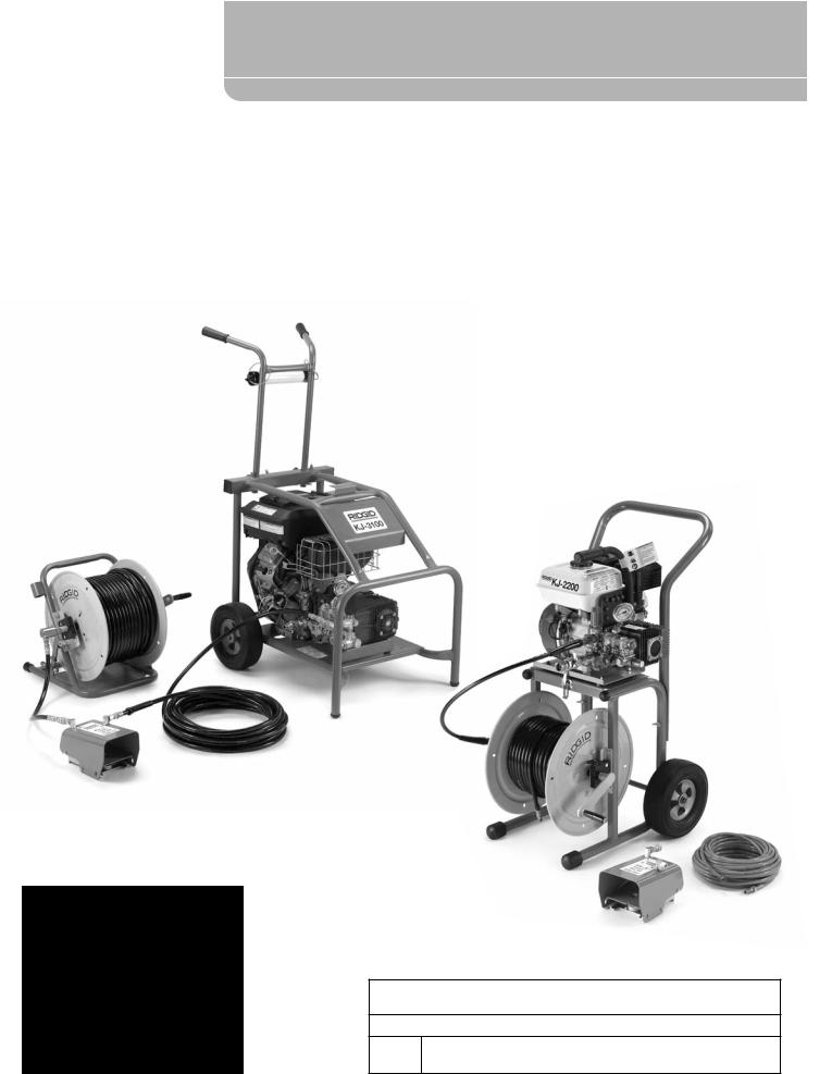
 Water Jetter
KJ-2200/KJ-3100
Water Jetting Machines
KJ-3100
 WARNING!
Read this Operator’s Manual carefully before using this tool. Failure to understand and follow the contents of this manual may result in electrical shock, fire and/or serious personal injury.
KJ-2200
KJ-2200/KJ-3100 Water Jetting Machines
Record Serial Number below and retain product serial number which is located on nameplate.
Serial
No.

KJ-2200/KJ-3100 Water Jetting Machines
Contents
Recording Form For Machine Serial Number........................................................................................................................................................... |
1 |
Safety Symbols......................................................................................................................................................................................................................... |
3 |
General Safety Rules.............................................................................................................................................................................................................. |
3 |
Work Area Safety............................................................................................................................................................................................................... |
3 |
Electrical Safety.................................................................................................................................................................................................................. |
3 |
Personal Safety................................................................................................................................................................................................................... |
3 |
Tool Use and Care............................................................................................................................................................................................................. |
3 |
Service.................................................................................................................................................................................................................................... |
4 |
Water Jetter Safety Warnings........................................................................................................................................................................................... |
4 |
Description, Specifications and Standard Equipment........................................................................................................................................ |
5 |
Description........................................................................................................................................................................................................................... |
5 |
Specifications...................................................................................................................................................................................................................... |
6 |
Icons........................................................................................................................................................................................................................................ |
6 |
Standard Equipment....................................................................................................................................................................................................... |
6 |
Machine Assembly.................................................................................................................................................................................................................. |
6 |
Engine Oil.............................................................................................................................................................................................................................. |
6 |
Pump/Gearbox Oil............................................................................................................................................................................................................ |
6 |
KJ-2200 Transport Cart................................................................................................................................................................................................... |
6 |
KJ-3100 Handle Assembly............................................................................................................................................................................................ |
6 |
Pre-Operation Inspection................................................................................................................................................................................................... |
7 |
Machine and Work Area Set-Up....................................................................................................................................................................................... |
8 |
Water Supply ...................................................................................................................................................................................................................... |
9 |
Drain Preparation........................................................................................................................................................................................................... |
10 |
Hose Set-Up...................................................................................................................................................................................................................... |
10 |
JETTER HOSE SELECTION CHART........................................................................................................................................................................... |
11 |
JETTER NOZZLE SELECTION CHART...................................................................................................................................................................... |
11 |
Operating Instructions...................................................................................................................................................................................................... |
12 |
Jetting the Drain............................................................................................................................................................................................................. |
13 |
Using the Pulse Mode.................................................................................................................................................................................................. |
14 |
Using Water Jetter Machine as a Pressure Washer.......................................................................................................................................... |
15 |
Pressure Washer Operation....................................................................................................................................................................................... |
15 |
Detergent Injector......................................................................................................................................................................................................... |
15 |
Maintenance Instructions................................................................................................................................................................................................ |
16 |
Cleaning............................................................................................................................................................................................................................. |
16 |
Engine................................................................................................................................................................................................................................. |
16 |
Pump Lubrication.......................................................................................................................................................................................................... |
16 |
Gearbox Lubrication..................................................................................................................................................................................................... |
16 |
Preparing Pump for Cold Weather Storage........................................................................................................................................................ |
16 |
Accessories............................................................................................................................................................................................................................... |
16 |
Troubleshooting................................................................................................................................................................................................................... |
18 |
Machine Storage................................................................................................................................................................................................................... |
18 |
Service And Repair.............................................................................................................................................................................................................. |
18 |
Disposal..................................................................................................................................................................................................................................... |
18 |
Lifetime Warranty................................................................................................................................................................................................ |
Back Cover |
* Original instructions - English
2

KJ-2200/KJ-3100 Water Jetting Machines
Safety Symbols
In this operator’s manual and on the product, safety symbols and signal words are used to communicate important safety information. This section is provided to improve understanding of these signal words and symbols.
This is the safety alert symbol. It is used to alert you to potential personal injury hazards. Obey all safety messages that follow this symbol to avoid possible injury or death.

 DANGER DANGER indicates a hazardous situation which, if not avoided, will result in death or serious injury.

 WARNING WARNING indicates a hazardous situation which, if not avoided, could result in death or serious injury.

 CAUTION CAUTION indicates a hazardous situation which, if not avoided, could result in minor or moderate injury.
NOTICE NOTICE indicates information that relates to the protection of property.
This symbol means read the operator’s manual carefully before using the equipment to reduce the risk of injury. The operator’s manual contains important information on the safe and proper operation of the equipment.
This symbol means always wear safety glasses with side shields or goggles when handling or using this equipment to reduce the risk of eye injury.
This symbol indicates the risk of high pressure water directed at body parts, causing skin puncture and injection injuries.
This symbol indicates the risk of the jetter hose whipping, and causing striking or injection injuries.
This symbol indicates the risk of breathing carbon monoxide and causing nausea, fainting or death.
This symbol indicates the risk of fire and explosion from gasoline or other sources causing burns and other injury.
General Safety Rules |
|
|
Personal Safety |
|||||
|
|
|
|
|
|
• |
Stay alert, watch what you are doing and use |
|
|
|
|
warning |
|
|
|
common sense when operating a power tool. |
|
Read and understand all instructions. Failure to fol- |
|
Do not use a tool while you are tired or under |
||||||
low all instructions listed below may result in elec- |
|
the influence of drugs, alcohol or medication. A |
||||||
tric shock, fire, and/or serious injury. |
|
|
|
moment of inattention while operating power tools |
||||
|
|
|
|
|
|
|
may result in serious personal injury. |
|
|
SAVE THESE INSTRUCTIONS! |
|
||||||
|
• |
Dress properly. Do not wear loose clothing or |
||||||
Work Area Safety |
|
|
||||||
|
|
|
jewelry. Contain long hair. Keep your hair, cloth- |
|||||
• |
Keep work area clean and well |
lit. Cluttered |
|
ing and gloves away from moving parts. Loose |
||||
|
clothes, jewelry or long hair can be caught in mov- |
|||||||
|
benches and dark areas invite accidents. |
|
||||||
|
|
ing parts. |
||||||
• |
Do not operate power tools in explosive atmo- |
|
||||||
• |
Do not overreach. Keep proper footing and bal- |
|||||||
|
spheres, such as in the presence of flammable |
|||||||
|
|
ance at all times. Proper footing and balance en- |
||||||
|
liquids, gases, or dust. Power tools create sparks |
|
||||||
|
|
ables better control of the tool in unexpected situ- |
||||||
|
which may ignite the dust or fumes. |
|
|
|
||||
|
|
|
|
ations. |
||||
• |
Keep bystanders, children, and visitors away |
|
||||||
• |
Use safety equipment. Always wear eye protec- |
|||||||
|
while operating a power tool. Distractions can |
|||||||
|
|
tion. Dust mask, non-skid safety shoes, hard hat, or |
||||||
|
cause you to lose control. |
|
|
|
||||
|
|
|
|
hearing protection must be used for appropriate |
||||
|
|
|
|
|
|
|
||
Electrical Safety |
|
|
|
conditions will reduce personal injuries. |
||||
|
|
|
|
|||||
• |
Avoid body contact with grounded surfaces such |
Tool Use and Care |
||||||
|
as pipes, radiators, ranges and |
refrigerators. |
• |
Donotforcethetool.Usethecorrecttoolforyour |
||||
|
There is an increased risk of electric shock if your |
|||||||
body is grounded. |
application. The correct tool will do the job better |
|
and safer at the rate for which it was designed. |
||
|
||
|
|
|
|
3 |

KJ-2200/KJ-3100 Water Jetting Machines
•Do not use the power tool if the switch does not turn it ON and OFF. Any tool that cannot be controlled with the switch is dangerous and must be repaired.
•Store idle tools out of the reach of children and other untrained persons. Tools are dangerous in the hands of untrained users.
•Maintain tools with care. Keep cutting tools sharp and clean. Properly maintained tools with sharp cutting edges are less likely to bind and are easier to control.
•Check for misalignment or binding of moving parts, breakage of parts and any other condition that may affect the tool’s operation. If damaged, have the tool serviced before using. Many accidents are caused by poorly maintained tools.
•Use only accessories that are recommended by the manufacturer for your model. Accessories that may be suitable for one tool, may become hazardous when used on another tool.
Service
•Tool service must be performed only by qualified repair personnel. Service or maintenance performed by unqualified personnel could result in a risk of injury.
•When servicing a tool, use only identical replacement parts. Follow instructions in the Maintenance section of this manual. Use of unauthorized parts or failure to follow Maintenance Instructions may create a risk of electrical shock or injury.
Water Jetter SafetyWarnings
 warning
This section contains important safety information that is specific to this tool.
Read these precautions carefully before using this Drain Cleaning Machine to reduce the risk of electrical shock or other serious personal injury.
SAVE ALL WARNINGS AND INSTRUCTIONS
FOR FUTURE REFERENCE!
Keep this manual with the machine for use by the operator.
•Never operate the jetter with the hose end outside of the drain. Hose can whip, causing striking injuries and spray can penetrate skin and cause serious injury.
•High pressure water can inject under skin resulting in serious injury including amputation. Do not direct spray at people or animals.
•Do not operate jetter above pressure rating or 140°F / 60°C (inlet water temperature). This increases the risk of injury, including burns, and damage to the jetter.
•Onepersonmustcontrolboththejettingprocess and the foot valve. Always use the foot valve. If the jetter hose comes out of the drain, the operator must be able to shut the water flow off to reduce the risk of the jetter hose whipping, causing striking and high pressure injection injuries.
•Always use appropriate personal protective equipment while handling and using drain cleaning equipment. Drain may contain chemicals, bacteria and other substances that may be toxic, infectious, cause burns or other issues. Appropriate personalprotectiveequipmentalwaysincludessafety glasses and gloves, and may also include equipment such as latex or rubber gloves, face shields, goggles, protective clothing, respirators, and steel toed footwear.
•Practice good hygiene. Use hot soapy water to wash hands and other body parts exposed to drain contents after handling or using drain cleaning equipment. Do not eat or smoke while operating or handling drain cleaning equipment. This will help prevent contamination with toxic or infectious material.
•Do not spray toxic or flammable liquids. This will reduce the risk of burns, fire, explosion or other injury.
•Gasoline and its vapors are highly flammable and explosive. See engine manual for precautions to reduce the risk of burns, explosions and serious injury while handling and using gasoline.
•Engines produce carbon monoxide, a colorless, odorless poison gas. Breathing carbon monoxide can cause nausea, fainting or death. Do not start and run engine in an enclosed area, even if doors and windows are open. Only operate outside.
•Hot surfaces can cause burns and fire. Keep body parts and flammable material away from hot surfaces.
•Read and understand this manual, the engine manual and the warnings and instructions for all equipment being used with this tool before operating. Failure to follow all warnings and instructions may result in property damage and/or serious injury.
The EC declaration of conformity (890-011-320.10) will accompany this manual as a separate booklet when required.
4
KJ-2200/KJ-3100 Water Jetting Machines
If you have any question concerning this RIDGID® product:
–Contact your local RIDGID distributor.
–Visit www.RIDGID.com or www.RIDGID.eu to find your local RIDGID contact point.
–Contact RIDGID Technical Services Department at rtctechservices@emerson.com, or in the U.S. and Canada call (800) 519-3456.
Description, Specifications and Standard Equipment
Description
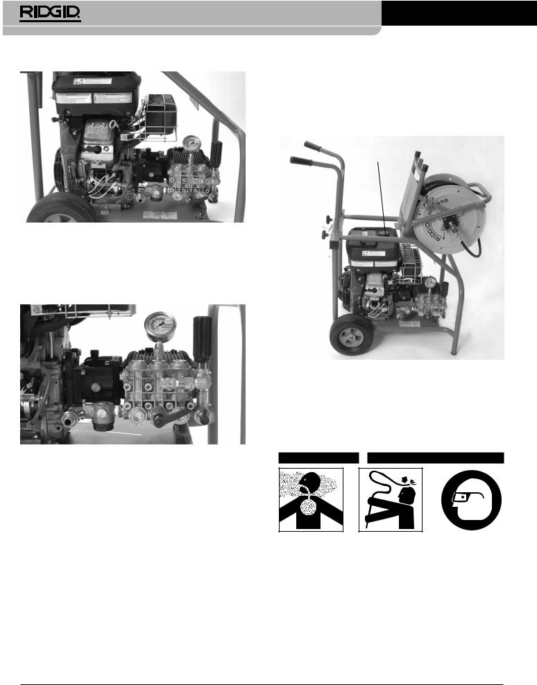
The RIDGID® Engine Powered Water Jetting Machines are portable high pressure water jetters designed to use a combination of water pressure and flow to clear grease, sludge, sediment and roots out of drains. A highly flexible and lightweight hose is propelled through the drain by the reverse jets on the jetter nozzle, and when retrieved scrubs the line flushing debris away. With the pulse activation engaged, difficult bends and traps are more easily negotiated. All machines are equipped with a gasoline engine to drive the triplex plunger pump.
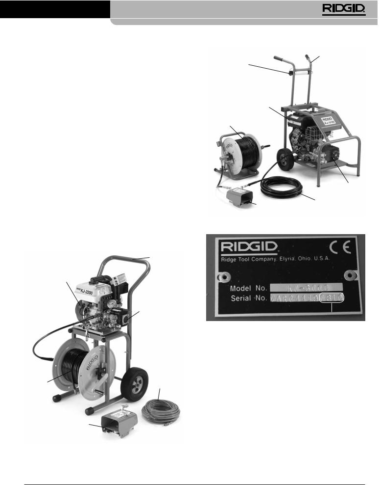
Handle
Engine Switch
Engine Pump
Handles
Manual Holder
Engine
Reel
Pump
Hose
Foot Switch
Figure 2 – KJ-3100 Water Jetting Machine
Date Code
Figure 3 – Machine Serial Number
The machine serial number is located on the frame. The last 4 digits indicate the month and year of the manufacture. (08 = month, 10 = year).
Hose
Reel
Foot Switch
Figure 1 – KJ-2200 Water Jetting Machine
5
KJ-2200/KJ-3100 Water Jetting Machines
Specifications |
Pump/Gearbox Oil |
Jetter |
Motor |
Pressure |
|
Model |
H.P. |
PSI / bar |
|
|
|||
KJ-2200 |
6.5 / 6,5 |
2200 / 150 |
|
KJ-3100 |
16 |
3000 / 205 |
|
|
|
|
|
Flow Rate |
Drain Line Capacity |
Weight (w/o Hose Reel) |
|
GPM / liter |
inch / mm |
lbs / kg |
|
2.4 / 9 |
11/4 - 6 / 32 - 152 |
65 |
/ 30 |
5.5 / 20 |
2 - 10 / 50 - 250 |
262 |
/ 119 |
|
|
|
|
Pump: Replace the plug in the top of the pump and replace with dipstick/breather cap. Operating the jetter with the plug in place could damage the pump seals. Check oil level per Maintenance Instruction section.
Gearbox (KJ-3100 only): Replace the plug in the top of the pump with dipstick/breather cap. Operating the jetter with the plug in place could damage the gearbox seals. Check lubricant level per the Maintenance Instruction section.
Icons
Pressure Mode
Pulse Mode
Standard Equipment
All Jetters come with
•Appropriate Jetter Nozzles
•Nozzle CleaningTool
•FV-1 FootValve
•Engine Operator’s Manual
See the RIDGID catalog for specific equipment supplied with each catalog number.
NOTICE This machine is made to clean drains. If properly used it will not damage a drain that is in good condition and properly designed, constructed and maintained. If the drain is in poor condition or not properly designed, constructed or maintained, the drain cleaning process may not be effective or could cause damage to the drain. The best way to determine the condition of a drain before cleaning is through visual inspection with a camera. Improper use of this jetting machine can damage the jetter and the drain. This machine may not clear all blockages.
Machine Assembly
 warning
To prevent serious injury during use and prevent machine damage, follow these procedures for proper assembly.
Engine Oil
NOTICE Jetter is shipped without oil in the engine. Operating the engine without oil will result in engine failure. Add oil prior to operation. See supplied engine operator’s manual for specific information on adding oil and oil selection.
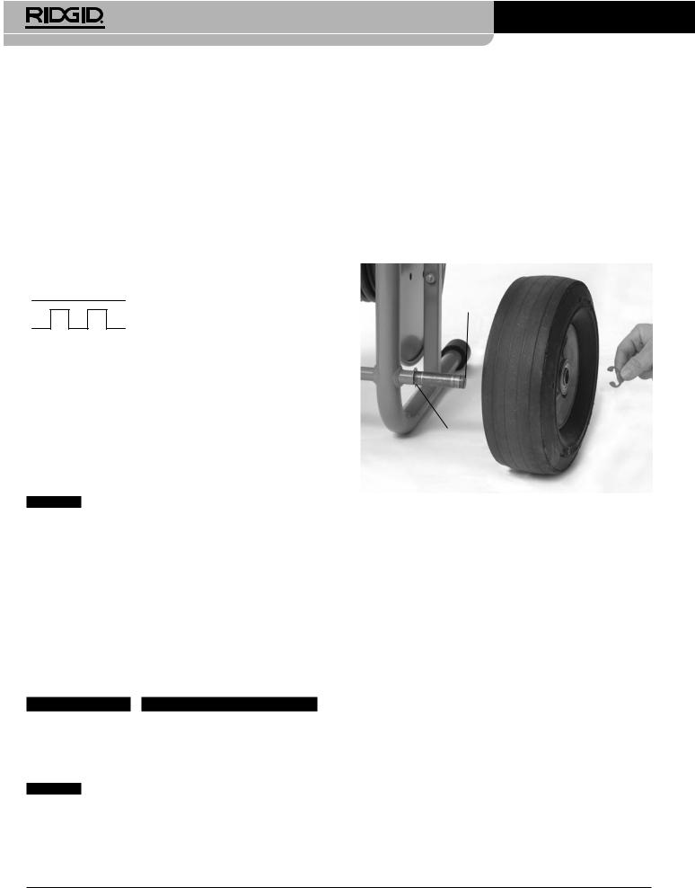
Outer Grove
Retaining Clip
Figure 4 – Assembly of the KJ-2200
KJ-2200 Transport Cart
1.Install retaining clip into inner groove on each end of axle. (See Figure 4.)
2.Slide a wheel over each end of axle.
3.Install retaining clip into outer groove on each end of axle to retain wheel.
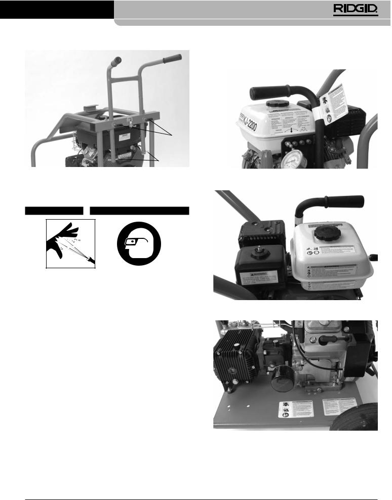
4.Use the supplied carriage bolts and wing nuts to attach the handle to the frame.
5.Lift the motor/pump assembly onto the cart, aligning the holes in the base plate with the pins in the top of thecart.Usethelatchesonthecarttoretainthemotor/ pump. Make sure the assembly is securely attached.
KJ-3100 Handle Assembly
1.Insert handle through the two holes in the rear cross bar of the frame. (See Figure 5.)
2.Insert a hairpin through the holes at the bottom of the handle to prevent the handle from pulling out.
3.Screw the T-knobs into the rear cross bar. Adjust the handles as desired and tighten the knobs to secure the handle.
6
KJ-2200/KJ-3100 Water Jetting Machines
T-Knobs
Insert Hair
Pin
Figure 5 – KJ-3100 Handle Assembly
Pre-Operation Inspection
 warning
Before each use, inspect your water jetter and correct any problems to reduce the risk of serious injury from high pressure water and other causes and prevent jetter damage.
Always wear safety glasses, glovesandother appropriate protective equipment when inspecting your jetter to protect against chemicals and bacteria on the equipment.
1.Make sure that the engine switch/key is in the OFF position.
2.Clean any oil, grease or dirt from the equipment, including the handles and controls. This aids inspection and helps prevent the machine or control from slipping from your grip.
3.Inspect the water jetter and accessories for the following:
•Proper assembly and completeness.
•Broken,worn,missing,mis-aligned,bindingorloose parts.
•Presence and readability of the warning labels.
(See Figure 6.)
•Any other condition which may prevent the safe and normal operation.
If any problems are found, do not use the water jetter until the problems are corrected.
Figure 6A – KJ-2200 Warning Labels
Figure 6B – KJ-2200 Warning Labels
Figure 6C – KJ-3100 Warning Labels
7
KJ-2200/KJ-3100 Water Jetting Machines
Figure 6D – KJ-3100 Warning Labels
4.Clean water inlet filter/filter washer.Unscrew cover from bottom of inlet filter for cleaning. Dirt and debris can restrict the water flow to the pump and cause performance issues.
Filter
Figure 7 – Inlet Filter/Filter Washer
5.Inspect the jetter nozzle orifices for any damage or blockage. Blockages can be cleaned with a nozzle cleaning tool. Use care not to enlarge nozzle orifices while cleaning. Damaged nozzles or nozzles with enlarged orifices can decrease jetter performance and should be replaced.
6.Inspect the hoses, connectors and fittings for wear and damage. If there are any kinks, cracks, breaks or wear through the outer jacket of the hose or other damage, do not use the hose. Damaged hoses can burst or leak high pressure water and cause serious injury. Replacement hoses and fitting should be rated at or higher than the jetter pressure.
7.Inspect and maintain the engine per the engine operator’s manual.
8.Check engine fuel level. For the KJ-3100, disconnect the hose reel latch and rotate the hose reel forward
until it rests on the frame to provide access to the engine gas cap Figure 8. If needed, add unleaded gasoline. See engine operator’s manual for details. Use caution when handling gasoline. Re-fuel in a well ventilated area. Do not overfill tank and do not spill fuel. Make sure tank cap is securely closed.
FuelTank Cap
Figure 8 – KJ-3100 FuelTank Access
9.Check the oil level in the pump and gear box (if equipped) and add oil if needed (see Maintenance Instructions section).
Machine andWork Area Set-Up
 warning
Always wear safety glasses, gloves and other appropriate protective equipment when setting up your jetter to protect against chemicals and bacteria on the equipment. Rubber soled, non-slip shoes can help prevent slipping on wet surfaces.
Engines produce carbon monoxide, a colorless, odorless poison gas. Breathing carbon monoxide can cause nausea, fainting or death. Do not start and run engine in an enclosed area, even if doors and windows are open. Only operate outside.
Set up the jetter and work area according to these procedures to reduce the risk of injury from high
8
KJ-2200/KJ-3100 Water Jetting Machines
pressure water, chemical burns, infections, carbon monoxide and other causes, and prevent jetter damage.
1.Check work area for:
•Adequate lighting.
•Flammableliquids,vaporsordustthatmayignite.
If present, do not work in area until sources have been identified and corrected. The jetter is not explosion proof and can cause sparks.
•Clear, level, stable dry place for machine and operator. If needed, remove the water from the work area. Wood or other coverings may need to be put down.
•Jetter location that is in a well ventilated outdoor area. Do not place the jetter indoors, even with doors and windows open. Jetter can be located remotely from the point of use.
•Suitable water supply.
•Clear path to transport the jetter to the set up location.
2.Inspect the drain to be cleaned. If possible, determine the access point(s) to the drain, the size(s) and length(s) of the drain, distance to tanks or mainlines, the nature of the blockage, presence of drain cleaning chemicals or other chemicals, etc. If chemicals are present in the drain, it is important to understand the specific safety measures required to work around those chemicals. Contact the chemical manufacturer for required information.
If needed, remove fixture (water closet, etc.) to allow access to the drain. Do not feed the hose through a fixture. This could damage the hose and the fixture.
3.Determine the correct equipment for the application. See the Specifications section for information on these jetters. Drain cleaners and jetters for other applications can be found by consulting the RIDGID Catalog, on line at www.RIDGID.com or www.RIDGID.eu .
4.Make sure all equipment has been properly inspected.
5.Evaluate the work area and determine if any barriers are needed to keep bystanders away. Bystanders can distract the operator. If working near traffic, erect cones or other barriers to alert drivers.
6.If needed, place protective covers in the work area. The drain cleaning process can be messy.
7.Takethejettertothewell-ventilatedoutdoorworkarea along the clear path. If the machine needs to be lifted, use proper lifting techniques. Use care moving equipment up and down stairs, and be aware of possible slip hazards. Wear appropriate footwear to help prevent slips.
Water Supply
Confirm that there is sufficient water flow for jetter. Run a hose from the water source to the jetter. Use the largest diameter, shortest length hose possible. A 3/4” / 19 mm I.D. hose is the minimum recommended size. An appropriate backflow prevention device should be used to comply with all local codes and ordinances. Turn the water on at the source and measure the time it takes to fill a clean five gallon / 18,9 liter bucket. See the following table for maximum bucket fill times for each jetter.
Jetter |
Rating |
Maximum 5 Gallon / 18,9 liter |
|
GPM / liter |
Bucket FillTime |
|
|
|
KJ-2200 |
2.4 / 9 |
125 seconds |
KJ-3100 |
5.5 / 20 |
55 seconds |
Insufficient water flow will prevent the jetter from reaching thepressureratingandcoulddamagethepump.Inspectthe water in the bucket for dirt and debris. Dirt and debris in the water supply can cause excess pump wear, clog the jetter filtersnozzlesandreduceperformance.Donotusewaterfrom ponds,lakesor othersources thatmaybe contaminated.
In cases of insufficient water flow, possible solutions include using fittings to allow multiple supply hoses to be connected to the jetter or the use of a tank.
If a tank is used, plumb a tee with full port valves to the jetter water inlet as shown in Figure 9. Connect a 3/4” / 19 mm hose no longer than 6 feet / 1,8 m to the valve on the outlet of the tee, and connect the water supply to the run of the tee. Either place the hose end in the tank or connect to the tank outlet. The entire length of the tank hose should be no more than 5” / 12,7 cm above the jetter water inlet, or the jetter will not draw water from the tank.
Water InTo Jetter
Inlet Filter
Tee
HoseToTank
Full PortValve
Water Supply In
Figure 9 – Water Supply Connections When Using ATank
9
KJ-2200/KJ-3100 Water Jetting Machines
Fill the tank prior to starting the jetter. When starting jetter, turn the tank valve off. As soon as the jetter is started, open the tank valve. Monitor the tank water level, and if needed, stop jetting to allow the tank to refill. Do not allow the water level to fall below the hose end.
Hot water can be used for improved cleaning. Do not use water hotter than 140°F / 60°C – this can cause the pump thermal overload to open. When using hot water, use appropriate personal protective equipment to reduce the risk of burns.
When using in cold weather, use precautions to prevent water from freezing in the pump. This can damage the pump.
Make sure that the inlet supply valve on the jetter is closed and attach the supply hose to the jetter.
Drain Preparation
If working through a manhole, storm grate or other large access, use pipe and fittings to create a guide for the jetter hose from the drain opening to operation point. This will prevent the jetter hose from whipping around in the access and protect the hose from damage.
1.Select a jetter hose size appropriate for the drain being cleaned. It is not generally recommended to connect two jetter hoses together for cleaning drains. The connection between the two hoses is less flexible and can prevent passage through fittings See Jetter Hose Selection Chart.
2.As needed, separate the hose reel from the motor/ pump assembly. Locate the hose reel within 3 feet / 90 cm of the drain opening. Do not allow excessive amounts of hose outside of the drain to prevent hose damage. If the hose reel cannot be placed within 3 feet / 90 cm of the drain opening, extend the drain opening back to the hose reel with similar sized pipe and fittings.
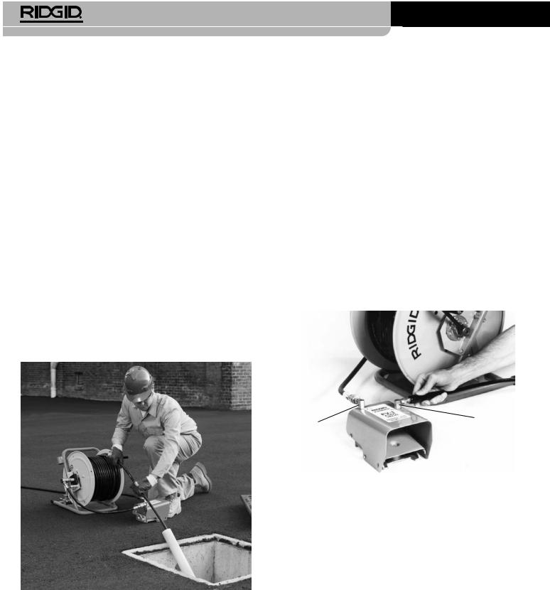
3.Route a hose from the jetter to the IN fitting on the foot valve. Use teflon tape to seal the connection. Position the foot valve for accessibility. You must be able to control the jetter hose and the foot valve.
4.Connect the hose from the reel to the OUT fitting on the foot valve.
Out Fitting |
In Fitting |
|
|
Figure 11 – Foot Valve Connection |
|
|
5. |
Mark the jetter hose near the end to indicate when |
|
|
the nozzle is getting close to the drain opening |
|
|
when withdrawn. This will help prevent the nozzle |
|
|
from coming out of the drain and whipping around. |
|
|
The distance depends on the configuration of the |
|
|
drain, but should be at least 4’/ 1,2 m. |
|
6. |
Remove the nozzle from the end of the jetter hose |
|
|
and place the end of the jetter hose in the drain. |
Figure 10 – Extending the Drain Opening to the Operation |
|
Open the inlet supply valve to purge the air and any |
|
debris from the jetter and hoses. Allow water to flow |
|
Point |
|
for at least 2 minutes. |
Hose Set-Up |
7. |
Close the inlet supply valve. |
Use care when routing jetter hoses. Routing hoses over |
8. |
Select a nozzle. Use nozzles specifically sized for the |
rough surfaces, sharp edges, crossing hoses, etc. can |
|
jetter being used. Using incorrect nozzles can cause |
damage the hose jacket, especially when the jetter is |
|
poor performance (low operating pressure or low |
used in the pulse mode. Keeping the jetter hose on the |
|
flow) or may damage the jetter with excessively high |
reel will help to minimize hose damage. |
|
|
|
|
|
10 |
|
|
KJ-2200/KJ-3100 Water Jetting Machines
pressures. Make sure the nozzle orifices are clear and open. See Jetter Nozzle Selection Chart.
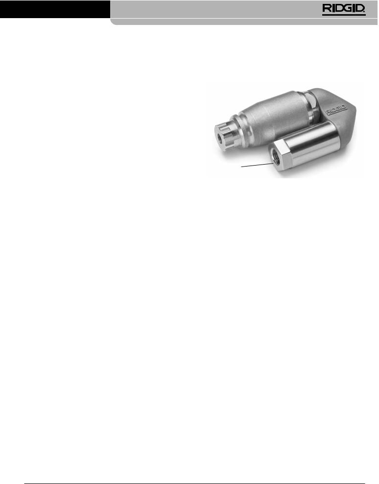
If using the RR3000 nozzle for drains larger than 6”/ 152 mm and up to 9”/ 229 mm, the extension must be used. For drains 6” / 152 mm and smaller, no extension is needed. If needed, firmly hand tighten the extension to the RR3000 – do not over tighten. Using the RR3000 nozzle in a line larger than 6”and up to 9”/ 152 mm and up to 229 mm without an extension, or in lines larger than 9” / 229 mm may allow the nozzle to change direction in the drain, exit at the user and cause serious injury (Figure 12).
9.Firmlyhandtightenthenozzletotheendofthehose– do not over tighten. Over tightening the nozzle can damage the nozzle and cause poor performance.
JETTER HOSE SELECTION CHART
10. Insert the hose with nozzle attached into the drain and open the inlet supply valve. Confirm that water flows freely through the nozzle and close the inlet supply valve.
Extension
Figure 12 – RR3000 Nozzle with Extension
|
|
Pipe Size |
Nozzle Size |
Hose Size (ID) |
Hose Size (OD) |
|||||
|
Applications |
inch / mm |
inch / mm |
inch / mm |
inch / mm |
|||||
|
Bathroom sinks, urinals, and small lines. |
11/4 - 2 / 32 - 50 |
1/8 / 3,2 NPT |
1/8 / 3,2 |
3/16 / 4,8 |
|||||
-KJ2200 |
Kitchen sinks, laundry tubs and stacks, clean-outs, and |
2 - 3 / 50 |
- 76 |
1/8 / 3,2 NPT |
3/16 / 4,8 |
1/4 / 6,4 |
||||
Shower and floor drains, lateral lines, and grease traps. |
3 - 4 |
/ 76 - 101 |
1/4 / 6,4 NPT |
1/4 / 6,4 |
1/2 / 13 |
|||||
|
vents. |
|
|
|
|
|
|
|
|
|
|
|
|
|
|
|
|
||||
|
Lateral and main lines. |
4 - 6 / 101 |
- 152 |
1/4 / 6,4 NPT |
1/4 / 6,4 |
1/2 / 13 |
||||
KJ-3100 |
Stacks, clean-outs and vents. |
2 - 3 / 50 |
- 76 |
1/8 / 3,2 NPT |
3/16 / 4,8 |
1/4 / 6,4 |
||||
Lateral and main lines. |
4 - 10 |
/ 101 - 250 |
1/4 |
/ 6,4 NPT |
3/8 |
/ 9,5 |
5/8 |
/ 16 |
||
|
Floor drains, lateral lines, and grease traps. |
3 - 4 |
/ 76 - 101 |
1/4 |
/ 6,4 NPT |
3/8 |
/ 9,5 |
5/8 |
/ 16 |
|
|
|
|
|
|
|
|
|
|
|
|
JETTER NOZZLE SELECTION CHART
|
Thread Size, inch / mm |
1/8 / 3,2 NPT |
1/4 / 6,4 NPT |
|
|
Hose Size (Inside Diameter), inch / mm |
1/8 & 3/16 / 3,2 & 4,8 |
1/4 / 6,4 |
|
|
Hose Size (Outside Diameter), inch / mm |
3/16 & 1/4 / 4,8 & 6,4 |
1/2 / 13 |
|
KJ-2200 |
Features three reverse jet thrusts for maximum propulsion to jet long distances. Use this nozzle |
H-61 |
H-71 |
|
for most applications. |
||||
|
|
|||
Usesthreejetthrustersinreverseplusonejetpointedforwardtopenetratesolidgreaseorsludge |
H-62 |
H-72 |
||
|
blockages. The forward jet blasts a small hole in the blockage for the nozzle to follow. It is also |
|||
|
very effective when jetting ice blockages. |
|
|
|
|
Use the drop head to help negotiate difficult bends.This nozzle has three reverse jet thrusts. |
H-64 |
|
|
|
Use the spinning nozzle to clean grease and similar blockage from drain. |
H-65 |
H-75 |
11
KJ-2200/KJ-3100 Water Jetting Machines
|
Thread Size, inch / mm |
1/8 / 3,2 NPT |
1/4 / 6,4 NPT |
|
|
Hose Size (Inside Diameter), inch / mm |
3/16 / 4,8 |
3/8 / 9,5 |
|
|
Hose Size (Outside Diameter), inch / mm |
1/4 / 6,4 |
5/8 / 16 |
|
|
Features four (4) reverse jet thrusts for maximum propulsion to jet long distances. Use this nozzle |
H-101 |
H-111 |
|
KJ-3100 |
for most applications. |
|||
|
|
|||
Usesthreejetthrustersinreverseplusonejetpointedforwardtopenetratesolidgreaseorsludge |
H-102 |
H-112 |
||
blockages. The forward jet blasts a small hole in the blockage for the nozzle to follow. It is also |
||||
very effective when jetting ice blockages. |
|
|
||
|
|
|
||
|
Use the drop head to help negotiate difficult bends.This nozzle has four (4) reverse jet thrusts. |
H-104 |
|
|
|
Use the spinning nozzle to help clean grease and similar blockage from drain. |
H-105 |
H-115 |
|
|
Use to clear roots and other type of blockages. |
|
RR3000 |
|
|
NOTE! Use extension to stabilize the RR3000 when cleaning 8” / 200 mm diameter drains. |
|
||
|
|
|
Operating Instructions
 warning
Always wear eye protection to protect your eyes against dirt and other foreign objects. Always wear appropriate personal protective equipment for the work environment.
Never operate the jetter with the hose end outside of the drain. Hose can whip, causing striking injuries and spray can penetrate skin and cause serious injury.
High pressure fluid can inject under skin resulting in serious injury, including amputation. Do not direct spray at people or animals.
Do not operate jetter above pressure rating or 140°F / 60°C (inlet water temperature). This increases the risk of injury, including burns, and damage to the jetter.
One person must control both the jetting process and the foot valve. Always use the foot valve. If the jetter hose comes out of the drain, the operator must be able to shut the water flow off to reduce the risk of the jetter hose whipping, causing striking and high pressure injection injuries.
Always use appropriate personal protective equipment while handling and using drain cleaning equipment. Drain may contain chemicals, bacteria and other substances that may be toxic, infectious, cause burns or other issues. Appropriate personal protective equipment always includes safety glasses and gloves, and may also include equipment such as latex or rubber gloves, face shields, goggles, protective clothing, respirators, and steel toed footwear.
Follow operating instructions to reduce the risk of injury from whipping hoses, high pressure liquid injection, carbon monoxide and other causes.
1.Make sure that machine and work area is properly set up and that the work area is free of bystanders and other distractions. If the jetter is located remotely from the point of use, another person should be located at the jetter.
2.Insert the hose with nozzle attached into the drain at least three feet so that the end of the hose will not come out of the drain and whip around when the machine is started.
3.Confirm that the pulse actuator lever is rotated counter-clockwise in the “Pressure” position (Figure 16).
4.Open the inlet supply valve. Never start the engine without the water supply turned ON. This can damage the pump.
5.Press the foot valve to reduce pressure and allow the engine to start. Confirm that water flows freely through the nozzle. Following the starting instructions supplied in the engine manual, start the engine. Allow the engine to warm up.
12
KJ-2200/KJ-3100 Water Jetting Machines
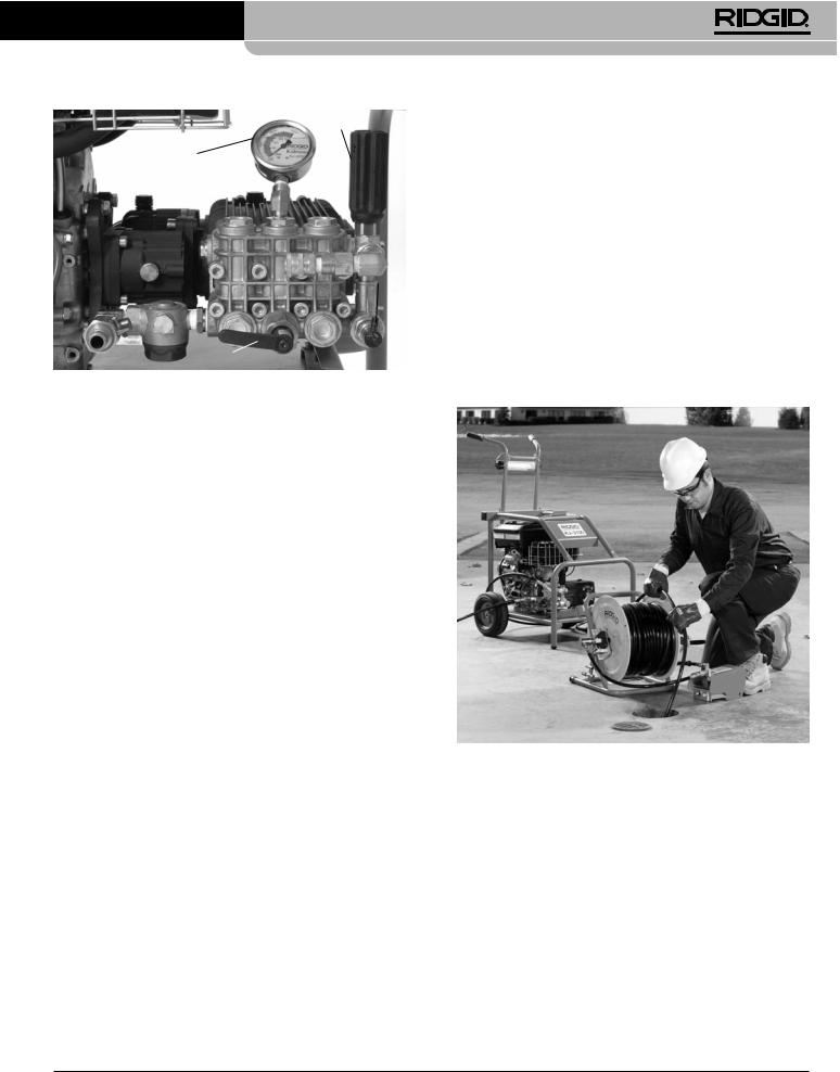
UnloaderValve
Pressure Gauge
Thermal
Overload
Pulse Actuator
Figure 13 – Controls
6. Turn the unloader valve while monitoring the pressure gauge to adjust the pressure as desired (clockwise to increase pressure, counter-clockwise to decreasepressure).Donotexceedthemachinepressure rating being used. Do not force the unloader valve or use wrenches or tools to turn. This will damage the unloader valve.
Jetter |
Pressure Rating, PSI / bar |
|
|
KJ-2200 |
2200 / 150 |
KJ-3100 |
3000 / 205 |
If the jetter will not generate the rated pressure or is erratic:
• Make sure the engine throttle is properly adjusted.
• Make sure that the inlet supply valve is fully open and other valves in the supply system are fully open.
• Turn unloader valve clockwise to increase pressure. Do not force.
•Run the jetter without a nozzle on the hose to remove air or debris from the system. Turn the jetter OFF before removing or attaching the nozzle.
7.Assume a proper operating position.
•Be sure you can control the ON/OFF action of the foot valve. Do not press the foot valve yet.
•Be sure that you have good balance and do not have to overreach.
•You must be able to place one hand on the jetter hose at all times to control and support the hose.
•You must be able to reach the reel for coiling the hose.
This operating position will help to maintain control of the jetter hose.
Figure 14 – Proper Operating Position
•Make sure the pulse actuator is on the“Pressure” setting.
•Cycle the pulse actuator between the “Pressure” and“Pulse”position several times while the unit is running to clear any trapped air from the system.
•Inspect system for leaks. Use caution during inspection to prevent injury. If leaks are found, shut jetter OFF before fixing.
•Turn the jetter OFF. Check the inlet filter/filter washer and make sure that they clear of debris.
•Make sure there is adequate water flow to the jetter.
•TurnthejetterandinletsupplyvalveOFF.Remove the nozzle and clean the orifices with the nozzle cleaning tool.
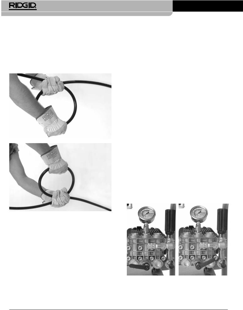
Jetting the Drain
When jetting a drain, typically the hose is fed into the drain the full distance to be cleaned and slowly pulled back. This allows the high pressure water directed at the drain walls to remove build-up.
Release the locking pin on the hose reel. With at least three feet of hose in the drain and one hand on the hose to control its movement, depress the foot valve. The reverse jet thrusters on the nozzle will help pull the hose into the drain. Feed the hose in the as far as needs to be cleaned. If the hose stops, it has encountered some type of obstruction.
If the nozzle cannot pass through an obstruction, such as a change in direction (trap, turn, etc.) or a blockage.
13
KJ-2200/KJ-3100 Water Jetting Machines
•Use sharp thrusts of the hose.
•Rotatethehoseaquartertohalfturntoorientthe set of the hose to the direction change (If the hose is rotated, once through the obstruction, turn the hose back to help prevent kinks) See Figure 15.
•Use the pulse mode. 

 (see next section).
•Use a trap hose or smaller diameter hose.
Figure 15 – Rotating the Hose
Once past a blockage, take the time to clean that section of drain prior to moving forward. Move several feet past the area of the obstruction and slowly pull the nozzle back through the area of the obstruction. Do this several times and then move further into the drain.
Watch the drain water level. If the water level gets too high, you may need to turn the jetter OFF and allow the water to drain prior to continuing. Jetting when the line is full of water is less effective than when the line is empty. Do not allow the jetter to run for extended period of time with the foot valve OFF. When the foot valve is OFF, water recirculates in the pump and cause the water to heat up. This can cause the pump thermal overload to open.
Once the nozzle is the desired distance into the drain, slowly (1 ft / 30 cm per minute for heavy drain accumulations) pull the nozzle back through the drain. Use one hand to control the hose and the other to wind the hose onto the reel. Watch as the nozzle gets closer to the drain opening that the nozzle does not come out of the drain while water is flowing. This could allow the hose to whip around and cause striking and high pressure fluid injuries. Always control the hose. Look for the mark on the hose near the nozzle. Release the foot valve to shut off the water flow.
Turn OFF the engine as directed in the engine manual, and depress the foot valve to release the system pressure. Never leave the system pressurized. If needed, change the nozzle and continue cleaning following the above process. Several passes through a line are recommended for complete cleaning.
When finished, with the jetter shut off, remove the nozzle and open inlet supply valve to flush out the pump and hose. If using the jetter in cold weather conditions, immediately drain the water from the system to help prevent damage from freezing. See Machine Storage for information on freeze protecting.
Using the Pulse Mode
When manipulating the hose is not enough to pass through a direction change or obstruction, the pulse mode should be used. The pulse mode induces large variation in water pressure that causes the hose to vibrate, easing hose advancement.
1.Turn the pulse actuator lever clockwise to the“Pulse” position. In pulse mode, the pressure gauge will read less than full pressure. This is normal.
PRESSURE |
|
|
PULSE |
|
||
|
|
|
|
|
|
|
|
|
|
|
|
|
|
|
|
|
|
|
|
|
Figure 16 – Pulse Actuator Lever Position
14

KJ-2200/KJ-3100 Water Jetting Machines
2.If needed, use sharp thrusts of the hose and hose rotation to help the nozzle through the obstruction.
3.Once through the obstruction, turn the pulse actuator lever counter-clockwise to the “Pressure” position. Do not leave the jetter in pulse mode any longer than needed to pass through an obstruction. Excessive use of the pulse feature can cause premature wear on hoses and system.
Using Water Jetter Machine as a Pressure Washer
The RIDGID water jetting machines can also be used as pressure washers with the addition of the pressure wash package. Use as a pressure washer is similar to use as a jetter, and those instructions should be used in conjunction with the following.
1.Locate an appropriate work area.
2.Make sure all equipment has been properly inspected.
3.Attach the wash wand to the wash wand hose. Al ways use hose with a pressure rating at least as high as the jetter pressure rating. Use a thread sealant to prevent leaks.
4.Attach hose to the jetter outlet. Make sure the ends of the hose are securely connected to prevent them from coming off under pressure.
5.Connect an appropriate water supply, as discussed earlier, to the jetter.
6.Open the inlet supply valve and squeeze the wash wand trigger to allow water to flow and purge any air from the system. Never start the engine without the water supply turned ON. This can damage the pump.
7.Make sure that pulse actuator lever is rotated coun- ter-clockwise in the“Pressure”position.
8.Wash Wand Nozzle Adjustments – By rotating the nozzle, the wash pattern can be adjusted from a fine stream to a wide fan type spray. By pulling the nozzle forward (low pressure) and backward (high pressure), the pressure can be adjusted. Make sure that the nozzle is pulled back to the high pressure position to start operation.
Low |
High |
|
Pressure |
||
Pressure |
||
|
||
|
Pattern Adjustment |
Lock Out
Figure 17 – Wash Wand Nozzle Adjustments
9.Wash Wand Lock Out – the wash wand includes a lock out on the back of the trigger. Flip the lock out down to prevent the operation of the trigger when the wash wand is not in use.
10. With the wand pointed in a safe direction, squeeze the wash wand trigger to reduce pressure and allow the engine to be started. Following the starting instructions supplied in the engine manual, start the engine. Allow the engine to warm up. Release the trigger as soon as the engine starts.
11. With the wand pointed in a safe direction, squeeze the wash wand trigger. Turn the unloader valve while monitoring the pressure gauge to adjust the pressure as desired. Do not exceed the machine pressure rating. Release the wash wand trigger.
Pressure Washer Operation
1.When using as a pressure washer use both hands to grip and direct the wash wand for greater control. Never direct the wash wand at people. High pressure fluid can inject under skin resulting in serious injury. Never direct wash wand at electrical equipment or wiring to reduce the risk of electrical shock.
2.Control the flow of water with the trigger. Use care when using the pressure washer. Holding the nozzle too close to a surface can damage it. Test a small, inconspicuous area to confirm the settings work as desired.
3.Do not allow the jetter to run for extended period of time with the trigger OFF. When the trigger is OFF, water recirculates in the pump and it causes the water to heat up. This can cause the pump thermal overload to open.
4.Once pressure washing is complete, release the trigger and turn OFF the engine as directed in the engine manual. Squeeze the trigger to release system pressure. Never leave the system pressurized.
Detergent Injector
1.If needed, attach the detergent injector to the outlet port. Remove the output hose and attach the detergent injector with arrow on the unit pointing the same direction as the water flow. Use thread sealant to prevent leaks. Reattach the output hose.
2.Attach the siphon hose to the detergent injector. Place the strainer end of hose into the detergent container. Only use detergents designed for use with pressure washers. Follow all detergent instructions. Do not spray flammable liquids or toxic chemicals. Other detergents, solvents, cleaners, etc. can damage the jetter, or cause serious injury.
15

KJ-2200/KJ-3100 Water Jetting Machines
3.When pressure washing, detergents are only dispensed when wash wand nozzle is in the low pressure position. Pull the nozzle forward to the low pressure position to dispense detergent.
4.During operation, the detergent application rate can be adjusted by turning the sleeve on the detergent injector. Counter-clockwise increases the amount of detergent, clockwise decreases.
5.When detergent application is complete, remove the strainer from the detergent, place into a bucket of clean water and flush the system of any detergent.
Maintenance Instructions
 warning
Before performing any maintenance, engine switch should be in OFF position and spark plug wires should be disconnected to prevent inadvertent operation. Press foot valve or wand trigger to release any fluid pressure in system.
Always wear safety glasses and gloves when performing any maintenance to help protect against drain chemicals and bacteria.
Cleaning
The hose should be cleaned as needed with hot, soapy water and/or disinfectants. Do not allow water to enter the engine or electrical system. Do not clean with pressure washer. Wipe the unit down with a damp cloth.
Engine
Maintain the engine as directed in the engine operator’s manual supplied with the unit.
Pump Lubrication
Check the pump oil level prior to use. Place the jetter on a level surface. Wipe any dirt and debris from the area of the dipstick and remove the dipstick – check the oil level. If needed, add SAE 30W non-detergent oil. Do not overfill. Reinstall dipstick.
Change oil in pump after first 50 hours of operation and every 500 hours of operation after that. With the pump warm from operation, remove plug on bottom of pump and drain oil into suitable container. Replace plug. Fill with approximately 32 oz / 0,9 kg of SAE 30W non-detergent oil using the checking procedure.
Gearbox Lubrication
Check the gearbox oil level prior to use. Place the jetter on a level surface. Wipe any dirt and debris from the
area of the dipstick and remove the dipstick – check the oil level. If needed, add SAE 90W gear lubricant. Do not overfill. Reinstall dipstick.
Change oil in gearbox every 500 hours of operation. With the gearbox warm from operation, remove plug on bottom of gearbox and drain oil into suitable container. Replace plug. Fill with approximately 8 oz / 0,2 kg of SAE 90W gear lubricant oil using the checking procedure.
Preparing Pump for Cold Weather Storage
NOTICE If the jetter will be stored under conditions where the temperature is near or below 32°F / 0°C, the jetter must be properly prepared. If water freezes in the pump, it can damage it.
There are two methods for preparing the jetter for cold weather storage. The first is to open all valves in the system and use compressed air to force any water out of the system. This can also be used to remove water from the hoses.
The second method uses RV antifreeze (non-ethylene glycol antifreeze). Do not use ethylene glycol antifreeze in the jetter pump. Ethylene glycol cannot be used in drainage systems.
1.Attach a 3’/ 90 cm section of hose to the inlet supply valve and open valve.
2.Place the end of the hose into the container of RV antifreeze.
3.Remove the nozzle from the end of the hose.
4.Start the jetter and run until antifreeze comes out of the end of the hose.
Accessories
 warning
To reduce the risk of serious injury, only use accessories specifically designed and recommended for use with the RIDGID Water Jetter Machines, such as those listed below. Other accessories suitable for use with other tools may be hazardous when used with RIDGID Water Jetter Machines.
16

KJ-2200/KJ-3100 Water Jetting Machines
KJ-2200 Jetter Nozzle and Hoses
Catalog |
Model |
|
|
Hose I.D. |
Hose O.D. |
||
|
|
|
|
|
|
||
No. |
No. |
Description |
|
inch / mm |
inch / mm |
||
64772 |
H-61 |
Propulsion Nozzle |
1/8 “/ 3,2 mm |
|
|
|
|
NPT |
|
|
|
|
|||
|
|
|
|
|
|
|
|
64777 |
H-62 |
Penetrating Nozzle |
Fits 1/4 “/ |
|
|
|
|
6,4 mm Hose |
|
|
|
|
|||
|
|
|
|
|
|
|
|
64782 |
H-64 |
Drop Head Nozzle |
|
|
|
|
|
82842 |
H-65 |
Spin Nozzle 2200 |
|
|
|
|
|
64787 |
H-71 |
Propulsion Nozzle |
1/4 “/ 6,4 mm |
|
|
|
|
NPT |
|
|
|
|
|||
|
|
|
|
|
|
|
|
64792 |
H-72 |
Penetrating Nozzle |
Fits 1/2 “/ |
|
|
|
|
13 mm Hose |
|
|
|
|
|||
|
|
|
|
|
|
|
|
82852 |
H-75 |
Spin Nozzle 2200 |
|
|
|
|
|
47592 |
H-1425 |
1/4”x 25’/ 6,4 mm x 7,6 m |
3/16 / 4,8 |
1/4 / 6,4 |
|||
47597 |
H-1435 |
1/4”x 35’/ 6,4 mm x 10,7 m |
3/16 / 4,8 |
1/4 / 6,4 |
|||
47602 |
H-1450 |
1/4”x 50’/ |
1/4” / 6,4 mm |
3/16 / 4,8 |
1/4 / 6,4 |
||
|
|
6,4 mm x 15,2 m |
Trap Hose |
|
|
|
|
49272 |
H-1475 |
1/4”x 75’/ |
Orange |
3/16 / 4,8 |
1/4 / 6,4 |
||
|
|
6,4 mm x 22,9 m |
|
|
|
|
|
49277 |
H-1400 |
1/4”x 100’/ |
|
3/16 / 4,8 |
1/4 / 6,4 |
||
|
|
6,4 mm x 30,5 m |
|
|
|
|
|
64732 |
H-1415 |
1/4”x 150’/ |
|
3/16 / 4,8 |
1/4 / 6,4 |
||
|
|
6,4 mm x 45,7 m |
|
|
|
|
|
|
|
Flexible Leader, |
|
1 |
|
3 |
|
50002 |
HL-1 |
1/4”/ 6,4 mm |
|
/8 |
/ 3,2 |
/16 |
/ 4,8 |
|
|
Flexible Leader, |
|
1 |
|
3 |
|
50007 |
HL-2 |
1/2”/ 13 mm |
|
/8 |
/ 3,2 |
/16 |
/ 4,8 |
47607 |
H-1250 |
1/2”x 50’/ |
|
1/4 / 6,4 |
1/2 / 13 |
||
|
|
13 mm x 15,2 m |
|
|
|
|
|
47612 |
H-1275 |
1/2”x 75’/ |
|
1/4 / 6,4 |
1/2 / 13 |
||
|
|
13 mm x 22,9 m |
|
|
|
|
|
47617 |
H-1200 |
1/2”x 100’/ |
|
1/4 / 6,4 |
1/2 / 13 |
||
|
|
13 mm x 30,5 m |
|
|
|
|
|
51587 |
H-1211 |
1/2”x 110’/ |
1/2”/ 13 mm |
1/4 / 6,4 |
1/2 / 13 |
||
|
|
13 mm x 33,5 m |
Jet Hose |
|
|
|
|
49487 |
H-1215 |
1/2”x 150’/ |
Black |
1/4 / 6,4 |
1/2 / 13 |
||
|
|
13 mm x 45,7 m |
|
|
|
|
|
51597 |
H-1220 |
1/2”x 200’/ |
|
1/4 / 6,4 |
1/2 / 13 |
||
|
|
13 mm x 61 m |
|
|
|
|
|
KJ-2200 Jetter Accessories
Catalog |
Model |
|
No. |
No. |
Description |
62882 |
H-5 |
Mini Hose Reel (No Hose included) |
64737 |
H-30 |
H-30 Cart with Hose Reel |
62877 |
H-30 |
H-30 Cart with Hose Reel and |
WH |
110’/ 33,5 m x 1/2”/ 13 mm Jet Hose |
|
64077 |
HP-22 |
Pressure Wash Package, KJ-2200 |
64767 |
HW-22 |
Wash Wand, KJ-2200 |
51572 |
H-1235 |
Wash Wand Hose 1/2”/ 13 mm x 35’/ 10,7 m |
48157 |
FV-1 |
Foot Valve |
66732 |
HF-4 |
Quick Connect Hose |
48367 |
H-25 |
Winterizing Kit |
47542 |
H-21 |
Nozzle Cleaning Tool |
67187 |
H-32 |
Jet Vac |
KJ-3100 Jetter Nozzles and Hoses
Catalog |
Model |
|
|
Hose I.D. |
Hose O.D. |
|
|
|
|
||
No. |
No. |
Description |
|
inch / mm |
inch / mm |
38698 |
H-101 |
Propulsion Nozzle |
1/8”/ 3,2 mm |
|
|
NPT |
|
|
|||
|
|
|
|
|
|
38713 |
H-102 |
Penetrating Nozzle |
Fits 1/4”/ |
|
|
6,4 mm Hose |
|
|
|||
38703 |
H-104 |
Drop Head Nozzle |
|
|
|
38723 |
H-105 |
1/8”/ 3,2 mm NPT Spin Nozzle |
|
|
|
38693 |
H-111 |
Propulsion Nozzle |
1/4”/ 6,4 mm |
|
|
NPT |
|
|
|||
|
|
|
|
|
|
38708 |
H-112 |
Penetrating Nozzle |
Fits 3/8”/ |
|
|
9,5 mm Hose |
|
|
|||
38718 |
H-115S |
1/4”/ 6,4 mm NPT Spin Nozzle |
|
|
|
16713 |
RR3000 |
Root Ranger Nozzle |
|
|
|
47592 |
H-1425 |
1/4”/ 6,4 mm x 25’/ 7,6 m Trap Hose |
3/16 / 4,8 |
1/4 / 6,4 |
|
|
|
1/4”/ 6,4 mm x |
1 |
|
|
47597 |
H-1435 |
35’/ 10,7 m |
/4”/ 6,4 mm |
3/16 / 4,8 |
1/4 / 6,4 |
|
|
Trap Hose |
Trap Hose |
|
|
|
|
|
|
|
|
47602 |
H-1450 |
1/4”/ 6,4 mm x |
|
3/16 / 4,8 |
1/4 / 6,4 |
50’/ 15,2 m |
Orange |
||||
|
|
Trap Hose |
|
|
|
49272 |
H-1475 |
1/4”/ 6,4 mm x 75’/ 22,9 m |
3/16 / 4,8 |
1/4 / 6,4 |
|
|
|
Trap Hose |
|
|
|
49277 |
H-1400 |
1/4”/ 6,4 mm x 100’/ 30,5 m |
3/16 / 4,8 |
1/4 / 6,4 |
|
|
|
Trap Hose |
|
|
|
64732 |
H-1415 |
1/4”/ 6,4 mm x 150’/ 45,7 m |
3/16 / 4,8 |
1/4 / 6,4 |
|
|
|
Trap Hose |
|
|
|
64827 |
H-3835 |
3/8”/ 9,5 mm ID x 35’/ 10,7 m |
3/8 / 9,5 |
5/8”/ 16 |
|
|
|
Wash Hose |
|
|
|
64832 |
H-3850 |
3/8”/ 9,5 mm ID x 50’/ 15,2 m |
3/8 / 9,5 |
5/8”/ 16 |
|
|
|
Jet/Wash Hose |
|
|
|
64837 |
H-3810 |
3/8”/ 9,5 mm ID x |
3 |
3/8 / 9,5 |
5/8”/ 16 |
100’/ 30,5 m |
/8”/ 9,5 mm |
||||
|
|
Jet Hose |
Jet Hose |
|
|
|
|
|
|
|
|
64842 |
H-3815 |
3/8”/ 9,5 mm ID x |
|
3/8 / 9,5 |
5/8”/ 16 |
150’/ 45,7 m |
Black |
||||
|
|
Jet Hose |
|
|
|
64847 |
H-3820 |
3/8”/ 9,5 mm ID x 200’/ 61 m |
3/8 / 9,5 |
5/8”/ 16 |
|
|
|
Jet Hose |
|
|
|
64852 |
H-3825 |
3/8”/ 9,5 mm ID x 250’/ 76,2 m |
3/8 / 9,5 |
5/8”/ 16 |
|
|
|
Jet Hose |
|
|
|
64857 |
H-3830 |
3/8”/ 9,5 mm ID x 300’/ 91,4 m |
3/8 / 9,5 |
5/8”/ 16 |
|
|
|
Jet Hose |
|
|
|
KJ-3100 Jetter Accessoires
Catalog |
Model |
|
|
No. |
No. |
Description |
|
62882 |
H-5 |
Mini Hose Reel |
|
64862 |
H-38 |
Hose Reel (Fits KJ-3100) |
|
64902 |
H-38 |
Hose Reel with 200’/ 61 m x 3/8”/ 9,5 mm ID Hose |
|
WH |
(Fits KJ-3100) |
||
|
|||
64797 |
HW-30 |
Wash Wand, KJ-3100 |
|
48367 |
H-25 |
Winterizing Kit |
|
48157 |
FV-1 |
Foot Valve |
|
66732 |
HF-4 |
Quick Connect Hose (Reel to Foot Valve) |
|
47542 |
H-21 |
Nozzle Cleaning Tool |
|
67187 |
H-32 |
Jet Vac |
17

KJ-2200/KJ-3100 Water Jetting Machines
Machine Storage

 warning Store the jetter in a well ventilated area protected from rain and snow. Keep the machine in a locked area that is out of reach of children and people unfamiliar with jetters. This machine can cause serious injury in the hands of untrained users. See Maintenance section for information on cold weather storage. See engine operator’s manual for specific information on engine storage.
Service And Repair
 warning
Improper service or repair can make machine unsafe to operate.
The “Maintenance Instructions” will take care of most of the service needs of this machine. Any problems not addressed by this section should only be handled by an authorized RIDGID service technician.
Tool should be taken to a RIDGID Independent Author ized Service Center or returned to the factory.
For information on your nearest RIDGID Independent Service Center or any service or repair questions:
Disposal
Parts of the water jetter contain valuable materials and can be recycled. There are companies that specialize in recycling that may be found locally. Dispose of the components in compliance with all applicable regulations. Contact your local waste management authority for more information.
For EC Countries: Do not dispose of electri-
cal equipment with household waste!
AccordingtotheEuropeanGuideline2002/96/EC for Waste Electrical and Electronic Equipment and its implementation into national legislation,
electrical equipment that is no longer usable must be collected separately and disposed of in an environmentally correct manner.
•Contact your local RIDGID distributor.
•Visit www.RIDGID.com or www.RIDGID.eu to find your local RIDGID contact point.
•Contact RIDGIDTechnical Services Department at rtctechservices@emerson.com, or in the U.S. and Canada call (800) 519-3456.
Troubleshooting
PROBLEM |
|
|
CAUSE |
|
CORRECTION |
|||
Jetter runs but produc- |
|
Inadequate water supply. |
|
Make certain water supply faucet is ON. |
||||
es little or no pressure. |
|
|
|
|
|
|
Make certain jetter’s water supply inlet valve is |
|
|
|
|
|
|
|
|
|
|
|
|
|
|
|
|
|
|
ON. |
|
|
|
|
|
|
|
|
Make certain water supply hose is clear and not |
|
|
|
|
|
|
|
|
kinked or collapsed. |
Jetter will not adjust to |
|
Air is trapped in system. |
|
Remove nozzle from jet hose and run jetter to |
||||
full operating pressure |
|
|
|
|
|
|
flush air/debris from system. |
|
at start-up. |
|
Jetter nozzle thrusters are blocked |
|
Remove nozzle and clean thruster orifices with |
||||
|
|
|
|
|||||
|
|
|
|
|
|
|
|
nozzle claning tool. |
Jetter pressure gage os- |
|
Jetter nozzle thrusters are blocked. |
|
Remove nozzle. Use nozzle cleaning tool to clear |
||||
cillates from 500 to full |
|
|
|
|
|
|
nozzle orifices: select proper wire size and push |
|
operating pressure. |
|
|
|
|
|
|
completely through each thruster orifice to re- |
|
|
|
|
|
|
|
|
|
move debris. |
|
|
|
Debris or air trapped in system. |
|
Remove nozzle and insert jet hose in drain line. |
|||
|
|
|
|
|
|
|
|
Run jetter to flush trapped air or debris. |
18
 Dégorgeoir haute-pression
Dégorgeoirs haute-pression KJ-2200 et KJ-3100
KJ-3100
 AVERTISSEMENT
Familiarisez-vous bien avec le mode d’emploi avant d’utiliser l’appareil. L’incompréhension ou le non-respect des consignes ciaprès augmenteraient les risques de choc électrique, d’incendie et/ou d’accident grave.
KJ-2200
Dégorgeoirs haute-pression KJ-2200 et KJ-3100
Notez ci-dessous le numéro de série indiqué sur la plaque signalétique de l’appareil pour future référence.
Nº de série

Dégorgeoirs haute-pression KJ-2200 et KJ-3100
Table des matières |
|
Fiche dʼenregistrement du numéro de série de la machine .................................................................................... |
19 |
Symboles de sécurité.................................................................................................................................................. |
21 |
Consignes générales de sécurité |
|
Sécurité des lieux ...................................................................................................................................................... |
21 |
Sécurité électrique..................................................................................................................................................... |
21 |
Sécurité individuelle .................................................................................................................................................. |
21 |
Utilisation et entretien des outils................................................................................................................................ |
22 |
Service après-vente .................................................................................................................................................. |
22 |
Mises en garde du dégorgeoir à jet dʼeau................................................................................................................. |
22 |
Description, caractéristiques techniques et équipements de base |
|
Description ................................................................................................................................................................ |
23 |
Caractéristiques techniques ...................................................................................................................................... |
24 |
Icônes........................................................................................................................................................................ |
24 |
Equipements de base................................................................................................................................................ |
24 |
Assemblage de la machine |
|
Huiles moteur ............................................................................................................................................................ |
24 |
Huiles de pompe et de transmission ......................................................................................................................... |
24 |
Chariot de transport pour KJ-2200 ............................................................................................................................ |
25 |
KJ-3100 Assemblage de la poignée.......................................................................................................................... |
25 |
Contrôle préalable ....................................................................................................................................................... |
25 |
Préparation de la machine et du chantier ................................................................................................................. |
27 |
Alimentation dʼeau..................................................................................................................................................... |
28 |
Préparation du conduit dʼévacuation ......................................................................................................................... |
29 |
Préparation des flexibles ........................................................................................................................................... |
29 |
Tableau de sélection des flexibles haute-pression.................................................................................................... |
30 |
Tableau de sélection des buses................................................................................................................................ |
30 |
Consignes dʼutilisation ............................................................................................................................................... |
31 |
Curage haute-pression des conduites dʼévacuation ................................................................................................. |
32 |
Fonctionnement du système à pulsations ................................................................................................................. |
33 |
Utilisation du dégorgeoir en tant que nettoyeur haute-pression................................................................................ |
34 |
Fonctionnement du nettoyeur haute-pression........................................................................................................... |
34 |
Injecteur de produit de nettoyage.............................................................................................................................. |
34 |
Consignes dʼentretien |
|
Nettoyage .................................................................................................................................................................. |
35 |
Moteur ....................................................................................................................................................................... |
35 |
Lubrification de la pompe .......................................................................................................................................... |
35 |
Lubrification de la transmission ................................................................................................................................. |
35 |
Préparation hivernale de la pompe ........................................................................................................................... |
35 |
Accessoires ................................................................................................................................................................. |
36 |
Stockage de la machine.............................................................................................................................................. |
36 |
Révisions et réparations ............................................................................................................................................. |
37 |
Recyclage ..................................................................................................................................................................... |
37 |
Dépannage ................................................................................................................................................................... |
38 |
Garantie à vie............................................................................................................................................ |
Page de garde |
*Traduction de la notice originale |
|
|
|
20 |
|
Dégorgeoirs haute-pression KJ-2200 et KJ-3100
Symboles de sécurité |
||||||
Des symboles et mots clés spécifiques, utilisés à la fois dans ce mode dʼemploi et sur lʼappareil lui-même, servent à signaler |
||||||
dʼimportants risques de sécurité. Ce qui suit permettra de mieux comprendre la signification de ces mots clés et symboles. |
||||||
|
|
|
Ce symbole sert à vous avertir aux dangers physiques potentiels. Le respect des consignes qui le suivent vous permettra dʼéviter |
|||
|
|
|
||||
|
|
|
les risques de blessures graves ou mortelles. |
|||
|
|
|
|
|
Le terme DANGER signifie une situation dangereuse potentielle qui, faute dʼêtre évitée, provoquerait la mort ou de |
|
|
|
|
DANGER |
|
||
|
|
|
|
|
graves blessures corporelles. |
|
|
|
|
Le terme AVERTISSEMENT signifie une situation dangereuse potentielle qui, faute dʼêtre évitée, serait sus- |
|||
|
|
AVERTISSEMENT |
||||
|
|
|
|
|
|
ceptible dʼentraîner la mort ou de graves blessures corporelles. |
|
|
|
Le terme ATTENTION signifie une situation dangereuse potentielle qui, faute dʼêtre évitée, serait susceptible |
|||
|
|
ATTENTION |
||||
|
|
|
|
|
dʼentraîner des blessures corporelles légères ou modérées. |
|
AVIS IMPORTANT |
Le terme AVIS IMPORTANT signifie des informations concernant la protection des biens. |
|||||
Ce symbole indique la nécessité de lire le manuel soigneusement avant dʼutiliser le matériel. Le mode dʼemploi renferme dʼimportantes informations concernant la sécurité dʼutilisation du matériel.
Ce symbole indique le port obligatoire de lunettes de sécurité intégrales lors de la manipulation ou utilisation du matériel.
Ce symbole signifie un risque de perforation de la peau et autres blessures en cas de contact direct avec le jet dʼeau.
Ce symbole indique un risque de fouettement du flexible haute-pression et des blessures contondantes et perforantes quʼil pourrait occasionner.
Ce symbole signale un risque dʼinhalation de monoxyde de carbone susceptible de provoquer des nausées, des évanouissements ou la mort.
Ce symbole indique un risque dʼincendie ou dʼexplosion du à la présence dʼessence ou autres comburants susceptibles de provoquer des brûlures ou autres blessures.
Consignes générales de sécurité

 AVERTISSEMENT
Familiarisez-vous avec l’ensemble du mode d’emploi. Le non-respect des consignes d’utilisation et de sécurité ci-après augmenterait les risques de choc électrique, d’incendie et/ou de grave blessure corporelle.
CONSERVEZ CES INSTRUCTIONS !
Sécurité• Assurez-desvous lideuxla propreté et du bon éclairage des lieux. Les zones encombrées ou mal éclairées sont une invitation aux accidents.
• Nʼutilisez pas ce matériel en présence de matières explosives telles que liquides, gaz ou poussières combustibles. Les appareils électriques produisent des étincelles susceptibles dʼenflammer les poussières et émanations combustibles.
• Eloignez les enfants et les curieux lors de lʼutilisation dʼun appareil électrique. Les distractions risquent de vous faire perdre le contrôle de lʼappareil.
Sécurit• Evitez touté électriquecontact physique avec les objets reliés à
la terre tels que canalisations, radiateurs, cuisinières et réfrigérateurs. Tout contact avec la terre augmenterait les risques de choc électrique.
Sécurité• Soyez attentif,individuellefaites attention à ce que vous faites et faites preuve de bon sens. Nʼutilisez pas ce matériel lorsque vous êtes sous lʼinfluence de drogues, de lʼalcool ou de médicaments. Lors de lʼutilisation de ce type dʼappareil, un instant dʼinattention risque dʼentraîner de graves lésions corporelles.
• Habillez-vous de manière appropriée. Ne portez pas de vêtements trop amples ou de bijoux. Contenez les cheveux longs. Eloignez vos cheveux, vos vêtements et vos gants des mécanismes. Les vêtements amples, les bijoux et les cheveux longs risquent dʼêtre entraînés dans le mécanisme.
• Ne vous mettez pas en porte-à-faux. Maintenez une bonne position de travail et un bon équilibre à tout moment. Cela vous permettra de mieux contrôler lʼoutil en cas dʼimprévu.
• Prévoyez les équipements de protection individuelle nécessaires. Portez systématiquement une protection oculaire. Le port dʼun masque à poussière, de
21

Dégorgeoirs haute-pression KJ-2200 et KJ-3100
chaussures de sécurité antidérapantes, dʼun casque de chantier ou de protecteurs dʼoreilles sʼimpose lorsque les conditions lʼexigent.
Utilisation• Ne forcez pasetlesentretienoutils. Prévoyezdes outilslʼoutil approprié en fonction des travaux envisagés. Le matériel approprié fera le travail plus efficacement et avec un plus grand niveau de sécurité lorsquʼil tourne au régime prévu.
• Nʼutilisez pas de matériel électrique dont lʼinterrupteur ne contrôle pas la mise en marche ou lʼarrêt.
Tout appareil électrique qui ne peut pas être contrôlé par son interrupteur est dangereux et doit être réparé.
• Rangez les outils non utilisés hors de la portée des enfants et des individus qui nʼont pas été familiarisés avec ce type de matériel ou son mode dʼemploi. Ce type dʼoutil peut sʼavérer dangereux sʼil tombe entre les mains dʼutilisateurs non initiés.
• Veillez à lʼentretien quotidien des outils, notamment en ce qui concerne leur affûtage et leur propreté. Des outils correctement entretenus et affûtés seront plus faciles à contrôler et moins susceptibles de se gripper.
• Examinez la machine pour signes de mauvais alignement, détérioration ou grippage de ses mécanismes, voire toute autre anomalie susceptible de nuire à son bon fonctionnement. Le cas échéant, il sera nécessaire de faire réparer la machine avant de vous en servir. De nombreux accidents sont provoqués par des machines mal entretenues.
• Utilisez exclusivement les accessoires prévus par le fabricant pour votre type dʼappareil particulier.
Toute tentative dʼadaptation dʼaccessoires prévus pour dʼautres types dʼappareil pourrait sʼavérer dangereuse.
Révisions• Confiez les révisions de cette machine a un réparateur qualifié utilisant exclusivement des pièces de rechange identiques à celles dʼorigine. Cela assurera la sécurité intrinsèque du matériel.
• Nʼutilisez que des pièces de rechange dʼorigine lors de la révision de lʼappareil, et respectez les consignes de la section Entretien du manuel. Lʼutilisation de pièces non homologuées ou de procédés dʼentretien non conformes augmenterait les risques de choc électrique et autres blessures.
Consignes de sécurité spécifiques visant les dégorgeoirs haute-pression

 AVERTISSEMENT
La section suivante contient d’importantes consignes de sécurité qui s’adressent spécifiquement à ce type de matériel.
Afin de limiter les risques d’incendie et de choc électrique ou autres blessures graves, lisez le mode d’emploi soigneusement avant d’utiliser ce type de dégorgeoir.
CONSERVEZ CES MISES EN GARDE ET
GardezINSTRUCTIONSce mode dʼemploiPOURavecFUTUREla machineREFERENCEpour quʼil soit à! la disposition de tout utilisateur éventuel.
• Ne jamais utiliser le dégorgeoir avec son tuyau haute-pression hors dʼune conduite dʼévacuation.
Le cas échéant, l tuyau risquerait de fouetter et provoquer des blessures contondantes, tandis que le jet dʼeau sous pression pourrait pénétrer la peau et provoquer de graves lésions.
• Lʼeau sous pression risque dʼêtre injectée sous la peau et provoquer de graves lésions allant jusquʼà lʼamputation. Ne jamais diriger le jet dʼeau vers autrui ou vers des animaux.
• Ne pas utiliser le dégorgeoir à une pression supérieure à sa pression nominale ou avec une alimentation dʼeau dépassant les 140ºF / 60°C. En plus dʼendommager le dégorgeoir, cela augmenterait les risques de brûlures et autres blessures.
• Un seul individu doit contrôler à la fois le processus de curage haute-pression et la pédale de commande. Utilisez systématiquement la pédale de commande. En cas de sortie accidentelle du tuyau haute-pression durant le processus de curage, lʼutilisateur doit pouvoir couper lʼarrivée dʼeau afin de limiter les risques de fouettement du tuyau et les blessures contondantes et pénétrantes que celui-ci pourrait provoquer.
• Prévoyez systématiquement les équipements de protection individuelle nécessaires lors de la manipulation ou utilisation du matériel de curage. Les conduites dʼévacuation peuvent renfermer des produits chimiques, des bactéries et autres substances potentiellement toxiques, infectieuses, irritantes ou autrement dangereuses pour la santé. Aux équipements de protection individuelle obligatoires (lunettes de sécurité et gants de travail) peuvent sʼajouter, selon le cas, des gants en latex ou caoutchouc, une visière intégrale, des lunettes étanches, des vêtements de protection, un respirateur et/ou des chaussures de sécurité.
22
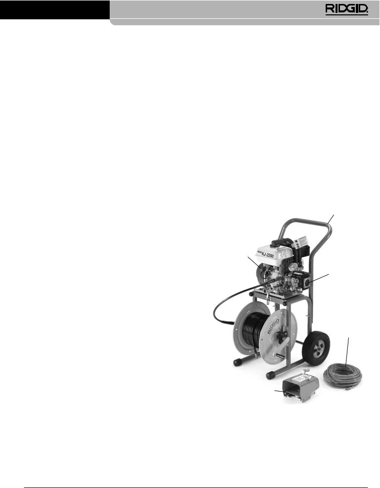
Dégorgeoirs haute-pression KJ-2200 et KJ-3100
• Respectez les consignes dʼhygiène. Lavez vos mains, ainsi que toute autre partie du corps éventuellement exposée au contenu de la conduite dʼévacuation, à lʼeau chaude savonneuse après chaque manipulation ou utilisation du matériel de curage. Ne pas manger ou fumer lors de la manipulation ou utilisation du matériel de curage. Cela limitera les risques de contamination en cas de contact avec des produits toxiques ou infectieux.
• Ne jamais pulvériser de produits toxiques ou inflammables. Cela limitera les risques de brûlure, dʼincendie, dʼexplosion et autres blessures.
• Lʼessence et ses vapeurs sont très inflammables et explosives. Afin de limiter les risques de brûlure, dʼexplosion et de grave blessures, consultez le manuel du moteur thermique concerné pour les précautions applicables à la manipulation et utilisation de lʼessence.
• Les moteurs thermiques rejettent du monoxyde de carbone, un gaz toxique à la fois incolore et inodore. Lʼinhalation du monoxyde de carbone peut provoquer des nausées, des évanouissements et la mort. Ne jamais démarrer ou utiliser un moteur thermique dans un local fermé, même avec les portes ou fenêtres ouvertes. A nʼutiliser quʼà lʼextérieur.
• Les surfaces brûlantes risquent de provoquer des brûlures ou des incendies. Eloignez-vous, ainsi que tous matériaux combustibles, des surfaces brûlantes.
• Avant toute utilisation, familiarisez-vous avec ce mode dʼemploi, ainsi que le mode dʼemploi du moteur thermique et des consignes visant lʼensemble du matériel utilisé. Le non respect de lʼensemble des consignes dʼutilisation et de sécurité ci-devant pourrait entraîner des dégâts matériels et/ou de graves lésions corporelles.
Lorsque cela sera nécessaire, la déclaration de conformité CE (890-011-320.10) sera jointe à ce manuel sous la forme d'un livret distinct.
En cas de questions concernant ce produit RIDGID® :
– Consultez votre distributeur RIDGID.
– Consultez les sites www.RIDGID.com ou www.RIDGID.eu pour localiser le représentant RIDGID le plus proche.
– Consultez les services techniques de RIDGID par mail adressé à rtctechservices@emerson.com, ou, à partir des États-Unis et du Canada, en composant le (800) 519-3456.
Description, caractéristiques techniques et équipements de base
Description
Les dégorgeoirs haute-pression à moteur thermique RIDGID® sont des machines à jet dʼeau portables qui font appel à une combinaison de pression et de flux hydraulique pour curer les conduites dʼévacuation des matières grasses, sédiments et racines quʼelles contiennent. Leur tuyau haute-pression est propulsé le long de la canalisation par un jet propulseur situé à lʼarrière de la buse de curage. Lorsque le tuyau haute-pression est rapatrié, ce jet propulseur sert à laver les parois de la conduite et à évacuer les débris. Lorsquʼil est engagé, le système de pulsation de la machine facilite la négociation des coudes serrés et des siphons. Lʼentraînement de la pompe à piston triplex de ces dégorgeoirs est assuré par un moteur à essence.
Poignées
Contact
Pompe
Tuyau haute-pression
Enrouleur 
Pédale de commande
23

Dégorgeoirs haute-pression KJ-2200 et KJ-3100
Caractéristiques techniques |
|
|
|
|
||
Dégorgeoir |
Puissance |
Pression |
Débit |
Ø conduite |
Poids (sans enrouleur) |
|
moteur (CV) |
(PSI / bar) |
(GPM / liter) |
inch / mm |
lbs / kg |
||
KJ-2200 |
6.5 / 6,5 |
2200 / 150 |
2.4 / 9 |
11/4 - 6 / 32 - 152 |
65 |
/ 30 |
KJ-3100 |
16 |
3000 / 205 |
5.5 / 20 |
2 - 10 / 50 - 250 |
262 |
/ 119 |
Poignées
Porte document
Reel Engine
Pompe
Tuyau Pédale de haute-pression commande
Code date
Le numéro de série de lʼappareil se trouve sur la plaque signalétique rivetée au cadre de la machine. Les 4 derniers chiffres indiquent le mois et lʼannée de sa fabrication. (08 = mois, 10 = année).
Icônes
Mode « pression » Mode « pulsation »
EquipementsLes deux types de dégorgeoirbase haute-pression sont livrés avec les éléments suivants :
• Buses haute-pression adaptées
• Outil de nettoyage de buses
• Pédale de commande FV-1
• Manuel du moteur thermique
Consultez le catalogue RIDGID pour lʼéquipement spécifique de chaque modèle.
Cette machine est prévue pour le curageAVIS IMPORTANTdes conduites dʼévacuation. Utilisée correctement, elle nʼendommagera pas les conduites en bon état de fonctionnement, correctement conçues, construites et entretenues. Face à une conduite dʼévacuation en mauvais état, mal conçue, mal construite ou mal entretenue, e processus de curage risque dʼêtre inefficace et dʼendommager la conduite. Le meilleur moyen dʼapprécier lʼétat dʼune conduite avant son curage est dʼy passer une caméra dʼinspection. Toute utilisation incorrecte de ce dégorgeoir haute-pression pourrait endommager à la fois le dégorgeoir et la conduite. Cette machine risque dʼêtre incapable de dégager certains blocages.
Assemblage de la machine
 AVERTISSEMENT
Respectez le processus d’assemblage suivant afin d’éviter de graves blessures en cours d’utilisation de la machine, et de limiter les risques de l’endommager.
Ces dégorgeoirs sont livrés sans huileAVISdansIMPORTANTle moteur. Faire tourner le moteur sans huile entraînerait sa défaillance. Ajoutez de lʼhuile avant sa première mise en route. Reportez-vous au manuel du moteur pour les consignes spécifiques visant le remplissage et la sélection dʼhuile.
Pompe :
Huile de pompe et de transmission
Retirez le bouchon en tête de la pompe et remplacez-le par le reniflard de puits de jauge. Faire tourner le dégorgeoir haute-pression avec le bouchon en place pourrait endommager les joints de la pompe.
24
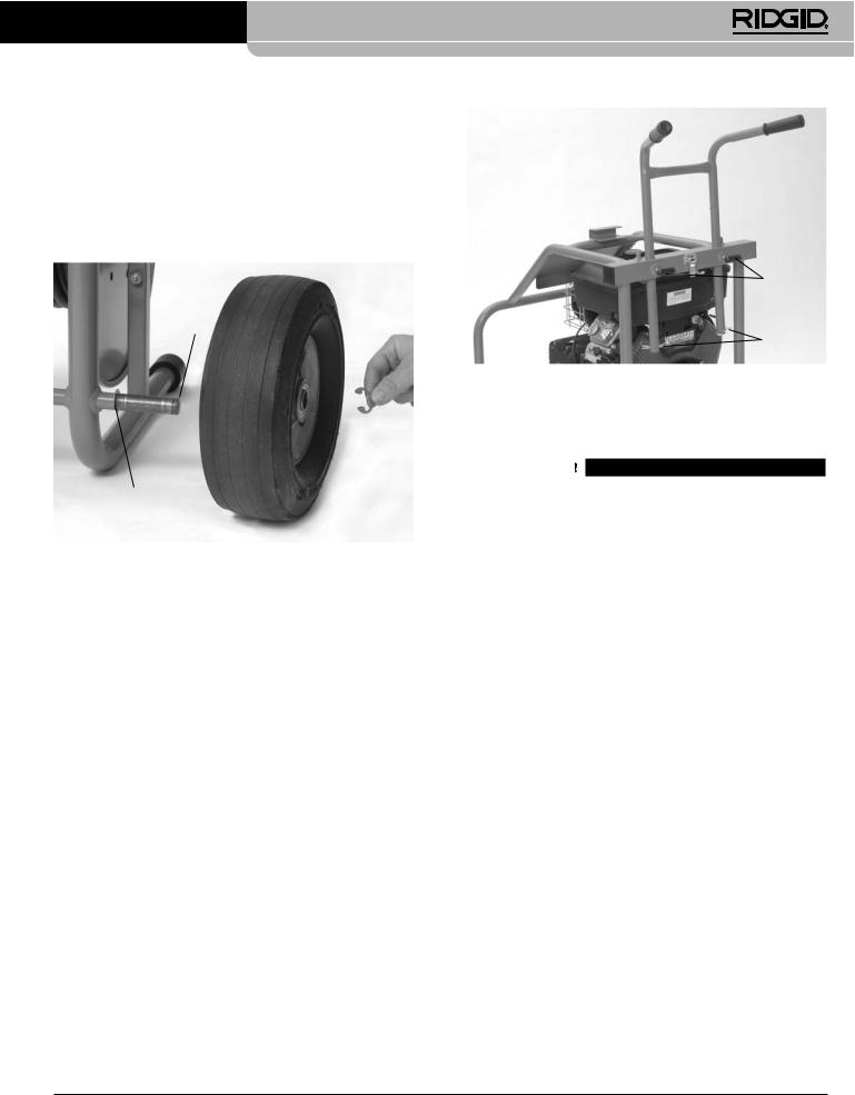
Dégorgeoirs haute-pression KJ-2200 et KJ-3100
Vérifiez le niveau dʼhuile selon les consignes de la section Entretien.
Transmission (KJ-3100 uniquement) : Retirez le bouchon en tête de la transmission et remplacez-le par le reniflard de puits de jauge. Faire tourner le dégorgeoir haute-pression avec le bouchon en place pourrait endommager les joints de la transmission. Vérifiez le niveau dʼhuile selon les consignes de la section Entretien.
Rainure extérieure
Bague de retenue
Chariot de transport pour KJ-2200
1. Engagez une bague de retenue dans la rainure intérieure de chaque extrémité de lʼaxe de roue. (Figure 4.)
2. Enfilez une roue à chaque extrémité de lʼaxe.
3. Engagez un cerclip sur la rainure extérieure de chaque extrémité de lʼaxe afin de retenir les roues.
4. Servez-vous des boulons aveugles et écrous fournis pour attacher la poignée au cadre.
5. Posez lʼensemble moteur/pompe sur le cadre en alignant les orifices de son embase sur les broches du chariot. Servez-vous des loquets du chariot pour arrimer lʼensemble moteur/pompe. Assurez-vous que cet ensemble est solidement arrimé.
KJ-3100 Assemblage de la poignée
1. Introduisez la poignée à travers les deux orifices de la traverse arrière du cadre. (Figure 5.)
2. Introduisez une broche à ressort dans chacun des trous en bout de poignée afin de lʼempêcher dʼêtre retirée.
3. Engagez les molettes filetées dans la traverse arrière du cadre. Réglez la poignée à la hauteur voulue, puis serrez les molettes pour la fixer.
Molettes
filetées
Broches à
ressort
Contrôle préalable
 AVERTISSEMENT
Examinez le égorgeoir avant chaque utilisation afin de pouvoir corriger toute anomalie éventuelle qui pourrait entraîner de graves lésions corporelles et endommager la machine.
Portez systématiquement des lunettes de sécurité, des gants et tout autre équipement de protection individuelle approprié lors de l’inspection du dégorgeoir afin de vous protéger contre les produits
chimiques1. Vérifiez etquebactla cléériesde contactéventuellemdu moteurnt seprésentstrouve en. position OFF.
2. Eliminez toutes traces dʼhuile, de graisse et de crasse du matériel, y compris des poignées et commandes. Cela facilitera son inspection et assurera une meilleure prise en main de la machine.
3. Examinez le dégorgeoir haute-pression et ses accessoires pour :
• Un bon assemblage de lʼensemble de ses composants
• Signes de composants endommagés, usés, manquants, désalignés, grippés ou desserrés
• La présence et la lisibilité des étiquettes de sécurité (Figure 6).
• Toute autre anomalie qui serait susceptible de nuire à la sécurité et au bon fonctionnement du matériel.
En cas dʼanomalie, ne pas utiliser le dégorgeoir avant dʼavoir corrigé le problème.
25

Dégorgeoirs haute-pression KJ-2200 et KJ-3100
Figure 6B – Etiquettes de sécurité du KJ-2200
Figure 6C – Etiquettes de sécurité du KJ-3100
4.Nettoyez le filtre/tamis dʼarrivée dʼeau. Pour ce faire, dévissez le couvercle end fond du filtre. Son encrassement du filtre et lʼaccumulation de débris peuvent restreindre lʼarrivée dʼeau à la pompe et limiter les performances de la machine.
 Filtre
Figure 7 – Filtre/tamis dʼarrivée dʼeau
5.Examinez les orifices de la buse haute-pression pour signes de détérioration ou dʼobstruction. Les obstructions éventuelles peuvent être éliminées à lʼaide de lʼoutil de nettoyage de buse. Faites attention de ne pas élargir les orifices de buse lors de leur nettoyage. Une buse endommagée ou ayant des orifices élargis peut nuire aux performances du dégorgeoir et devrait être remplacée.
6.Examinez les tuyaux haute-pression et leurs raccords pour signes dʼusure ou de détérioration. En cas de plissage, de fissuration de rupture ou dʼusure de sa gaine, remplacez immédiatement le tuyau en question. Un tuyau haute-pression endommagé risque dʼéclater ou de fuir avec suffisamment de force ou pression pour causer de graves blessures. Les tuyaux et raccords de remplacement devraient avoir une résistance nominale au moins égale à la pression du dégorgeoir.
7.Examinez et entretenez le moteur thermique selon les consignes de son manuel.
26
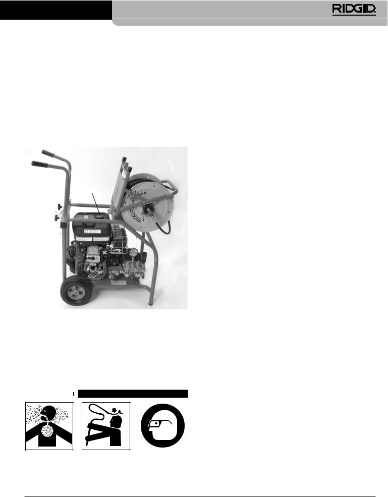
Dégorgeoirs haute-pression KJ-2200 et KJ-3100
8.Vérifiez le niveau de carburant du moteur. Pour accéder au bouchon du réservoir dʼessence du KJ-3100, ouvrez le loquet de lʼenrouleur et poussez lʼenrouleur en avant jusquʼà ce quʼil repose sur le cadre (Figure 8). Au besoin, faites lʼappoint dʼessence sans plomb. Reportez-vous au manuel du moteur pour de plus amples détails. Prenez les précautions dʼusage lors de la manipulation de lʼessence. Faites le plein dans un endroit bien ventilé. Ne remplissez pas le réservoir à raz bord et ne laissez pas lʼessence se déverser. Assurez-vous que le bouchon de remplissage est bien fermé.
Bouchon du réservoir dʼessence
9.Vérifiez le niveau dʼhuile de la pompe et, le cas échéant, de la transmission. Au besoin, faites lʼappoint dʼhuile selon les consignes de la section Entretien.
Préparation de la machine et du chantier
 AVERTISSEMENT
Afin de vous protéger contre la présence éventuelle de produits chimiques et de bactéries, portez systématiquement des lunettes de sécurité, des gants et tout autre équipement de protection approprié lors de la préparation du dégorgeoir haute-pres-
sion. Le port de chaussures antidérapantes à semelles en caoutchouc peut limiter les risques de dérapage sur les sols mouillés.
Les moteurs thermiques rejettent du monoxyde de carbone, un gaz toxique à la fois incolore et inodore. L’inhalation du monoxyde de carbone peut provoquer des nausées, des évanouissements et la mort. Ne jamais démarrer ou utiliser un moteur thermique dans un local fermé, même avec les portes ou fenêtres ouvertes. A n’utiliser qu’à l’extérieur.
Respectez les procédures suivantes visant la préparation du dégorgeoir haute-pression et du chantier afin de limiter les risques de pénétration cutanée, de brûlure chimique, d’infection, d’inhalation de monoxyde de carbone et autres lésions, et afin d’éviter
d’endommager le dégorgeoirvousl i-même.
1. Examinez le chantier pour assurer :
• Dʼun éclairage suffisant.
• De lʼabsence de liquides, vapeurs ou poussières combustibles qui risqueraient de sʼenflammer. Le cas échéant, identifiez et éliminez toutes sources de combustible avant dʼintervenir sur le chantier. Les dégorgeoirs haute-pression ne sont pas blindés et peuvent produire des étincelles.
• De la présence dʼun endroit dégagé, propre et sec pour lʼinstallation de la machine et de son utilisateur. Au besoin, asséchez la plate-forme de travail ou rapportez-y un plancher en bois ou autre matériau.
• Dʼun emplacement à lʼextérieur et bien ventilé pour le dégorgeoir haute-pression. Dans la mesure où le dégorgeoir peut être installé à distance, ne jamais lʼinstaller à lʼintérieur dʼun local, même avec les portes et le fenêtres ouvertes.
• Dʼune alimentation dʼeau adéquate.
• Dʼun passage dégagé permettant de transporter le dégorgeoir haute-pression jusquʼau chantier.
2. Examinez la conduite dʼévacuation ciblée. Si possible, établissez ses points dʼaccès possibles, sa ou ses section(s), sa ou ses longueur(s), la distance à parcourir avant dʼarriver à la fosse ou à lʼégout, la composition du blocage, la présence de produits chimiques, etc. En présence de produits chimiques, il sera nécessaire de contacter le fabricant des produits en question afin de déterminer les mesures de sécurité applicables.
Au besoin, déposez tout élément sanitaire (cuvette de W.C., etc.) pour pouvoir accéder directement à la conduite dʼévacuation. Ne jamais enfiler le tuyau haute-pression du dégorgeoir via un élément sanitaire siphonné, car cela risquerait dʼendommager à la fois le tuyau et lʼélément sanitaire.
3. Choisissez le matériel de curage le mieux adapté à votre application en vous reportant à la section Caractéristiques techniques. Dʼautres types de dégor-
27
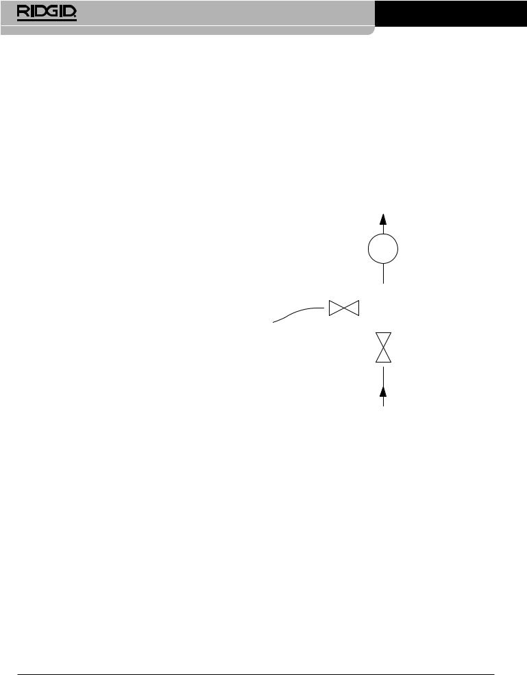
Dégorgeoirs haute-pression KJ-2200 et KJ-3100
geoirs mécaniques et de dégorgeoirs haute-pression sont disponibles dans le catalogue RIDGID et sur les sites www.RIDGID.com ou www.RIDGID.eu.
4. Assurez-vous de lʼinspection préalable appropriée de lʼensemble du matériel.
5. Examinez les lieux afin de déterminer sʼil sera nécessaire dʼériger des barrières de sécurité afin dʼéloigner le public. La présence dʼautres individus à proximité risquerait de distraire lʼutilisateur. Lors des travaux sur la voie publique, prévoyez des cônes ou des barricades pour signaler votre présence aux automobilistes.
6. Au besoin, prévoyez des bâches ou autres moyens de protéger les lieux contre les éclaboussures éventuelles, car le processus de curage est souvent salissant.
7. Amenez le dégorgeoir haute-pression jusquʼà lʼemplacement extérieur prévu via le chemin dégagé prévu. Sʼil est nécessaire de soulever la machine, utilisez les méthodes de manutention appropriées. Faites particulièrement attention en montant et en descendant les escaliers, notamment en ce qui concerne les risques de dérapage. Le port de chaussures antidérapantes aidera à éviter les chutes.
Assurezlimentation-vous que led’eauréseau dʼalimentation utilisé dispose dʼun débit suffisant pour le dégorgeoir haute-pression. Amenez un tuyau dʼarrosage depuis le point dʼeau jusquʼau dégorgeoir. Utilisez la section de tuyau la plus grosse possible sur la plus courte distance possible. Ce tuyau devrait avoir un diamètre intérieur minimum de 3/4 / 19 mm. Prévoyez également un dispositif à clapet anti-"retour approprié afin de respecter la législation en vigueur. Ouvrez le robinet dʼeau et mesurer le temps nécessaire au remplissage dʼun sceau propre de cinq gallons / 18,9 l de capacité. Consultez le tableau suivant pour la durée de remplissage maximale applicable à chaque modèle de dégorgeoir.
Dégorgeoir |
Débit nominal |
Durée maxi de remplissage |
haute-pression |
(GPM / l) |
d’un sceau de 5 gallons / 18,9 l |
|
|
|
KJ-2200 |
2.4 / 9 |
125 secondes |
KJ-3100 |
5.5 / 20 |
55 secondes |
|
||
Un débit dʼeau insuffisant empêchera le dégorgeoir haute- |
||
pression dʼatteindre sa pression nominale et pourrait en- |
||
dommager sa pompe. Examinez lʼeau dans le sceau. La |
||
présence éventuelle de sédiments ou débris pourrait user |
||
la pompe prématurément, obstruer les filtres et les buses |
||
haute-pression, et nuire aux performances du dégorgeoir. |
||
Ne pas utiliser dʼeau en provenance dʼétangs, de lacs ou |
||
autres sources potentiellement contaminées. |
||
Parmi les solutions possibles en cas de débit insuffisant se trouvent le montage dʼun raccord multiple permettant lʼutilisation de plusieurs tuyaux dʼamenée ou lʼemploi dʼune citerne dʼeau.
Lors de lʼutilisation dʼune citerne à eau, effectuez son raccordement selon le schéma ci-dessous (Figure 9) : Le tuyau de relevage allant de la branche perpendiculaire du Té à la citerne peut être soit plongé directement dans la citerne ou branché sur son robinet de sortie, mais il ne doit jamais se trouver à plus de 5 / 12,7 cm au-dessus du fil dʼeau dʼarrivée du dégorgeoir "par risque de désamorçage de la pompe.
Arrivée dʼeau du dégorgeoir Filtre
|
|
|
|
Té |
|
|
|
|
|
|
|
|
||
Tuyau de |
|
|
|
|
|
|
|
||
citerne |
|
Robinet à boule |
||
|
|
|
|
|
|
|
|
|
Alimentation dʼeau |
Figure 9 – Raccordement dʼune citerne à eau
Remplissez le réservoir avant de démarrer le dégorgeoir. Lors du démarrage, coupez lʼarrivée dʼeau. Dès que le dégorgeoir démarre, ouvrez le robinet dʼarrivée. Contrôlez le niveau dʼeau du réservoir et, au besoin, interrompez le curage assez longtemps pour lui permettre de se remplir à nouveau. Ne laissez pas le niveau dʼeau descendre plus bas que lʼembout du tuyau.
Lʼutilisation dʼeau chaude peut améliorer le nettoyage. Ne pas utiliser dʼeau dʼune température de plus de 140ºF / 60°C, car cela pourrait entraîner lʼouverture du clapet de surchauffe de la pompe. Si vous utilisez de lʼeau chaude, prévoyez les équipement de protection individuelle appropriés afin de limiter les risques de brûlure.
Par temps froid, il faut prendre les précautions nécessaires pour éviter que lʼeau gèle dans la pompe, car cela pourrait endommager la pompe.
Assurez-vous que le robinet dʼarrivée du dégorgeoir est fermé avant dʼy raccorder le tuyau dʼalimentation.
28
 Loading...