


1210 Oil-less Threading
Machine
1″ Capacity
OPERATOR’S
MANUAL
•Français – Page 17
•Para ver el castellano vea la página 35
 WARNING!
Read this Operator’s Manual carefully before using this tool. Failure to understand and follow the contents of this manual may result in electrical shock, fire and/or serious personal injury.

1210 Oil-less Threading Machine |
|
Table of Contents |
|
Recording Form for Machine Model and Serial Number............................................................................................ |
1 |
General Safety Information |
|
Work Area Safety ........................................................................................................................................................ |
2 |
Electrical Safety........................................................................................................................................................... |
2 |
Personal Safety ........................................................................................................................................................... |
2 |
Tool Use and Care ...................................................................................................................................................... |
3 |
Service ........................................................................................................................................................................ |
3 |
Specific Safety Information |
|
Foot Switch Safety ...................................................................................................................................................... |
3 |
Machine Safety............................................................................................................................................................ |
3 |
Description, Specifications and Standard Equipment |
|
Description .................................................................................................................................................................. |
4 |
Specifications .............................................................................................................................................................. |
4 |
Standard Equipment.................................................................................................................................................... |
4 |
Machine Assembly |
|
Mounting On The No. 120 Stand................................................................................................................................. |
5 |
Machine Inspection ....................................................................................................................................................... |
5 |
Machine and Work Area Set-Up |
|
Priming The Coolant System....................................................................................................................................... |
7 |
Operating Instructions |
|
Installing Pipe In Threading Machine .......................................................................................................................... |
8 |
Cutting Pipe with No. 354 Cutter ................................................................................................................................. |
8 |
Reaming Pipe with No. 334 Reamer ........................................................................................................................... |
9 |
Threading Pipe with No. 610 Die Head ....................................................................................................................... |
9 |
Threading Pipe with No. 610A Self-Opening Die Head............................................................................................. |
10 |
Removing Pipe From Machine .................................................................................................................................. |
10 |
Transporting Machine................................................................................................................................................ |
10 |
Installing Dies and Adjusting For Size In No. 610 Quick-Opening Die Head ............................................................ |
11 |
Installing Dies and Adjusting For Size In No. 610A Auto-Opening Die Head............................................................ |
11 |
Checking Thread Length ........................................................................................................................................... |
12 |
Accessories ................................................................................................................................................................. |
12 |
Maintenance Instructions |
|
Jaw Insert Replacement............................................................................................................................................ |
13 |
Replacing Carbon Brushes ....................................................................................................................................... |
13 |
Machine Storage .......................................................................................................................................................... |
13 |
Service and Repair ...................................................................................................................................................... |
14 |
Wiring Diagram ............................................................................................................................................................ |
15 |
Lifetime Warranty.......................................................................................................................................... |
Back Cover |
ii |
Ridge Tool Company |

1210
Oil-less Threading Machine
1210 Oil-less Threading Machine
Record Serial Number below and retain product serial number which is located on nameplate.
Serial
No.

1210 Oil-less Threading Machine
General Safety Information
WARNING! Read and understand all instructions. Failure to follow all instructions listed below may result in electric shock, fire, and/or serious personal injury.
SAVE THESE INSTRUCTIONS!
Work Area Safety
•Keep your work area clean and well lit. Cluttered benches and dark areas invite accidents.
•Do not operate tools in explosive atmospheres, such as in the presence of flammable liquids, gases, or dust. Tools create sparks which may ignite the dust or fumes.
•Keep by-standers, children, and visitors away while operating a tool. Distractions can cause you to lose control.
•Keep floors dry and free of slippery materials such as oil. Slippery floors invite accidents.
Electrical Safety
•Grounded tools must be plugged into an outlet, properly installed and grounded in accordance with all codes and ordinances. Never remove the grounding prong or modify the plug in any way. Do not use any adapter plugs. Check with a qualified electrician if you are in doubt as to whether the outlet is properly grounded. If the tool should electrically malfunction or break down, grounding provides a low resistance path to carry electricity away from the user.
Cover of  grounded
  outlet box
Grounding Prong |
Grounding Prong |
•Avoid body contact with grounded surfaces. There is an increased risk of electrical shock if your body is grounded.
•Don’t expose electrical tools to rain or wet conditions. Water entering a tool will increase the risk of electrical shock.
•Do not abuse cord. Never use the cord to pull the plug from an outlet. Keep cord away from heat, oil, sharp edges or moving parts. Replace damaged
cords immediately. Damaged cords increase the risk of electrical shock.
•When operating a tool outside, use an outdoor extension cord marked “W-A” or “W”. These cords are rated for outdoor use and reduce the risk of electrical shock.
•Use only three-wire extension cords which have three-prong grounding plugs and three-pole receptacles which accept the tool’s plug. Use of other extension cords will not ground the tool and increase the risk of electrical shock.
•Use proper extension cords. (See chart.) Insufficient conductor size will cause excessive voltage drop, and loss of power.
Minimum Wire Gauge for Extension Cord
Nameplate |
|
Total Length (in feet) |
|||
Amps |
|
||||
|
|
|
|
||
|
|
|
|
|
|
|
|
0 – 25 |
|
26 – 50 |
51 – 100 |
0 |
– 6 |
18 AWG |
|
16 AWG |
16 AWG |
|
|
|
|
|
|
6 |
– 10 |
18 AWG |
|
16 AWG |
14 AWG |
10 |
– 12 |
16 AWG |
|
16 AWG |
14 AWG |
12 |
– 16 |
14 AWG |
|
12 AWG |
NOT RECOMMENDED |
|
|
|
|
|
|
•Keep all electric connections dry and off the ground. Do not touch plugs or tool with wet hands.
Reduces the risk of electrical shock.
Personal Safety
•Stay alert, watch what you are doing and use common sense when operating a power tool. Do not use tool while tired or under the influence of drugs, alcohol, or medications. A moment of inattention while operating power tools may result in serious personal injury.
•Dress properly. Do not wear loose clothing or jewelry. Contain long hair. Keep your hair, clothing, and gloves away from moving parts. Loose clothes, jewelry, or long hair can be caught in moving parts.
•Avoid accidental starting. Be sure switch is OFF before plugging in. Plugging in tools that have the switch ON invites accidents.
•Remove adjusting keys before turning the tool ON. A wrench or a key that is left attached to a rotating part of the tool may result in personal injury.
•Do not over-reach. Keep proper footing and balance at all times. Proper footing and balance enables better control of the tool in unexpected situations.
•Use safety equipment. Always wear eye protection. Dust mask, non-skid safety shoes, hard hat, or
2 |
Ridge Tool Company |

1210 Oil-less Threading Machine
hearing protection must be used for appropriate conditions.
Tool Use and Care
•Do not use if switch does not turn it ON or OFF.
Any tool that cannot be controlled with the switch is dangerous and must be repaired.
•Disconnect the plug from the power source before making any adjustments, changing accessories or storing the tool. Such preventive safety measures reduce the risk of starting the tool accidentally.
•Store idle tools out of the reach of children and other untrained persons. Tools are dangerous in the hands of untrained users.
•Check for misalignment or binding of moving parts, breakage of parts and any other condition that may affect the tool’s operation. If damaged, have the tool serviced before using. Many accidents are caused by poorly maintained tools.
•Use only accessories that are recommended for your tool. Accessories that may be suitable for one tool may become hazardous when used on another tool.
•Keep handles dry and clean; free from oil and grease. Allows for better control of the tool.
Service
•Tool service must be performed only by qualified repair personnel. Service or maintenance performed by unqualified repair personnel could result in injury.
•When servicing a tool, use only identical replacement parts. Follow instructions in the Maintenance Section of this manual. Use of unauthorized parts or failure to follow maintenance instructions may create a risk of electrical shock or injury.
Specific Safety Information
 WARNING
Read this operator’s manual carefully before using the 1210 Threading Machine. Failure to understand and follow the contents of this manual may result in electrical shock, fire and/or serious personal injury.
Call the Ridge Tool Company, Technical Service Department at (800) 519-3456 if you have any questions.
 WARNING Foot Switch Safety
Using a power drive or threading machine without a foot switch increases the risk of serious injury. A foot switch provides better control by letting you shut off the motor by removing your foot. If clothing should become caught in the machine, it will continue to wind up, pulling you into the machine. Because the machine has high torque, the clothing itself can bind around your arm or other body parts with enough force to crush or break bones.
Machine Safety
•Threading Machine is made to thread and cut pipe. Follow instructions on proper use of this machine. Do not use for other purposes such as turning winches. Other uses or modifying this threading machine for other applications may increase the risk of serious injury.
•Support long heavy pipe with pipe supports. This practice will prevent tipping.
•Do not wear gloves or loose clothing when operating machine. Keep sleeves and jackets buttoned. Do not reach across the machine or pipe. Clothing can be caught by the pipe or machine resulting in entanglement and serious injury.
•Operate machine from side with REV/OFF/FOR switch. Eliminates need to reach over the machine.
•Do not use this machine if the foot switch is broken or missing. Foot switch is a safety device to prevent serious injury.
•Keep hands away from rotating pipe and fittings. Stop the machine before wiping pipe threads or screwing on fittings. Allow the machine to come to a complete stop before touching the pipe or machine chucks. This practice will prevent entanglement and serious injury.
•Do not use this machine to make or break fittings.
This practice is not an intended use of the machine and can result in serious injury.
•Tighten chuck handwheel and engage rear centering devise on the pipe before turning on the machine. Prevents oscillation of the pipe.
•Keep covers in place. Do not operate the machine with covers removed. Exposure to moving parts may result in entanglement and serious injury.
•Allow threads to cool before handling. Threads will be hot to the touch immediately after threading.
•Use in ventilated area. Prevents accumulation of coolant vapors.
Ridge Tool Company |
3 |

1210 Oil-less Threading Machine
Description, Specifications and
Standard Equipment
Description
The RIDGID Model 1210 Oil-Less Threading Machine is an electric motor-driven machine that centers and chucks pipe and rotates it while cutting, reaming and threading operations are performed. Threading dies are mounted in a quick-opening die head. An integral coolant system is provided to reduce the temperature of the workpiece and lubricate it during the threading operation.
Specifications
Threading Capacity |
.......Pipe 1/2″ through 1″ |
Cut-Off Capacity............ |
Pipe 1/2″ through 1″ |
Operating Speed ........... |
25 RPM (No Load) |
Motor: |
|
Type ............................ |
Universal |
Volts ............................ |
115V Single Phase AC |
|
50-60 HZ |
Amps ........................... |
6.4 |
Controls ......................... |
ON/OFF Toggle Switch and |
|
ON/OFF Foot Switch |
Chuck ............................ |
Hammer-Style with |
|
Replaceable Inserts; Cam |
|
Action Rear Chuck |
Coolant System ............. |
16 Oz. Integral Coolant |
|
Reservoir with Gerotor Pump |
Weight ........................... |
59 lbs. |
Standard Equipment
(Figure 1)
•Model 610 Quick-Opening Die Head, 1/2″ – 1″ NPT
•1/2″ – 3/4″ Oil-less Gold NPT Dies
•1″ Oil-less Gold NPT Dies
•Model 334 Blade-Type Reamer
•Model 354 Roll-Type, Self-Centering Cutter
•1 Quart RIDGID Thread Cutting Coolant
|
Cutter |
|
Die Head |
|
Chuck |
Rear Centering |
Handwheel |
Device |
|
|
Reamer |
Carrying |
|
Handle |
Carrying |
|
Handle |
|
Carriage |
ON/OFF |
Handwheel |
|
|
Switch |
Foot |
|
|
|
Switch |
|
Coolant Level |
|
Sight Glass |
Reservoir
Vent Cap
Foot Switch Clip
Figure 1 – 1210 Threading Machine
Machine Assembly
 WARNING
To prevent serious injury, proper assembly of the Threading Machine is required. The following procedures should be followed:
The 1210 Threading Machine can be used on a bench or mounted to the Model 120 Stand. The No. 120 Stand is a three-legged folding stand (Figure 2). Guide/pin assemblies are mounted on top of each leg to hold the 1210 Threading Machine in place.
4 |
Ridge Tool Company |

1210 Oil-less Threading Machine
Mounting On The No. 120 Stand
1.To set-up the Model 120 Stand, pivot the two (2) outside legs about the center section of the stand until the plunger pins lock into place. (Figure 2)
2.The stationary center leg holds a larger guide. This center leg and guide must be positioned at the REAR of the machine.
3.To mount the Model 1210 Threading Machine on the No. 120 Stand, grasp the Model 1210 machine by both the front and rear carrying handles.
4.Position the Model 1210 so the REAR of the machine is above the guide of the stationary center leg of the stand. The front corners of the machine should be above the two (2) smaller guides.
5.Lower the machine onto the mounting pins of the stand. The guides will help to properly position the machine. Insert retaining pin through hole in front guide of stand to capture machine. (Figure 3)
 WARNING Before letting go of the Model 1210, be sure the stand mounting pins are properly engaged into the threading machine. Retaining pin must be properly inserted before using the machine.
Figure 2 – Model 120 Stand in OPEN Position.
Figure 3 – 1210 Machine Mounted on Model 120 Stand
Machine Inspection
 WARNING
To prevent serious injury, inspect your Threading Machine. The following inspection procedures should be performed on a daily basis:
1.Make sure Threading Machine is unplugged and the switch is set to the OFF position (Figure 1).
2.Clean the speed chuck jaws with a wire brush.
3.Inspect the jaw inserts for excessive wear. Refer to the Maintenance Instructions if they need to be replaced.
4.Make sure the foot switch is present and attached to the Threading Machine (Figure 1).
 WARNING Do not operate the Threading Machine without a foot switch.
5.Inspect the power cord and plug for damage. If the plug has been modified, is missing the grounding pin or if the cord is damaged, do not use the Threading Machine until the cord has been replaced.
6.Inspect the Threading Machine for any broken, miss-
Ridge Tool Company |
5 |
1210 Oil-less Threading Machine
ing, misaligned or binding parts as well as any other conditions which may affect the safe and normal operation of the machine. If any of these conditions are present, do not use the Threading Machine until any problem has been repaired.
7.Use tools and accessories that are specifically designed for your Threading Machine and meet the needs of your application. The correct tools and accessories allow you to do the job successfully and safely. Accessories suitable for use with other equipment may be hazardous when used with this Threading Machine.
8.Clean any oil, grease or dirt from all handles and controls. This reduces the risk of injury due to a tool or control slipping from your grip.
9.Inspect the cutting edges of your tools and dies. If necessary, have them replaced prior to using the Threading Machine.
NOTE! Use sharp dies at all times. Dull dies require more power from the motor and produce poor quality threads.
10.Clean metal shavings and other debris from the chip tray.
Machine and Work Area Set-Up
 WARNING
2.Clean up the work area prior to setting up any equipment.
3.If the workpiece extends more than four (4) feet beyond the Threading Machine, use one or more pipe stands to prevent tipping and the oscillation of the pipe.
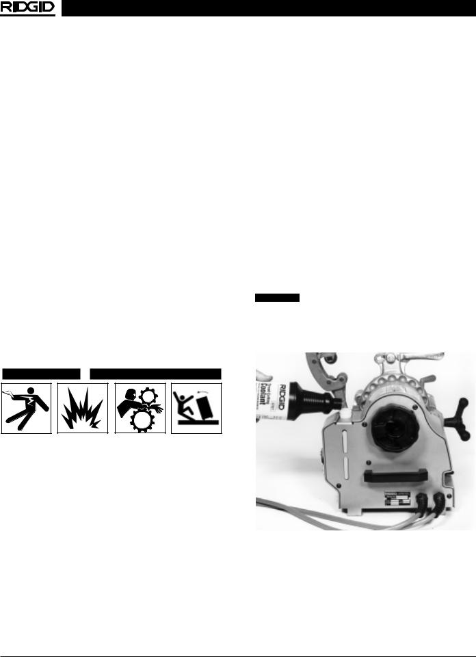
4.Check level of RIDGID Threading Cutting Coolant and fill as necessary.
NOTE! RIDGID Thread Cutting Coolant is engineered specifically for use with the 1210 Threading Machine. It is designed to quickly cool the pipe and leave a clean, dry thread ready for immediate installation.
•Observe coolant level in the reservoir by viewing the sight glass at the rear of the Model 1210 (Figure 4).
•Unscrew the reservoir cap and pour the coolant into the reservoir (Figure 4).
NOTE! Reservoir will hold approximately 16 oz. of fluid.
• Replace the reservoir cap.
CAUTION Use of fluids other than RIDGID Thread Cutting Coolant will void the RIDGID 1210 warranty and may cause damage to the threading machine and threading dies. RIDGID Thread Cutting Coolant should NOT be used in or with any other RIDGID threading equipment.
To prevent serious injury, proper set-up of the machine and work area is required. The following procedures should be followed to set-up the machine:
1.Locate a work area that has the following:
•Adequate lighting
•No flammable liquids, vapors or dust that may ignite.
•Grounded electrical outlet
•Clear path to the electrical outlet that does not contain any sources of heat or oil, sharp edges or moving parts that may damage electrical cord.
•Dry place for machine and operator. Do not use the machine while standing in water.
•Level ground
•Adequate ventilation to prevent accumulation of coolant vapors
Sight 
Glass 
Figure 4 – Filling Coolant Reservoir
6 |
Ridge Tool Company |
1210 Oil-less Threading Machine
Sight 
Glass 
Figure 5 – Full Coolant Reservoir
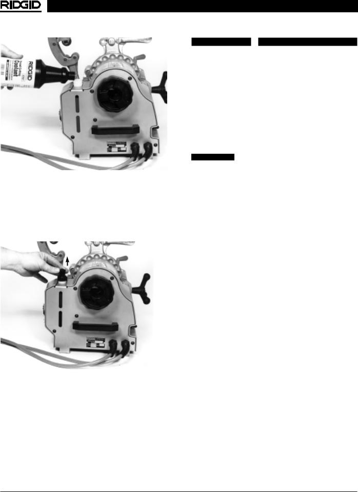
5.Pull the vent at the top of the reservoir cap to the OPEN position (Figure 6).
NOTE! The vent must be in the OPEN position during operation of the machine. If the vent is left closed, coolant flow will be hindered.
6. Make sure ON switch is in the OFF position.
Figure 6 – Reservoir Vent Open
7.Position the foot switch so that the operator can safely control the machine, tools and workpiece.
•Stand facing the directional switch.
•Have convenient access to the directional switch, tools and chucks without reaching across the machine.
8.Plug the Threading Machine into the electrical outlet making sure to position the power cord along the clear path selected earlier. If the power cord does not reach the outlet, use an extension cord in good condition.
 WARNING
To avoid electrical shock and electrical fires, never use an extension cord that is damaged or does not meet the following requirements:
•The cord has a three-prong plug similar to shown in Electrical Safety section.
•The cord is rated as “W” or “W-A” if being used outdoors.
•The cord has sufficient wire thickness (14 AWG). If the wire thickness is too small, the cord may overheat, melting the cord’s insulation or causing nearby objects to ignite.
 WARNING To reduce risk of electrical shock, keep all electrical connections dry and off the ground. Do not
touch plug with wet hands.
9.Check the Threading Machine to insure it is operating properly.
•Flip the switch to ON. Press and release the foot switch. Check that the Threading Machine rotates in a counterclockwise direction as you are facing the front chuck. Have the Threading Machine serviced if it rotates in the wrong direction or if the foot switch does not control its stopping or starting.
•Depress and hold the foot switch. Inspect the moving parts for misalignment, binding, odd noises or any other unusual conditions that may affect the safe and normal operation of the machine. If such conditions are present, have the Threading Machine serviced.
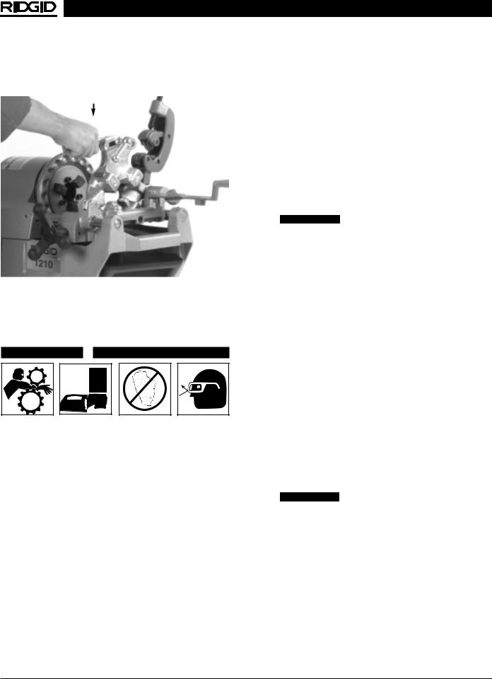
•Check the coolant system by placing the die head in the DOWN position. Press down on the die head (Figure 7). With the foot switch depressed, the coolant should flow from the die head as continuous stream of drops (approximately one (1) drop per second).
•Release the foot switch and flip the switch to OFF.
NOTE! If 1210 has not been used for some time or the die head has been removed from the machine, coolant system must be primed.
Priming The Coolant System
1.Check that the reservoir vent cap is in the OPEN position (Figure 6).
2.Swing the die head in the DOWN position and turn the switch to the ON position.
3.Depress and hold down on the foot switch.
4.Press DOWN on the die head (Figure 7). The die head will actuate a poppet valve that is in the carriage.
Ridge Tool Company |
7 |
1210 Oil-less Threading Machine
5.When the coolant drops are visible from the die head, release the die head. Coolant system is now primed.
6.Release the foot switch and remove your foot.
Figure 7 – Priming Coolant System
Operating Instructions
 WARNING
Do not wear gloves or loose clothing when operating Threading Machine. Keep sleeves and jackets buttoned. Do not reach across the machine or pipe.
Do not use this Threading Machine if the foot switch is broken or missing. Always wear eye protection to protect eyes from dirt and other foreign objects.
Keep hands away from rotating pipe and fittings. Stop the machine before wiping pipe threads or screwing on fittings. Allow the machine to come to a complete stop before touching the pipe or machine chucks.
Do not use this machine to make or break fittings. This practice is not an intended use of this Threading Machine.
Use in ventilated area to prevent accumulation of coolant vapors.
Installing Pipe In Threading Machine
1.Check to insure the cutter, reamer and die head are swung to the rear of the carriage.
2.Mark the pipe at the desired length if it is being cut to length.
3.Insert the pipe into the Threading Machine so that the end to be worked or the cutting mark is located about 4 inches to the front of the speed chuck jaws.
4.Insert workpieces less than 2 feet long from the front of the machine. Insert longer pipes through either end so that the longer section extends out beyond the rear of the Threading Machine.
 WARNING To avoid equipment tip-overs, position the pipe supports under the workpiece.
5.Tighten the rear centering device around the pipe by using a counterclockwise rotation of the handwheel when viewed from rear of the Threading Machine. This prevents movement of the pipe that can result in poor thread quality.
6.Secure the pipe by using repeated and forceful counterclockwise spins of the speed chuck handwheel when viewed from the front of the Threading Machine. This action “hammers” the jaws tightly around the pipe.
Cutting Pipe with No. 354 Cutter
1.Check to insure the reamer and die head are in the UP position (Figure 8).
2.Move pipe cutter down onto pipe and move carriage with lever to line up cutter wheel with mark on pipe
(Figure 8).
3.Tighten cutter feedscrew handle while keeping the cutter wheel aligned with the mark.
4.Assume the correct operating posture.
 WARNING This will allow you to maintain proper balance and to safely keep control of the machine and tools.
•Be sure you can quickly remove your foot from the foot switch.
•Stand facing the ON/OFF switch.
•Be sure you have convenient access to tools and chucks.
•Do not reach across the machine or workpiece.
5.Flip the switch to ON (Forward).
6.Grasp the pipe cutter’s feed handle with both hands
(Figure 8).
8 |
Ridge Tool Company |
1210 Oil-less Threading Machine
Figure 8 – Cutting Pipe with No. 354 Cutter
7.Depress and hold down the foot switch with the left foot.
8.Tighten the feedscrew handle slowly and continuously until the pipe is cut. Do not force the cutter into the workpiece.
9.Release the foot switch and remove your foot.
10.Swing pipe cutter back to the UP position.
Reaming Pipe with No. 334 Reamer
1.With cutter and die head in their UP position, swing reamer into its operating position (Figure 9).
2.Check the ON/OFF switch to insure it is in the ON position. Depress and hold the foot switch down.
3.Feed the carriage handwheel towards the pipe
(Figure 9).
4.With slight handwheel pressure, feed reamer into pipe to achieve desired ream.
5.Release foot switch and return the reamer to its UP position.
Threading Pipe with No. 610 Die Head
NOTE! The 610 or 610A Die Head is designed for use ONLY with the 1210 Threading Machine. These die heads are NOT compatible with any other RIDGID threading equipment. No other RIDGID die heads will fit on the Model 1210 Threading Machine.
1.Check to insure the cutter and reamer are to the rear of the carriage (Figure 10).
2.Lower die head into threading position.
3.Check that the proper size dies are in the die head. Distinct die sets are required for 1/2″ – 3/4″ and 1″ pipe diameters.
4.Set die head to proper size and rotate throwout lever to CLOSED position.
NOTE! Refer to the section on the 610 Die Head for instructions on changing dies and adjusting for proper size.
5.With the control switch in the ON position, step on foot switch and feed the carriage handwheel towards the pipe. Slight pressure on the handwheel will start dies.
NOTE! Coolant flow will begin automatically during threading. COOLANT FLOW WILL BE CONTINUOUS STREAM OF DROPS! In addition to producing better quality threads, coolant will cool the workpiece through evaporation.
6.When thread is complete, rotate throwout lever to OPEN position, retracting dies.
7.Remove foot from foot switch.
8.Check the thread length and depth (Figure 18).
NOTE! Slight die head depth adjustment may be necessary due to variations in the pipe fittings.
Throwout Lever (in CLOSED position)
Figure 10 – Threading Pipe with No. 610 Die Head
Figure 9 – Reaming Pipe with No. 334 Reamer
Ridge Tool Company |
9 |

1210 Oil-less Threading Machine
Threading Pipe with No. 610A
Self-Opening Die Head
NOTE! The No. 610A is available only as a BSPT Die Head.
1.Check to insure the cutter and reamer are to the rear of the carriage.
2.Lower die head into threading position.
3.Check that the proper size dies are in the die head. Distinct die sets are required for 1/2″ – 3/4″ and 1″ pipe diameters.
4.Set die head to proper size and push cocking lever forward until the trigger cocks (Figure 11).
NOTE! Refer to the section on the 610A Die Head for instructions on changing dies and adjusting for proper size.
5.With the control switch in the ON position, step on foot switch and feed the carriage handwheel towards the pipe. Slight pressure on the handwheel will start dies.
NOTE! Coolant flow will begin automatically during threading. COOLANT FLOW WILL BE A CONTINUOUS STREAM OF DROPS.
6.When thread is complete, die head trigger will contact end of pipe and automatically retract the dies.
7.Release foot switch and remove your foot.
8.Check the thread length and depth (Figure 18).
NOTE! Slight die head depth adjustment may be necessary due to variations in the pipe fittings.
Toggle Knob
Trigger
Cocking Lever
Figure 11 – 610A Die Head In Cocked Position. Note Position of Trigger and Cocking Lever.
Removing Pipe From The Machine
1.Use repeated and forceful clockwise spins of the speed chuck handwheel at the front of the machine to release the workpiece from the speed chuck jaws.
2.If necessary, loosen the rear centering device using a clockwise rotation of the handwheel at the rear of the machine.
3.Slide the workpiece out of the Threading Machine, keeping a firm grip on the workpiece as it clears the machine.
 WARNING To avoid injury from falling parts or equipment tip-overs when handling long workpieces, make sure that the end farthest from the machine is supported prior to removal.
Transporting Machine
1.Make sure machine is unplugged from the power source.
2.Clean chips and other debris from the chip tray.
3.Push the vent at the top of the reservoir cap to the CLOSED position. Check that the reservoir cap is screwed on tightly.
4.Place the cutter, reamer and die head in the DOWN position. (Figure 12)
5.Disengage the Model 1210 from the Model 120 Stand by removing retaining pin. Grasp both front and rear carrying handles of the 1210 and lift the machine straight up and off the mounting pins.
6.Slide foot switch onto the foot switch clip (Figure 13).
7.Fold the Model 120 Stand by releasing the plunger pin on each pivoting leg. Pivot each leg back toward the stationary center leg (Figure 12).
Figure 12 – 1210 and 120 Stand Ready For Transport
10 |
Ridge Tool Company |
1210 Oil-less Threading Machine
Figure 13 – Foot Switch In Carrying Position
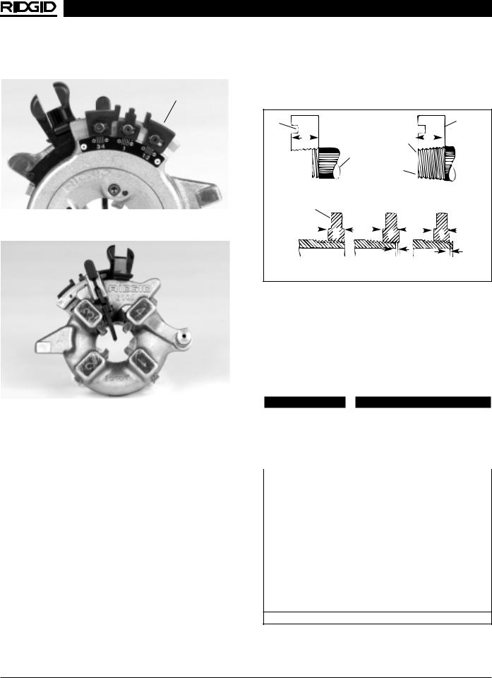
Installing Dies and Adjusting For Size In No. 610 Quick-Opening Die Head
NOTE! The universal die head (Figure 14) for right hand threads requires two sets of dies to thread pipe ranging from 1/2″ through 1″ . One set of dies is required for each of the following pipe size ranges: (1/2″ - 3/4″ ) and (1″ ).
1.With machine unplugged, remove die head.
2.Lay die head on bench with numbers up.
3.Flip throwout lever to OPEN position.
4.Loosen clamp lever approximately three full turns.
5.Lift tongue of clamp lever washer up out of slot under size bar. Slide throwout lever all the way to the end of slot in the OVER direction on size bar (CHANGE DIES arrow on rear of cam plate).
6.Remove worn dies from die head.
7.Insert new dies to indicator line. Die numbers 1 through 4 on the dies must agree with those on the die head.
8.Slide throwout lever back so that tongue of clamp lever washer will drop in slot under size bar.
9.Adjust die head size bar until index line on link is aligned with proper size mark on size bar.
10.Tighten clamp lever.
NOTE! If oversize or undersize threads are required, set the index line in direction of OVER or UNDER size mark on size bar.
Washer
Index Line
|
Head |
Link |
|
Throwout |
Clamp Lever |
Lever |
|
|
Size Bar |
Figure 14 – No. 610 Quick-Opening Die Head
11. Replace die head in machine.
Installing Dies and Adjusting For Size In No. 610A Auto-Opening Die Head
NOTE! The universal die head (Figure 11) for right hand threads requires two sets of dies to thread pipe ranging from 1/2″ through 1″ . One set of dies is required for each of the following pipe size ranges: (1/2″ - 3/4″ ) and (1″ ).
1.With machine unplugged, remove die head.
2.Push cocking lever forward until the trigger cocks
(Figure 11).
3.Lay die head down on flat surface with die head numbers facing up.
4.Release toggle knob as shown (Figure 15).
Figure 15 – Release Toggle Knob By Pressing In Direction of Arrow
5.Rotate die head in clockwise direction until toggle knob reaches end of size bar. Toggle knob must not be allowed to engage the size blocks while rotating die
Ridge Tool Company |
11 |
1210 Oil-less Threading Machine
head. Dies will move outward in their slots (Figures 16 and 17).
Size Blocks
Figure 16 – Toggle Knob Released. Die Head Rotated Fully In Clockwise Direction (Back View)
Figure 17 – Toggle Knob Released. Die Head Rotated Fully In Clockwise Direction (Front View)
6.Remove old dies.
7.Insert new dies to line, making sure die number matches slot number on die head. Dies will engage ball detente in die head slot when properly inserted.
8.Rotate head in counterclockwise direction and engage toggle knob on desired size block.
NOTE! If oversize or undersize threads are required, adjust size blocks by loosening allen screw
(Figure 16).
Checking Thread Length
(Figure 18)
1.Thread is of proper length when #1 die is flush with pipe end.
2.If possible, threads should be checked by a ring gauge. Thread is of proper depth if ring gauge is plus or minus one (+/- 1) turn from end of pipe.
3.To correct large (shallow) threads, adjust die head slightly toward the UNDER (-) marking on die head.
4.To correct small (deep) threads, adjust die head slightly toward the OVER (+) marking on die head.
Die |
|
Die |
|
W |
Die Flush |
W |
|
with End |
|||
|
|
||
|
of Pipe |
|
|
|
Pipe |
|
|
|
Pipe |
|
|
Starting to Cut Thread |
|
Completed Thread |
|
A - Full Width Die Thread |
|||
Thin Ring |
|
|
|
Gage |
|
|
|
D |
D |
D |
|
Flush |
One Turn Large |
One Turn Small |
|
(Basic Size) |
|||
(Maximum Size) |
(Minimum Size) |
||
|
|||
B - Checking Threads Within Pipe Gage |
|||
Figure 18 – Checking Thread Length and Depth
NOTE! If ring gauge is not available, a fitting can be used. This fitting should be representative of those being used on the job. The pipe thread should be cut to obtain 4 to 5 turns hand-tight engagement with fitting.
Accessories
 WARNING
Only the following RIDGID products have been designed to function with the 1210 Threading Machine. Other accessories suitable for use with other tools may become hazardous when used on this machine. To prevent serious injury, use only the accessories listed below.
Model No. |
Description |
Die Heads |
|
610 |
1/2″ - 1″ NPT, Quick-Opening, RH |
610A |
1/2″ - 1″ BSPT, Auto-Opening, RH |
Dies |
|
— |
1/2″ - 3/4″ NPT Oil-Less Gold, RH |
— |
1″ NPT Oil-Less Gold, RH |
— |
1/2″ - 3/4″ BSPT Oil-Less Gold, RH |
— |
1″ BSPT Oil-Less Gold, RH |
Coolant |
|
— |
1 Quart Thread Cutting Coolant |
|
|
Stands |
|
120 |
Folding Stand |
Pipe Stands |
|
(See a Ridge Tool catalog)
NOTE! Contact a RIDGID Distributor or consult the Ridge Tool catalog for specifications and catalog numbers.
12 |
Ridge Tool Company |
1210 Oil-less Threading Machine
Maintenance Instructions
 WARNING
Make sure machine is unplugged from power source before performing maintenance or making any adjustments.
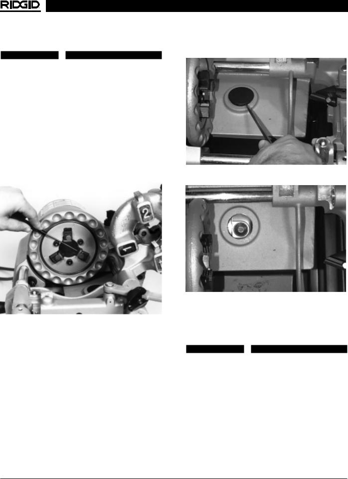
Jaw Replacement
1.To remove insert — place punch into spring detente slot of jaw and push down. (Figure 19)
2.Continue to push down on spring detente and slowly slide jaw out of chuck jaw holder. Remove insert.
3.Install new insert — place into chuck jaw holder and with finger depress spring and plunger. Slowly move insert past spring and plunger until insert fully sits in chuck jaw holder.
Figure 19 – Replacing Jaw Inserts
Replacing Carbon Brushes
NOTE! Check motor brushes every 6 months and replace when worn to less than 1/2″ .
1.Unplug machine from power source.
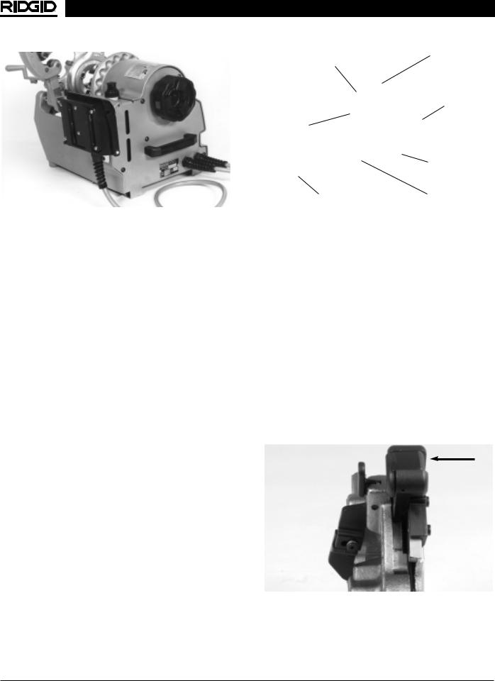
2.Using a screwdriver, remove the brush cap plug from the machine housing (Figure 20) exposing the first brush cap (Figure 21).
3.Remove the bottom cover screws and bottom cover, exposing the second brush cap.
4.Remove the brush caps.
5.Carefully remove the carbon brushes.
6.Install new carbon brushes.
7.Reinstall the brush caps, brush cap plug, and the bottom cover.
Figure 20 – Removing Brush Cap Plug
Figure 21 – Brush Cap Plug Removed, Brush Holder
Exposed
Machine Storage
 WARNING
Motor-driven equipment must be kept indoors or well covered in rainy weather. Store the machine in a locked area that is out of reach of children and people unfamiliar with power drives. This machine can cause serious injury in the hands of untrained users.
Ridge Tool Company |
13 |

1210 Oil-less Threading Machine
Service and Repair
 WARNING
The “Maintenance Instructions” will take care of most of the service needs of this tool. Any problems not addressed by this section should only be handled by an authorized RIDGID service technician.
Tool should be taken to a RIDGID Independent Authorized Service Center or returned to the factory. All repairs made by Ridge service facilities are warranted against defects in material and workmanship.
 WARNING
When servicing this machine, only identical replacement parts should be used. Failure to follow these steps may create a risk of electrical shock or other serious injury.
If you have any questions regarding the service or repair of this machine, call or write to:
Ridge Tool Company
Technical Service Department
400 Clark Street
Elyria, Ohio 44035-6001
Tel: (800) 519-3456
E-Mail: TechServices@ridgid.com
For name and address of your nearest Independent Authorized Service Center, contact the Ridge Tool Company at (800) 519-3456 or http://www.ridgid.com
14 |
Ridge Tool Company |

1210 Oil-less Threading Machine
Wiring Diagrams
120V 60 Hz
230V Europe
110V UK
100V Japan
230V Export
Ridge Tool Company |
15 |
 Loading...